| (19) |
 |
|
(11) |
EP 0 013 614 A1 |
| (12) |
EUROPEAN PATENT APPLICATION |
| (43) |
Date of publication: |
|
23.07.1980 Bulletin 1980/15 |
| (22) |
Date of filing: 07.01.1980 |
|
|
| (84) |
Designated Contracting States: |
|
AT BE CH DE FR IT LU NL SE |
| (30) |
Priority: |
09.01.1979 GB 7900806
|
| (71) |
Applicant: Bates, William Thomas Dennis |
|
Daventry, Northamptonshire (GB) |
|
| (72) |
Inventor: |
|
- Bates, William Thomas Dennis
Daventry, Northamptonshire (GB)
|
| (74) |
Representative: Hodding, Henry Squarey (GB) et al |
|
() |
|
| |
|
(57) A sample tube for obtaining a column of liquid of predetermined height in laboratory
applications comprises a simple and effective construction, with a local restriction
16 in internal diameter a predetermined distance from an inlet end 12 and a movable
valve member such as a lead shot 20 disposed in the tube between the restriction 16
and the opposite end 14, for co-operating with the restriction to retain a column
of liquid at the level of the valve member and restriction 16 by surface tension effects.
in operation, liquid is drawn into the tube by suction to a level substantially above
restriction 16, then the suction is removed and the liquid is allowed to drain out
of the end 12, passing the lead shot20 owing to an imperfect seal between the lead
shot and the restriction 16. When the liquid reaches the level of the lead shot and
restriction, it is retained at this level by surface tension effects interacting with
the lead shot and restriction.
|
|
[0001] This invention relates to a sample tube for obtaining a column of liquid of predetermined
length in laboratory applications, particularly when carrying out sedimentation tests.
[0002] It is known in laboratory testing to obtain a column of liquid by suction to the
upper end of a tube dipped at its lower end in the liquid sample. It is known for
a plug of fibrous material to be placed in the tube before sampling at the required
length from the lower end of the tube, the liquid being sucked into the tube to a
level above the plug and then allowed to flow out until the plug, by surface tension
effects, holds the liquid to the level of the plug. A particular test is then to allow
sediments in the liquid to settle in time and this test is applicable to blood analysis.
[0003] However, the insertion of plugs into tubes is difficult to automate and tends to
require a manual exercise.
[0004] This invention provides a sample tube having an inlet end for liquid to be sampled
and an opposite end for application of suction, the tube being formed with a restriction
locally in internal diameter a predetermined distance from the inlet end of the tube
and a movable valve member being disposed in the tube between the restriction and
said opposite end of the tube for co-operating with the restriction to retain a column
of liquid at the level of the valve member by surface tension effects. Preferably
the valve member is a spherical member, conveniently a lead shot, and the tube exhibits
a further local restriction between the first restriction and said opposite end of
the tube, or at said opposite end of the tube, to prevent the lead shot escaping.
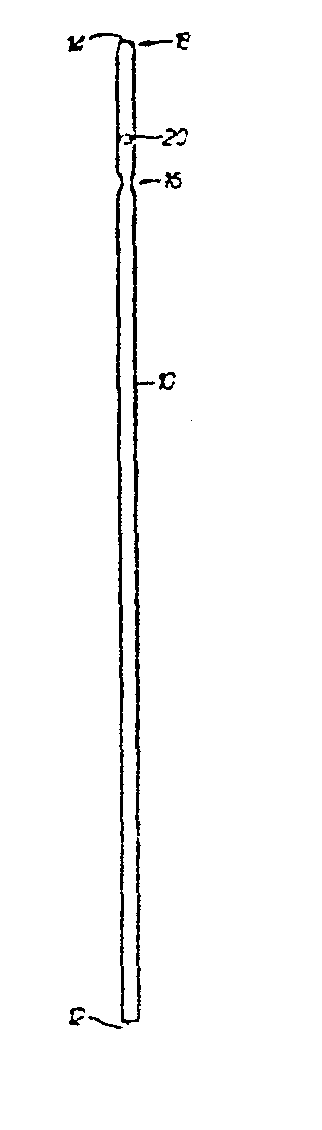
[0005] An embodiment of this invention will now be described, by way of example only, with
reference to the accompanying drawing, the single figure of which shows a sample tube
in accordance with the invention.
[0006] The sample tube shown comprises a straight glass tube 10 having opposite open ends
12,14 and having constant internal and external diameters along its length, except
at restrictions 16 and 18. A valve member 20, in the form of a lead shot, is disposed
in the tube between restrictions 16 and 18 and has a greater diameter than the internal
diameter of the tube at restrictions 16 and 18 so as to be retained between them.
However, the lead shot 20 has a smaller diameter than the internal diameter of the
unrestricted tube, so as to be free to move along the tube. The restriction 18 is
at the open end 14 of the tube but in general need.be at any position between restriction
16 and end 14 whilst enabling some longitudinal movement of the lead shot 20. The
restriction
16 is spaced from the end 12 of the tube by a distance equal to the required height
of the column of liquid and in the example shown is substantially closer to the end
14.
[0007] In use, the end 12 of the tube is dipped into the sample liquid to be tested and
suction is applied to the upper end 14 to draw the liquid into the tube. The lead
shot unseats readily from the restriction 16 to enable the liquid to be drawn in freely.
The suction is removed when the liquid level is above the restriction 16 and the lead
shot seats on this restriction under its own weight. Then the liquid is allowed to
drain, passing the lead shot owing to an imperfect sealing between the lead shot and
restriction 16, until the liquid level reaches the level of the lead shot and restriction
16. At this level, the liquid is retained by surface tension effects, interacting
with the lead shot and restriction
16.
[0008] The column of liquid thus obtained will be held indefinitely by these surface tension
effects. For a sedimentation test, as when testing blood, the manner and extent to
which settling occurs can then be monitored.
[0009] The sample tube which has been described is relatively simple to manufacture automatically
and is easy and effective in use.
1. A sample tube having an inlet end (12) for liquid to be sampled and an opposite
end (14) for application of suction to draw liquid into the tube when in generally
vertical position and provided with an arrangement within the tube, at a distance
from the inlet end of the tube, for retaining a column of liquid at the level of said
arrangement after the liquid has been drawn into the tube to substantially above said
arrangement and then allowed to drain down to that level, characterised in that the
column-retaining arrangement comprises a local restriction (16) in the internal diameter
of the tube and a movable valve member (20) disposed in the tube between the restriction
and said opposite end (14) of the tube and co-operating with the restriction to retain
the column of liquid at the level of the co-operating valve member and restriction.
2. A sample tube as claimed in claim 1, characterised in that the valve member is
arranged to seat on the restriction under its own weight before the liquid drains
down to said level, and such that the liquid drains between the valve member and restriction
after the valve . member seats on the restriction.
3. A sample tube as claimed in claim 1 or 2, characterised in that the valve member
is generally spherical in shape.
4. A sample tube as claimed in claim 3, characterised in that valve member comprises
a lead shot.
5. A sample tube as claimed in any preceding claim, characierised in that the tube
is provided with a second local restriction (18) in its internal diameter between
the first restriction and said opposite end of the tube, or at said opposite end of
the tube, to prevent the valve member escaping through said opposite end of the tube.
