| (19) |
 |
|
(11) |
EP 0 007 634 B1 |
| (12) |
EUROPEAN PATENT SPECIFICATION |
| (45) |
Mention of the grant of the patent: |
|
11.08.1982 Bulletin 1982/32 |
| (22) |
Date of filing: 26.07.1979 |
|
| (51) |
International Patent Classification (IPC)3: H01B 13/22 |
|
| (54) |
Apparatus and method for use in fluidized powder filling of multiple core unit cables
Vorrichtung und Verfahren zur Verwendung beim Auffüllen von Kabeln mit verschiedenen
Seelen-Einheiten mit Fliesspulver
Dispositif et méthode à utiliser pour le remplissage avec une poudre fluidisée de
câbles à plusieurs unités d'âmes
|
| (84) |
Designated Contracting States: |
|
BE CH DE FR GB NL SE |
| (30) |
Priority: |
31.07.1978 CA 308439
|
| (43) |
Date of publication of application: |
|
06.02.1980 Bulletin 1980/03 |
| (71) |
Applicant: NORTHERN TELECOM LIMITED |
|
Montreal
Quebec H3H 1R1 (CA) |
|
| (72) |
Inventor: |
|
- Garner, John Nicholas
Pointe Claire, Quebec, H9R 3H8 (CA)
|
| (74) |
Representative: Crawford, Andrew Birkby et al |
|
A.A. THORNTON & CO.
Northumberland House
303-306 High Holborn
London WC1V 7LE
London WC1V 7LE (GB) |
|
| |
|
| Note: Within nine months from the publication of the mention of the grant of the European
patent, any person may give notice to the European Patent Office of opposition to
the European patent
granted. Notice of opposition shall be filed in a written reasoned statement. It shall
not be deemed to
have been filed until the opposition fee has been paid. (Art. 99(1) European Patent
Convention).
|
[0001] This invention relates to apparatus and a method for fluidized powder filling of
multiple core unit cables.
[0002] Conventionally, a grease or jelly is used to fill the interstices between conductors
of a cable intended for use underground. Underground cables are provided with water
impermeable sheaths to prevent entry of moisture from the ground. Unfortunately, such
sheaths are sometimes damaged or cut into by contact with sharp objects such as rocks
and this then allows water to seep into the cables. The presence of water or moisture
within a cable has a deleterious affect upon the electrical properties of the conductors.
To prevent this from happening or to resist it, grease or jelly has been used to fill
the interstices between conductors thereby having the effect of preventing water access
between the conductors or to prevent the movement of water along the inside of the
cable after it has reached the conductors.
[0003] As grease or jelly is a messy and uncomfortable material to use and to work with
in finished cable, methods of filling the interstices with powder have been suggested
as an alternative, the powder also acting to prevent or restrict movement of moisture
or water along the conductors. Various methods of filling with powder have been suggested.
One of the most practical methods is to pass the cable core, with the conductors closed
together, through a fluidized bed of the powder. The closed together conductors pass
through the bed beneath its fluid surface and the minute gaps between outer conductors
are easily entered by the powder in its fluid condition whereby the powder passes
into the core and fills all of the interstices. This process is satisfactory for cores
below a certain size. However, for cores having a multiple unit construction, i.e.
core units each formed from a plurality of twisted together conductors with the units
themselves then twisted together, it is found that the fluidized powder does not enter
sufficiently far into the cable core to fill it.
[0004] On the other hand, it would be a simple matter to fill the interstices between conductors
of a single core unit, which may comprise up to fifty pairs of conductors. It has
been proposed therefore that to fill the interstices within multiple core unit construction,
the units should be passed through the fluidized bed in spaced-apart condition, so
that the interstices between conductors of each unit are filled, and then close the
units together to form the core while in the bed.
[0005] To powder fill a multiple core unit construction in the above way demands the use
of an opening device for opening the core into its separate units to enable the units
to move through the bed while spaced apart. It is known that to grease fill a cable
core, a pressurized chamber of grease is required and the core is passed through this.
Inside the chamber is a cable core opening device which is rotatable and separates
the conductors to the core to enable the grease to pass between them. One such arrangement
for grease filling in this manner is described in British Patent No. 1464747.
[0006] There is a problem, therefore, to provide an apparatus and method for separating
out the core units of a cable core and which may be used successfully together with
a fluidized powder filling bed while not being deleteriously affected by the presence
of the powder.
[0007] This problem is solved by the invention as set out in the appended claims to which
reference should now be made.
[0008] By the use of the method according to the invention, there is no drag on the rotational
movement of the core units as they pass in spaced relationship through the powder
bed. The fluidized powder filling operation and the allowing of the free rotational
movement of the opening member ensures the free passage of the core units in this
way. Such a method of powder filling would not be feasible with the use of ordinary
opening members having roller bearings and the freedom of movement of the core units
would not be possible.
[0009] The invention will be readily understood by the following description of certain
embodiments, by way of example, in conjunction with the accompanying drawings, in
which:-
Figure 1 is a diagrammatic longitudinal cross-section through a filling bed with an
opening device in the bed;
Figure 2 is a diagrammatic perspective view of the two basic parts of the device,
shown spaced apart for clarity;
Figure 3 is a cross-section on the line III-III of Figure 2, with the device as in
use;
Figure 4 is a diagrammatic longitudinal cross-section through a filling bed with an
opening device outside the bed, before entry of the cable core;
Figure 5 is a front view of the opening device in Figure 4, as it would be seen in
the direction of the arrow A in Figure 4;
Figure 6 is a cross-section on the line VI-VI of Figure 5, illustrating the opening
device in more detail;
Figure 7 is a perspective view on the inner face of the inlet wall of the bed, showing
an air collector;
Figure 8 is a cross-section through an alternative form of cable opening device, on
the line VIII-VIII of Figure 9;
Figure 9 is a face view in the direction of arrow A in Figure 8, with certain hidden
details shown in dotted outline.
Figure 10 is a partial cross-section, on the line X-X of Figure 8, illustrating the
structure at the periphery of the rotating member.
[0010] As illustrated in Figure 1, a fluidized powder filling bed is indicated generally
at 10, the powder being in the main portion 11 having a perforated base member 12,
an air box 13 under the member 12, with an air supply at 14. The main portion is covered
by a lid 15 and dust extraction is provided at 16. The bed can be supplied with powder
either by removing the lid or by providing an inlet. A typical form of bed is illustrated
in the above mentioned application.
[0011] A cable core 17 enters via an inlet die 18 and then the core is opened by the core
units passing through an opening device 19. After passage through the opening device
the core units close together, as indicated at 20, and then exit through an exit die
21. After passing through the exit die the core can be wrapped, for example by a tape
wrapping device 22 and tape 23. The opening device can be supported in the bed by
a support plate 24 extending across the main portion 11.
[0012] The opening device 19 is illustrated in more detail in Figures 2 and 3. The device
comprises a support member 25 attached to the support plate 24, and an opening member
26 which rides on the cable core 17, the core opens up into a plurality of core units
27. Support member 25 is annular in form and has an annular passage 28 formed from
the back surface. The back surface of the support member is held tight against the
support plate 22, as by screws at 29, and pressurized air is fed to the passage 28
via an inlet 30. Formed in the front face of the support member 25 are a number of
small orifices 31 communicating with the passage 28. In operation, with the opening
member 26 riding on the cable core, the drag on the opening member holds it against
the support member 25, and the opening member is also maintained in alignment with
the support member. High pressure air feeds through the orifices 31 and supports the
opening member 26 a short distance away from the support member, allowing virtually
friction free relative movement. The air also prevents fluidized powder penetrating
between the two members. Holes 32 are formed through the opening member 26 for passage
of core units therethrough.
[0013] To start the operation, the cable core is divided into the required number of core
units after passage through the inlet die 18. While seven are shown in Figures 2 and
3, a smaller number can occur, or a large number. For large cable cores more than
one row of holes 32 can be provided in the opening member. The individual core units
are then put through the holes 32, then through the centre of the support member 25
and then out through the exit die 21. Usually a pulling member is attached to the
end of the cable core to lead it through any successive stages and on to the take-up
spool. The bed is then closed, air admitted to the air box 13 and the powder fluidized.
The cable core is pulled through the bed, the core opening to pass through the opening
member 26 and then closing again. The powder fills the interstices between the conductors
in each core unit prior to the cable core closing together. There is some twist in
the core units, about the longitudinal axis of the core, and the opening member 26
can rotate relative to the support member 25 quite easily.
[0014] Figure 4 illustrates diagrammatically an alternative arrangement in which the opening
device 19 is mounted on the outside of the bed 10 at the inlet to the filling portion
11. Where applicable the same reference numerals are used in Figure 4, and in Figures
5 and 6, for the same items as in Figures 1 to 3. The cable core is opened into units
before entering the fluidized bed, closing again in the bed at 20.
[0015] Figures 5 and 6 illustrate in more detail the opening device 19 of Figure 4. In this
example a support member 40 is attached to the inlet end wall 41 of the main portion
11 of the bed. The support member 40 is tubular and has a conical support surface
42 and an annular wall 43 extending from the outer periphery of the conical surface
forming a chamber. An annular chanel 44 is formed in the back of the support member
and pressurized air is supplied to this channel via an inlet 45 connecting passage
46. Small orifices 47 extend from the support surface 42 through to the channel 44.
[0016] Positioned within the support member 40 is an opening member 50. The opening member
has a forward, conical surface 51 which is in opposition to surface 42. The periphery
of the opening member is afso a freely moveable fit inside the wall 43. An annular
chamber 52 is formed in the periphery of the opening member and pressurized air is
fed to this chamber via an inlet 53. From the chamber 52 air is fed via small diameter
bores 54 to holes 55 and 55a extending through the opening member and through which
pass the core units. The feature of the air supply bores 54 will be described later.
[0017] The rearward surface 56 of the opening member 50 is recessed around the periphery
to provide a rearward bearin surface 57, and a retaining member 58 is positioned in
the recess. The retaining member has a radially extending flange 59 which mates with
a radially extending flange 60 on the support member 40 and screws 61 connect the
two flanges together. A gasket 62 can be positioned between the flanges. The retaining
member has an annular cavity 63, closed by a cover plate 64 with a gasket 65. Small
orifices 66 connect the cavity 63 with the front surface 67 of the retaining member.
Pressurized air is fed to the cavity 63 via an inlet, not shown.
[0018] In operation, once the cable core has been initially opened and the core units passed
through the holes 55, and 55a through the bed 10, out through the unit die 21 and
on to the take up spool, air is supplied to the air box 13 to fluidize the powder
and also to the channel 44, chamber 52 and cavity 63.
[0019] The pressurized air fed to the channel 44 and cavity 63 flows through the orifices
47 and 66 and forms an air bearing between the support member and the opening member.
There is thus virtually no friction between support member and opening member. Air
will also flow between the outer periphery of the opening member and the inner surface
of the wall 43.
[0020] Although the core units are passing through the holes 55 and 55a at a fairly high
speed, say over 100 ft. per minute, powder tends to escape from the bed out through
the holes. By feeding air in via inlet 53, chamber 52 and bores 54, a small net flow
of air into the bed can be achieved, preventing outflow of powder. The flow of this
air can be controlled so that powder leakage is just prevented. The air flowing from
the orifice 47 between conical surfaces 42 and 51 flows out from between these surfaces
at the mounting position on the end wall 41. This flow could interfere with the fluidized
bed and a collection system can be provided. As seen in Figures 6 and 7, collector
member 68 is attached to the inside of the wall 41, the inner periphery of the member
68 situated in a recess 69 in the forward end of the opening member. The inner portion
of the member 68 is recessed on the side facing the support member 40 and opening
member 50 and forms an annular conduit 70 into which the air flows from between surfaces
42 and 51. The annular conduit 70 connects via passage 71 to an outlet 72 opening
into the space above the bed at 11. The bed exhaust is slightly below atmosphere pressure.
Similarly, an air supply can be provided to feed air to the holes 32 in the opening
member of Figures 1, 2 and 3.
[0021] Thus the opening member 50 rides freely on the cable core and can rotate freely within
the support member as the cable core passes through the bed. The number of holes 55
can very depending upon core size and number of core units. More than one row of holes
55 can be provided, as necessary. It is also possible to provide an opening member
with a large number of holes 55, with means for blocking those holes not used.
[0022] The arrangement illustrated in Figure 8 is for a large cable, the arrangement opening
the cable into 18 units. The arrangement comprises an opening member or rotor"80 having
eighteen axially extending holes 81 extending therethrough. The rotor is supported
in a support member or housing, indicated generally at 82, and has a central portion
83 of larger diameter than end portions 84 and 85. The housing 82 has a central portion
86 and end portions 87 and 88, the inner bores of the portions 86, 87 and 88 being
such that the rotor is a close rotating fit therein.
[0023] Inset into the central portion 86 of the housing 82 are a plurality of nozzle units
89 and a plurality of exhaust outlets 90. In the particular example illustrated there
are four nozzle units 89 spaced 90° apart round the central portion 86, and four exhaust
outlets 90 also spaced 90° apart and being midway between the nozzle units. Air is
supplied to the nozzle units 89 via pipes, not shown, connected to threaded inlets
91, and exhaust air is exhausted through pipes, not shown, connected to threaded outlets
99. The four nozzle units 89 and four exhaust outlets 90 are shown in dotted outline
in Figure 9.
[0024] Positioned in each nozzle unit 89 is a nozzle member 92, illustrated in cross-section
in Figure 10. The periphery of the central portion 83 of the rotor 80 has a plurality
of semicircular grooves 93 in alignment with the nozzle members 92. A circumferential
groove 94 extends on either side of the grooves 93. The grooves 93, with the nozzle
members 92, form an air turbine structure. Air admitted to a nozzle unit 89 is ejected
by the nozzle member to impinge on the grooves 93 to produce a rotational effort on
the rotor 80. The nozzle units 89 are mounted in circular housings 95 welded to the
housing 82. The nozzle units can be inserted in the housings in one of two directions,
either as illustrated in Figure 10, or rotated through 180°. Thus the nozzle member
can be positioned to eject air in one direction or another, 180° apart, and provides
for both rotational and braking effort as required.
[0025] The central portion 86 of the housing on either side of the central section is formed
by spacing members 96 to provide an annular air chamber 97. Small bores 98 extend
through the inner members 96, and air passes through the bores 98 to form an air bearing
between the periphery of the central portion of the rotor and the inner surfaces of
inner members 96.
[0026] Similarly end members 100 and 101 form annular air chambers 102 and 103, with small
bores 104 extending through the inner walls 105 of the chambers 102 and 103. Air flowing
through the bores 104 forms air bearings between the end surfaces 120 of the central
portion 83 of the rotor 80 and the end members 100 and 101.
[0027] Air, under pressure, is fed to chambers 102 and 103 via inlets 107 and 108 respectively
and to chambers 97 via one or more inlets 109. Air escaping by flowing down between
the end of the central portion 83 of the rotor and inner wall 105 of end member 100,
at the left side of Figure 8, can flow between the circumference of the reduced diameter
portion 84 and the end member into chamber 110 and exhaust via outlet 111.
[0028] Depending upon the size of cable, and the number of units the cable needs to be divided
into, so the rotor can have differing numbers of holes 81. For example rotors with
2 to 12 holes can be provided. Conveniently the dimensions of the rotor are standard,
apart from the number, and possibly diameter, of the holes 81. Rotors can be replaced
by removing the end portions 88 of the housing 82. The rotor 80 can then be slid out
and another replaced. The end portion 88 is located and held in place by dowels 112
and cam action studs 113.
[0029] In the example illustrated in Figures 8, 9 and 10, the cable moves through the rotor
in a direction indicated by the arrow X in Figure 8. The device is mounted on the
end wall of the inlet end of the fluidized bed housing, the wall indicated at 114
in Figure 8. Thus Figure 8 is in the opposite sense to the arrangement illustrated
in Figure 6. While the twist of the cable units themselves will tend to rotate the
rotor as the cable passes through the fluidized bed, with large cables the size of
the rotor can be such as to create significant rotational drag. The use of the "turbine"
effect of the nozzle members 92 and grooves 93 can be used to overcome this rotational
drag. However, under some circumstances, the rotor can tend to rotate faster than
is desired due to the rotation imposed on the motor by the cable. In such circumstances,
by reversing the inlet members, as described above, a braking effort can be applied
to the rotor. The "turbine" effect can be controlled by controlling the air supply
to the nozzle units 89. The number of nozzle units used can be varied, and the number
provided can also vary. The end loading imposed on the rotor, or opening member, 80
by passage of the cable is supported by the end member 100 which corresponds to the
support member 25 in Figures 2 and 3 and support member 40 in Figure 6. In the example
illustrated in Figure 8 the rotor or opening member 80 projects into a hole in the
end wall 114. However, the arrangement of Figures 8, 9 and 10 can be mounted on a
plate which in turn mounts on the end wall of the fluidized bed.
[0030] As a typical example, the bed 10 can be 1.22 metres long. The cable core units close
down at a position which can vary from about 15 cms to about 45 cms from the inlet
wall. The larger the cable the greater the distance the closing down from the inlet.
The bed can be made shorter, but the size given will accommodate various cable sizes.
It is believed that the length of the bed beyond the closing down of the core units
evens out the filling, but the majority of the filling occurs at the beginning before
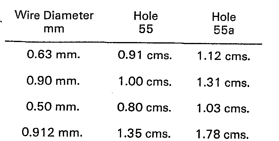
the core units close down. A typical air supply pressure is about 5.58 Kg/cm
2 although this can vary and lower pressures have been used. The air flows are quite
small. The size of the holes 32 and 55 will depend upon the size of the cable core
units passing therethrough. As an example, for the arrangement as illustrated in Figures
5 and 6, the tollowing table gives typical dimensions for a telecommunications cable,
in which the cable core has been divided up so that core units of alternatively twelve
and thirteen pairs pass through holes 55, and a twenty-five pair unit passes through
holes 55a. Other numbers of pairs per unit can be provided with corresponding adjustment
to the hole diameters.
[0031]
1. Apparatus for filling a multiple core unit cable core with filling material comprising:-
an opening device for opening a multiple core unit cable core into a plurality of
core units comprising:
a support member (25, 40, 82);
a rotatable opening member (19, 50, 80) positioned against the support member for
free rotation and defining a plurality of holes (22, 55, 55a, 81) extending in an
axial direction through the opening member in non alignment with the support member,
each hole adapted for passage of a core unit therethrough;
characterised by a surrounding structure (10) for containing a fluidisable bed of
filling powder (11) adapted for passage through the bed of a cable core; and
means (28, 30, 31, 44, 47, 102, 103, 104) for supplying pressurised air between the
opening member and the support member to form at least one air bearing therebetween.
2. Apparatus as claimed in claim 1, characterized by the opening member (19, 50, 80)
positioned adjacent to an end surface on the support member.
3. Apparatus as claimed in either of claims 1 and 2 characterized by means (52, 54)
for supplying pressurized air to the holes (55, 55a) extending through the opening
member at a position intermediate the ends of the holes.
4. Apparatus as claimed in any one of the preceding claims, characterized by the opening
member (19, 50) including a central hole (32", 55a) on the central axis of the opening member, and at least one circle of holes
(32, 55) around the central hole.
5. Apparatus as claimed in claim 4, characterized by each of the holes forming a circle
of holes being inclined inwardly towards the central axis, from an inlet surface to
an outlet surface on the opening member.
6. Apparatus as claimed in claim 4, characterized by hole (55a) being larger than
the holes forming a circle of holes.
7. Apparatus according to any preceding claim characterized in that the support member
(40, 82) has an annular wall (43, 86) and the opening member (50, 80) is disposed
within the annular wall and the plurality of holes are disposed radially within the
support member.
8. Apparatus according to claim 7, characterized in that the support member has an
end wall (42) defining a conical support surface at one axial end of the annular wall
(43) and the opening member (50) includes a conical surface (51) in cooperative opposition
to the conical support surface.
9. Apparatus according to claim 8, characterized in that the end wall has an outer
surface formed with an annular channel (44) and orifices (47) are provided in the
end wall from the channel to the conical support surface to supply pressurized air
from the channel between the support member and the opening member.
10. Apparatus according to claim 7, characterized in that the opening member (50)
includes a cylindrical portion freely rotatable within the annular wall, an annular
chamber (52) formed in the outer periphery of the cylindrical portion, means (53)
for feeding pressurized air through the annular wall to the annular chamber (52),
and bores (54) extending from the annular chamber (52) to the holes (55, 55a) extending
through the opening member (50) for supplying pressurized air to the holes (55, 55a).
11. Apparatus according to claim 7, characterized in that there is provided an annular
retaining member (58) attached to an outer wall of the annular wall (43) and extending
radially inward thereof; a front surface on the retaining member; a rearward bearing
surface on the opening member (50) in opposition to the front surface on the retaining
member; an annular cavity (63) in the retaining member; means for feeding pressurized
air to the annular cavity and orifices (66) extending from the cavity to the front
surface of the retaining member to feed pressurized air between the front surface
and the rearward bearing surface for formation of an air bearing therebetween.
12. Apparatus according to claim 1, characterized by the support member (82) comprising
a tubular housing having a cylindrical central portion (86) and cylindrical end portions
(87, 88), on either side of the central portion, the end portions having an internal
diameter smaller than the internal diameter of the central portion, one of the end
portions forming an end surface, the opening member (80) comprising a rotor rotatably
mounted in the housing and having a centre portion (83) and end portions (84, 85)
on either side of the centre portion, the diameters of the end portions and centre
portion of the rotor being a close rotating fit in the end portions and central portion
respectively of the housing; axially extending grooves (93) in the periphery of the
central portion of the rotor and at least one nozzle member (92) in the central portion
of the housing, and air supply means (91) to the nozzle member, whereby pressurized
air ejecting from the nozzle member acts on the grooves to provide a rotational force
on the rotor; the end portions of the housing including surfaces in opposition to
end walls on the central portion of the rotor, and means (102, 103, 104), for supplying
pressurized air between the end walls and the surfaces; and means (97, 98) for supplying
pressurized air between the periphery of the central portion of the rotor and the
inner surface of the central portion of the housing to form at least one air bearing
therebetween.
13. Apparatus as claimed in claim 12, characterized by the axially extending grooves
(93) being of hemispherical cross-section, the nozzle member having an outlet inclined
relative to the axes of the grooves.
14. Apparatus as claimed in either of claim 12 or 13, characterized by each nozzle
member (92) being mounted in a nozzle unit (89), and including means for attaching
the nozzle unit to the housing to permit attachment of the nozzle unit in either of
two positions, of 180° rotation apart.
15. Apparatus as claimed in claim 4, characterized by the opening member (80) including
a plurality of circles of holes (81) around the central hole, the axes of all of the
holes parallel to each other.
16. Apparatus according to claim 1, characterized by the support member (25, 40) and
the opening member (19, 50, 80) are mounted at an inlet end (41) of the structure
(10), and a hole extends through the structure in alignment with the opening member.
17. Apparatus according to claim 1, characterized by the support member (25) and the
opening member (19) mounted within the structure for immersion within the bed.
18. Apparatus according to claim 16, characterized by an air collector member (68)
mounted upon the inner side of the inlet end (41) for collection of air flowing from
between the support member (40) and the opening member (50) and an outlet (72) connected
to the collector member.
19. Apparatus according to claim 18, characterized by the outlet (72) connected to
an air space above the fluidized bed at a pressure slightly below atmospheric pressure.
20. A method of filling a multiple core unit cable core with filling material with
each unit comprising a multiplicity of conductors by opening the cable core (17) to
space-apart the multiple core units (27) by passing the core units divergently towards
and through a plurality of axially extending and spaced-apart holes (22, 55, 55a,
81) defined in a core cpening member (19, 50, 80), minimizing rotational drag on the
core units as they pass through the holes, feeding the spaced core units, each with
its conductors closed together, through a filling chamber to fill the interstices
between conductors of each unit, and causing the core units to close together within
the filling chamber after passing through the hole so as to reclose the cable core,
the twist of the core units in the core causing the opening member to rotate with
substantially no frictional resistance to rotation, characterized by filling the interstices
with powder in a fluidized powder bed (11), the powder in the bed flowing into the
interstices between conductors of each unit, and applying pressurized air between
the opening member and a support member (25, 40, 82) to form an air bearing therebetween
and allow for free rotation of the opening member.
21. A method according to claim 20, characterized by pressuring the spaced-apart holes
with air during passage of the core units to prevent entry of powder into the holes.
1. Vorrichtung zum Füllen einer eine Vielzahl Adereinheiten umfassenden Kabelseele
mit einem Füllmaterial, mit einer Öffnungseinrichtung zum Öffnen einer von einer mehradrigen
Einheit gebildeten Kabelseele in eine Vielzahl von Adereinheiten, die ein Stützelement
(25, 40, 82) und ein drehbares Öffnungselement (19, 50, 80) umfaßt, welches zur freien
Drehnung gegen das Stützelement positioniert ist und eine Vielzahl von Öffnungen (22,
55, 55a, 81) festlegt, welche sich in axialer Richtung durch aus Öffnungselement in
Nichtausrichtung zu dem Stützelement erstrecken, wobei jede Öffnung zum Durchführen
einer Adereinheit geeignet ist, gekennzeichnet durch eine umgebende Struktur (10)
zum Aufnehmen eines fluidisierbaren Bettes aus Füllpulver (11), wobei die Struktur
zum Durchführen einer Kabelseele durch das Bett hindurch geeignet ist, und durch eine
Einrichtung (28, 30, 31, 44, 47, 102, 103, 104) zum Zuführen von Druckluft zwischen
das Öffnungselement und das Stützelement, um dazwischen wenigstens ein Luftlager zu
bilden.
2. Vorrichtung nach Anspruch 1, dadurch gekennzeichnet, daß das Öffnungselement (19,
50, 80) anschließend an eine Endfläche an dem Stützelement positioniert ist.
3. Vorrichtung nach Anspruch 1 oder 2, gekennzeichnet durch eine Einrichtung (52,
54) zum Zuführen von Druckluft zu den Öffnungen (55, 55a), die sich durch das Öffnungselement
an einer Stelle zwischen den Enden der Öffnungen erstreckt.
4. Vorrichtung nach irgendeinem der vorhergehenden Ansprüche, dadurch gekennzeichnet,
daß das Öffnungselement (19, 50) eine mittige Öffnung (32, 55a) auf der Mittelachse
des Öffnungselementes und wenigstens einen Kreis von Öffnungen (32, 55) um die mittlere
Öffnung herum aufweist.
5. Vorrichtung nach Anspruch 4, dadurch gekennzeichnet, daß jede der einen Kreis von
Öffnungen bildenden Öffnungen nach innen in Richtung auf die Mittelachse von einer
Einlaßoberfläche zu einer Auslaßoberfläche des Öffnungselementes schräg verläuft.
6. Vorrichtung nach Anspruch 4, dadurch gekennzeichnet, daß die Öffnung (55a) größer
als die einen Kreis von Öffnungen bildenden Öffnungen ist.
7. Vorrichtung nach irgendeinem der vorhergehenden Ansprüche, dadurch gekennzeichnet,
daß das Stützelement (40, 82) eine Ringwand (43, 86) aufweist und daß das Öffnungselement
(50, 80) innerhalb der Ringwand angeordnet ist und die Vielzahl von Öffnungen radial
innerhalb des Stützelementes angeordnet sind.
8. Vorrichtung nach Anspruch 7, dadurch gekennzeichnet, daß das Stützelement eine
Endwand (42) aufweist, welche eine konische Stützfläche an einem axialen Ende der
Ringwand (43) festlegt, und daß das Öffnungselement (50) eine konische Oberfläche
(51) in zusammenarbeitender Gegenüberlage zu der konischen Stützfläche aufweist.
9. Vorrichtung nach Anspruch 8, dadurch gekennzeichnet, daß die Endwand eine mit einem
Ringkanal (44) ausgebildete Außenfläche aufweist und daß Öffnungen (47) in der Endwand
von dem Kanal zu der konischen Stützfläche vorgesehen sind, um Druckluft von dem Kanal
zwischen das Stützelement und das Öffnungselement zuzuführen.
10. Vorrichtung nach Anspruch 7, dadurch gekennzeichnet, daß das Öffnungselement (50)
einen zylinderförmigen, innerhalb der Ringwand frei drehbaren Abschnitt, eine in der
äußeren Umfangsfläche des zylinderförmigen Abschnittes ausgebildete, ringförmige Kammer
(52), eine Einrichtung (53) zum Zuführen von Druckluft durch die Ringwand zu der ringförmigen
Kammer (52) und Bohrungen (54) aufweist, die sich von der ringförmigen Kammer (52)
zu den sich durch das Öffnungselement (50) erstreckenden Öffnungen (55, 55a) erstrecken,
um Druckluft den Öffnungen (55, 55a) zuzuführen.
11. Vorrichtung nach Anspruch 7, dadurch gekennzeichnet, daß vorgesehen sind ein ringförmiges
Halteelement (58), welches an einer Außenwand der Ringwand (43) befestigt ist und
sich von dieser radial nach innen erstreckt, eine Vorderfläche an dem Halteelement,
eine hintere Lagerfläche an dem Öffnungselement (50) in 'Gegenüberlage zu der Vorderfläche
an dem Halteelement, ein ringförmiger Hohlraum (63) in dem Halteelement und eine Einrichtung
zum Zuführen von Druckluft zu dem ringförmigen Hohlraum und den Öffnungen (66), die
sich von dem Hohlraum zur Vorderfläche des Halteelementes erstrecken, um Druckluft
zwischen die Vorderfläche und die hintere Lagerfläche zur Ausbildung eines Luftlagers
dazwischen zuzuführen.
12. Vorrichtung nach Anspruch 1, dadurch gekennzeichnet, daß das Stützelement (82)
ein rohrförmiges Gehäuse mit einem zylinderförmigen, mittleren Abschnitt (86) und
zylinderförmigen Endabschnitten (87, 88) an beiden Seiten des mittleren Abschnittes
aufweist, wobei die Endabschnitte einen kleineren Innendurchmesser als der Innendurchmesser
des mittleren Abschnittes haben und einer der Endabschnitte eine Endfläche bildet,
daß das Öffnungselement (80) einen Rotor umfaßt, der drehbar in dem Gehäuse angeordnet
ist und einen mittleren Abschnitt (83) und auf beiden Seiten des mittleren Abschnittes
Endabschnitte (84, 85) aufweist, wobei die Durchmesser der Endabschnitte und des mittleren
Abschnittes des Rotors eine dichte Drehpassung in den Endabschnitten bzw. in dem mittleren
Abschnitt des Gehäuses aufweisen, daß sich axial erstreckende Nuten (93) in dem Umfang
des mittleren Abschnittes des Rotors und wenigstens ein Düsenelement (92) in dem mittleren
Abschnitt des Gehäuses und eine Luftzuführeinrichtung (91) zu dem Düsenelement vorgesehen
sind, wobei von dem Düsenelement austretende Druckluft an den Nuten wirkt, um eine
Drehkraft an dem Rotor hervorzurufen, daß die Endabschnitte des Gehäuses Oberflächen
in Gegenüberlage zu den Endwänden an dem mittleren Abschnitt des Rotors und Mittel
(102, 103, 104) zum Zuführen von Druckluft zwischen die Endwände und die Oberflächen
aufweisen, und daß Mittel (97, 98) zum Zuführen von Druckluft zwischen den Umfang
des mittleren Abschnittes des Rotors und die innere Oberfläche des mittleren Abschnittes
des Gehäuses vorgesehen sind, um dazwischen wenigstens ein Luftlager zu bilden.
13. Vorrichtung nach Anspruch 12, dadurch gekennzeichnet, daß die sich axial erstreckenden
Nuten (93) einen halbkugelförmigen Querschnitt aufweisen und daß das Düsenelement
einen relativ zu den Achsen der Nuten schräg verlaufenden Auslaß aufweist.
14. Vorrichtung nach Anspruch 12 oder 13, dadurch gekennzeichnet, daß jedes Düsenelement
(92) in einer Düseneinheit (89) befestigt ist und daß Mittel zur Befestigung der Düseneinheit
an dem Gehäuse vorgesehen sind, um die Befestigung der Düseneinheit in einer beliebigen
von zwei Positionen zu ermöglichen, die un eine Drehnung von 180° voneinander entfernt
sind.
15. Vorrichtung nach Anspruch 4, dadurch gekennzeichnet, daß das Öffnungselement (80)
eine Vielzahl von Kreisen von Öffnungen (81) um die mittlere Öffnung herum aufweist,
wobei die Achsen aller dieser Öffnungen parallel zueinander verlaufen.
16. Vorrichtung nach Anspruch 1, dadurch gekennzeichnet, daß das Stützelement (25,
40) und das Öffnungselement (19, 50, 80) an einem Eintrittsende (41) der Stuktur (10)
angeordnet sind, und daß sich eine Öffnung durch die Struktur in Ausrichtung zu dem
Öffnungselement erstreckt.
17. Vorrichtung nach Anspruch 1, dadurch gekennzeichnet, daß das Stützelement (25)
und. das Offnungselement (19) innerhalb der Struktur zum Eintauchen in das Bett angeordnet
sind.
18. Vorrichtung nach Anspruch 16, dadurch gekennzeichnet, daß ein Luftsammelelement
(68) auf der Innenseite des Einlaßendes (41) befestigt ist, um Luft zu sammeln, welche
von zwischen dem Stützelement (40) und dem Öffnungselement (50) und einem Auslaß (72),
welcher mit dem Sammelelement verbunden ist, herströmt.
19. Vorrichtung nach Anspruch 18, dadurch gekennzeichnet, daß der Auslaß (72) mit
einem Luftraum oberhalb des fluidisierten Bettes auf einem etwas unterhalb des Atmosphärendruckes
liegenden Druckes verbunden ist.
20. Verfahren zum Füllen einer eine Vielzahl von Adereinheiten, die jeweils eine Vielzahl
von Leitern aufweist, umfassenden Kabelseele mit einem Füllmaterial, bei dem die Kabelseele
(17) zur Beabstandung der Vielzahl von Adereinheiten (17) voneinander geöffnet wird,
indem die Adereinheiten divergierend in Richtung auf und durch eine Vielzahl von sich
axial erstreckenden und voneinander beabstandeten, in einem Kabelseele-Öffnunqselement
(19, 50, 80) festgelegte Öffnungen geführt werden, bei dem der Drehzugwiderstand an
den Adereinheiten minimalisiert wird, wenn sie durch die Öffnungen hindurch gehen,
bei dem die beabstandeten Adereinheiten mit jeweils miteinander zusammengeschlossenen
Leitern durch eine Füllkammer gefördert werden, um die Zwischenräume zwischen den
Leitern einer jeden Einheit zu füllen, und bei dem bewirkt wird, daß die Adereinheiten
innerhalb der Füllkammer nach dem Hindurchgehen durch die Öffnungen zusammengeschlossen
werden, um damit die Kabelseele erneut zu schließen, wobei der Drall der Adereinheiten
in der Seele bewirkt, daß sich das Öffnungselement mit im wesentlichen ohne Reibungswiderstand
gegenüber einer Drehung dreht, dadurch gekennzeichnet, daß die Zwischenräume in einem
fluidisierten Pulverbett (11) gefüllt werden, wobei das Pulver in dem Bett in die
Zwischenräume zwischen den Leitern einer jeden Einheit fließt, und daß Druckluft zwischen
das Öffnungselement und ein Stützelement (25, 40, 82) eingebracht wird, um dazwischen
ein Luftlager zu bilden und eine freie Drehung des Öffnungselementes zu ermöglichen.
21. Verfahren nach Anspruch 20, dadurch gekennzeichnet, daß den voneinander beabstandeten
Öffnungen Druckluft während des Durchganges der Adereinheiten zugeführt wird, um den
Eintritt von Pulver in die Öffnungen zu verhindern.
1. Appareil de remplissage de l'âme d'un câble à âme à plusieurs éléments à l'aide
d'une matière de remplissage, comprenant:
- un dispositif d'écartement de l'âme d'un câble en plusieurs éléments d'âme, comprenant:
- un organe de support (25, 40, 82),
- un organe rotatif d'écartement (19, 50, 80) placé contre l'organe de support afin
qu'il tourne librement et délimitant plusieurs trous (22, 55, 55a, 81) disposés en
direction axiale dans l'organe d'écartement à des emplacements non alignés sur l'organe
de support, chaque trou étant destiné au passage d'un élément d'âme,
- caractérisé par une structure (10) destinée à contenir un lit fluidisable d'une
poudre de remplissage (11) et destinée à permettre le passage dans le lit d'une âme
de câble autour de laquelle elle est placée, et
- un dispositif (28, 30, 31, 44, 47, 102, 103, 104) destiné à transmettre de l'air
comprimé entre l'organe d'écartement et l'organe de support afin qu'ils forment au
moins un palier pneumatique entre eux.
2. Appareil selon la revendication 1, caractérisé en ce que l'organe d'écartement
(19, 50, 80) est placé près d'une face d'extrémité sur l'organe de support.
3. Appareil selon l'une des revendications 1 et 2, caractérisé en ce qu'il comprend
un dispositif (52, 54) destiné à transmettre de l'air comprimé aux trous (55, 55a)
traversant l'organe d'écartement dans une position comprise entre les extrémités des
trous.
4. Appareil selon l'une quelconque des revendications précédentes, caractérisé en
ce que l'organe d'écartement (19, 50) a un trou central (32, 55a) placé sur l'axe
central de l'organe d'écartement et au moins un cercle de trous (32, 55) disposé autour
du trou central.
5. Appareil selon la revendication 4, caractérisé en ce que chacun des trous du cercle
de trous est incliné vers l'intérieur, vers l'axe central, depuis une surface d'entrée
vers une surface de sortie formée sur l'organe d'écartement.
6. Appareil selon la revendication 4, caractérisé en ce que le trou (55a) est plus
gros que les trous formant un cercle de trous.
7. Appareil selon l'une quelconque des revendications précédentes, caractérisé en
ce que l'organe de support (40, 82) a une paroi annulaire (43, 86) et l'organe d'écartement
(50, 80) est disposé à l'intérieur de la paroi annulaire et les trous sont disposés
radialement à l'intérieur de l'organe de support.
8. Appareil selon la revendication 7, caractérisé en ce que l'organe de support a
une paroi d'extrémité (42) délimitant une surface conique de support à une première
extrémité axiale de la paroi annulaire (43) et l'organe d'écartement (50) a une surface
conique (51) disposée en face de la surface conique de support avec laquelle elle
est destinée à coopérer.
9. Appareil selon la revendication 8, caractérisé en ce que la paroi d'extrémité a
une surface externe ayant un canal annulaire (44) et des orifices (47) sont formés
dans la paroi d'extrémité à partir du canal vers la surface conique de support afin
que de l'air comprimé soit transmis à partir du canal entre l'organe de support et
l'organe d'écartement.
10. Appareil selon la revendication 7, caractérisé en ce que l'organe d'écartement
(50) a une partie cylindrique qui peut tourner librement à l'intérieur de la paroi
annulaire, une chambre annulaire (52) formée dans la périphérie externe de la partie
cylindrique, un dispositif (53) d'alimentation d'air comprimé à travers la paroi annulaire
vers la chambre annulaire (52), et des alésages (34) allant de la chambre annulaire
(52) aux trous (55, 55a) et traversant l'organe d'écartement (50) afin qu'ils transmettent
l'air comprimé aux trous (55, 55a).
11. Appareil selon la revendication 7, caractérisé en ce qu'il comporte un organe
annulaire de retenue (58) fixé à une paroi externe de la paroi annulaire (43) et disposé
radialement vers l'intérieur par rapport à celle-ci. une face avant formée sur l'organe
de retenue, une surface arrière de paiier formée sur l'organe d'écartement (50) en
face de la surface avant formée sur l'organe de retenue, une cavité annulaire (63)
formée dans l'organe de retenue, un dispositif d'alimentation d'aire comprimé dans
la cavité annulaire et des orifices (66) partant de la cavité et rejoignant la face
avant de l'organe de retenue afin que l'air comprimé soit transmis entre la face avant
et la face arrière de palier et qu'un palier pneumatique soit formé entre elles.
12. Appareil selon la revendication 1, caractérisé en ce que l'organe de support (82)
comporte un boîtier tubulaire ayant une partie centrale cylindrique (86) et des parties
cylindriques d'extrémités (87, 88), de part et d'autre de la partie centrale, les
parties d'extrémités ayant un diamètre interne inférieur à celui de la partie centrale,
une première partie d'extrémité formant une surface d'extrémité, l'organe d'écartement
(80) comportant un rotor monté dans le boîtier afin qu'il tourne et ayant une partie
centrale (83) et des parties d'extrémités (84, 85) de part et d'autre de la partie
centrale, les diamètres des parties d'extrémités et de la partie centrale du rotor
étant ajustés dans les parties d'extrémités et la partie centrale respectivement du
boîtier tout en pouvant tourner, des gorges axiales (93) formées à la périphérie de
la partie centrale du rotor et au moins une buse (92) placée dans la partie centrale
du boîtier, et un dispositif d'alimentation en air (91) de la buse, tel que de l'air
comprimé projeté par la buse agit sur les gorges en appliquant une force de rotation
au rotor, les parties d'extrémités du boîtier ayant - des surfaces placées en regard
des parois d'extrémités sur la partie centrale du rotor, et un dispositif (102, 103,
104) destiné à transmettre de l'air compnmé entre les parois d'extrémités et les surfaces,
et un dispositif (97, 98) destiné à transmettre de l'air comprimé entre la périphérie
de la partie centrale du rotor et la face interne de la partie centrale du boîtier
afin qu'au moins un palier pneumatique soit formé entre elles.
13. Appareil selon la revendication 12, caractérisé en ce que les gorges axiales (93)
ont une section hémisphérique, la buse ayant une sortie inclinée par rapport aux axes
des gorges.
14. Appareil selon l'une des revendications 12 et 13, caractérisé en ce que chaque
buse (92) est montée dans un ensemble (89), et l'appareil comprend un dispositif destiné
à fixer l'ensemble à buse sur le boîtier afin que cel ensemble puisse être fixé dans
l'une de deux positions séparées de 1800.
15. Appareil selon la revendication 4, caractérisé en ce que l'organe d'écartement
(80) a plusieurs cercles de trous (81) placés autour du trou central, les axes de
tous les trous étant parallèles les uns aux autres.
16. Appareil selon la revendication 1, caractérisé en ce que l'organe de support (25,
40) et l'organe d'écartement (19, 50, 80) sont montés à une extrémité d'entrée (41)
de la structure (10), et un trou traverse la structure dans l'alignement de l'organe
d'écartement.
17. Appareil selon la revendication 1, caractérisé en ce que l'organe de support (25)
et l'organe d'écartement (19) sont montés à l'intérieur de la structure afin qu'ils
soient immergés dans le lit.
18. Appareil selon la revendication 16, caractérisé en ce qu'un organe collecteur
d'air (68) est monté sur la face interne de l'extrémité d'entrée (41) afin qu'il rassemble
l'air provenant de l'espace compris entre l'organe de support (40) et l'organe d'écartement
(50), et une sortie (72) est reliée à l'organe collecteur.
19. Appareil selon la revendication 18, caractérisé en ce que la sortie (72) est reliée
à un espace contenant de l'air, formé au-dessus du lit fluidisé et ayant une pression
légèrement inférieure à la pression atmosphérique.
20. Procédé de remplissage d'une âme de câble à plusieurs éléments d'âme à l'aide
d'une matière de remplissage, chaque élément comprenant plusieurs conducteurs, par
écartement de l'âme du câble (17) afin que les éléments d'âme (27) soient espacés
par passage d'une manière divergente vers des trous axiaux et espacés (22, 55, 55a,
81) formés dans un organe d'écartement d'âme (19, 50, 80) et dans ces trous, la réduction
au minimum de la force de frottement par rotation des éléments d'âme lorsqu'ils passent
dans les trous, l'avance des éléments distants d'âme, ayant chacun ses conducteurs
rapprochés, dans une chambre de remplissage afin que les interstices délimités entre
les conducteurs de chaque élément soient remplis, et le rapprochement des éléments
d'âme à l'intérieur de la chambre de remplissage après passage dans les trous afin
que l'âme du câble soit resserrée, la torsion des éléments compris dans l'âme provoquant
la rotation de l'organe d'écartement avec une résistance de frottement pratiquement
nulle en rotation, caractérisé par le remplissage des interstices avec une poudre
placée dans un lit fluidisé (11) de poudre, la poudre du lit s'écoulant par pénétration
dans les interstices des conducteurs de chaque élément, et par transmission d'air
comprimé entre l'organe d'écartement et un organe de support (22, 40, 82) afin qu'un
palier pneumatique soit formé entre eux et permette une rotation libre de l'organe
d'écartement.
21. Procédé selon la revendication 21, caractérisé en ce qu'il comprend la mise sous
pression des trous distants avec de l'air lors du passage des éléments d'âme afin
que la poudre ne puisse pas pénétrer dans les trous.