| (19) |
 |
|
(11) |
EP 0 012 780 B1 |
| (12) |
EUROPEAN PATENT SPECIFICATION |
| (45) |
Mention of the grant of the patent: |
|
25.05.1983 Bulletin 1983/21 |
| (22) |
Date of filing: 20.11.1978 |
|
|
| (54) |
Tractor front implement hitch
Kupplungsvorrichtung an der Vorderseite eines Ackerschleppers
Attelage frontal pour tracteur
|
| (84) |
Designated Contracting States: |
|
BE DE FR GB NL SE |
| (30) |
Priority: |
21.11.1977 US 853783
|
| (43) |
Date of publication of application: |
|
09.07.1980 Bulletin 1980/14 |
| (71) |
Applicant: MASSEY-FERGUSON SERVICES N.V. |
|
Curaçao (AN) |
|
| (72) |
Inventor: |
|
- Old, John Leslie
Kenilworth
Warwickshire (GB)
|
| (74) |
Representative: Jones, David Bryn |
|
Eaton Lodge
Coventry Road
GB-Kenilworth, Warwicks. CV8 2FU
GB-Kenilworth, Warwicks. CV8 2FU (GB) |
|
| |
|
| Note: Within nine months from the publication of the mention of the grant of the European
patent, any person may give notice to the European Patent Office of opposition to
the European patent
granted. Notice of opposition shall be filed in a written reasoned statement. It shall
not be deemed to
have been filed until the opposition fee has been paid. (Art. 99(1) European Patent
Convention).
|
Technical Field
[0001] The present invention relates generally to an implement hitch, and more particularly
to an implement hitch for securing an implement forwardly of a propelling tractor.
Background Art
[0002] While implement hitches have been known for a considerable number of years, these
hitches have been customarily mounted on the rear of a tractor and the implement secured
to the tractor in trailing relationship.
[0003] More recently implements have been secured to the front of a tractor by hitches.
An example of such a front hitch is shown in AT-B-322886.
[0004] As will be appreciated by those having ordinary skill in the art, a hitch will function
in a manner somewhat differently when applied to the front of a tractor than when
applied to the rear of a tractor. Thus, the lower links will be in compression and
it will be necessary to maintain the implement substantially directly in front of
the tractor. This has been accomplished by stabilizing the lower links. The links
may be stabilized in such a manner that some side to side sway or horizontal float
is permitted within set limits. Alternatively, all side to side sway may be eliminated.
This will depend upon the type of implement supported by the hitch. As a general rule,
those implements which engage the ground are permitted to sway within set limits while
those implements which do not engage the ground are not permitted to sway.
[0005] One manner in which the lower links of front mounted hitches have been stabilized
in the past has been to extend a strut from the rear end of one lower link to the
forward end of the other lower link. Alternatively, stabilizer chains have been employed.
While such devices have performed their intended function in a generally satisfactory
manner, it is necessary to provide these devices with adjustment provisions to accommodate
the different types of implements referred to in the preceding paragraph. In addition,
as the distance between the hitch pins varies from one category of implement to another
category of implement, large variations in the length of the struts and stabilizer
chains must be provided for in order to accommodate the varying implements. It should
be appreciated that such adjustments in length of stabilizer chains and strut may
not be easily accomplished. In addition, it may be necessary to disconnect such devices
when mounting or removing an implement from the hitch. Furthermore, such devices may
interfere with any tractor power takeoff shaft employed to drive an implement mounted
on the front hitch.
Disclosure of Invention
[0006] It is one object of the present invention to provide a front implement hitch having
improved means for stabilizing its lower links thus overcoming the disadvantages of
the prior art stabilizing means discussed above.
[0007] According to one aspect of the present invention there is provided a front hitch
for mounting, the hitch including, a pair of laterally spaced apart lower links arranged
to extend forwardly of the tractor when in use, the forward ends of the lower links
being provided with attachment means for the implement and being movable vertically
and swingable from side to side, and a pair of laterally spaced apart mounting means
associated with the tractor for mounting the rear ends of the lower links, said hitch
being characterized in that at least one of the mounting means includes adjustment
means for adjusting the lateral spacing between the rear ends of the lower links,
and in that a pair of vertical rubbing surfaces are provided on the hitch for abutment
with an intermediate portion of the lower links to limit the side to side sway of
the lower links.
[0008] It will be appreciated that by adjusting the lateral spacing between the rear ends
of the lower links the amount of sway which the rubbing surfaces permit can be easily
adjusted and sway can be eliminated if desired by making this lateral spacing sufficiently
small. The hitch construction described in the preceding paragraph thus includes an
improved means for stabilising the lower links which overcomes the disadvantages described
above. The above adjustment feature also enables implements of different categories
to be accommodated by the hitch.
[0009] In a preferred construction at least one of the lower links includes an apertured
mounting ball at the rear end and the associated adjustment means includes a laterally
shiftable pin which receives the mounting ball.
[0010] Preferably the adjustment means includes a rotatable threaded member parallel to
the laterally shiftable pin, said threaded member passing through a threaded aperture
within the support frame with an interconnecting member interconnecting said pin with
the threaded member to affect movement of said pin when said threaded member is rotated
relative to the threaded aperture.
[0011] Preferably each mounting means includes adjustment means so that each of the lower
links can be independently adjusted.
[0012] This invention also provides a front implement hitch for attachment to the front
portion of a tractor, said hitch including a generally U-shaped support frame for
embracing the front and sides of said front portion, a pair of lower implement support
links and at least one upper implement support link, all the links being supported
from the frame and extending forwardly thereof for generally vertical pivotal movement
relative thereto, implement attachment means at the forward ends of all the links,
lifting means supported from the frame for pivoting said lower links relative thereto
and a plurality of support means on the support frame for engagement with complementary
support means on the front portion of the tractor, said hitch being characterized
in that the support means comprise a plurality of projections or apertured mounting
plates on the support frame which are arranged to inter-engage corresponding apertured
mounting plates or projections on the tractor, the projections being arranged to extend
generally longitudinally of the hitch and the apertured plates generally transversely
thereto so that the projections and apertures can be engaged by forward motion of
the tractor relative to the hitch, locking means being provided to retain the projections
and apertures in engagement during the use of the hitch, the lower links being supported
at their rear ends from the frame with limited sway by laterally spaced mounting means,
at least one of the mounting means including adjustment means for adjusting the lateral
spacing between the rear ends of the lower links, and a pair of generally vertical
rubbing surfaces being provided for abutment with an intermediate portion of the lower
links to limit the side to side sway of the lower links.
[0013] As will be appreciated a hitch in accordance with the preceding paragraph can be
readily attached to and removed from the tractor.
[0014] A stand is preferably provided to assist in positioning the projections and apertured
plates at the correct relative height for interengagement and guidance means are provided
to position the projections and apertured plates for automatic drive-in engagement.
Brief Description of the Drawings
[0015] One embodiment of the present invention will now be described by way of example only
with reference to the accompanying drawings in which:
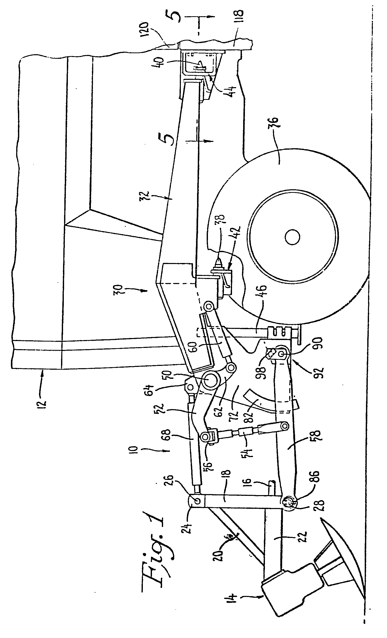
Figure 1 is a side elevational view of a portion of a tractor on which the front implement
hitch of the present invention has been mounted;
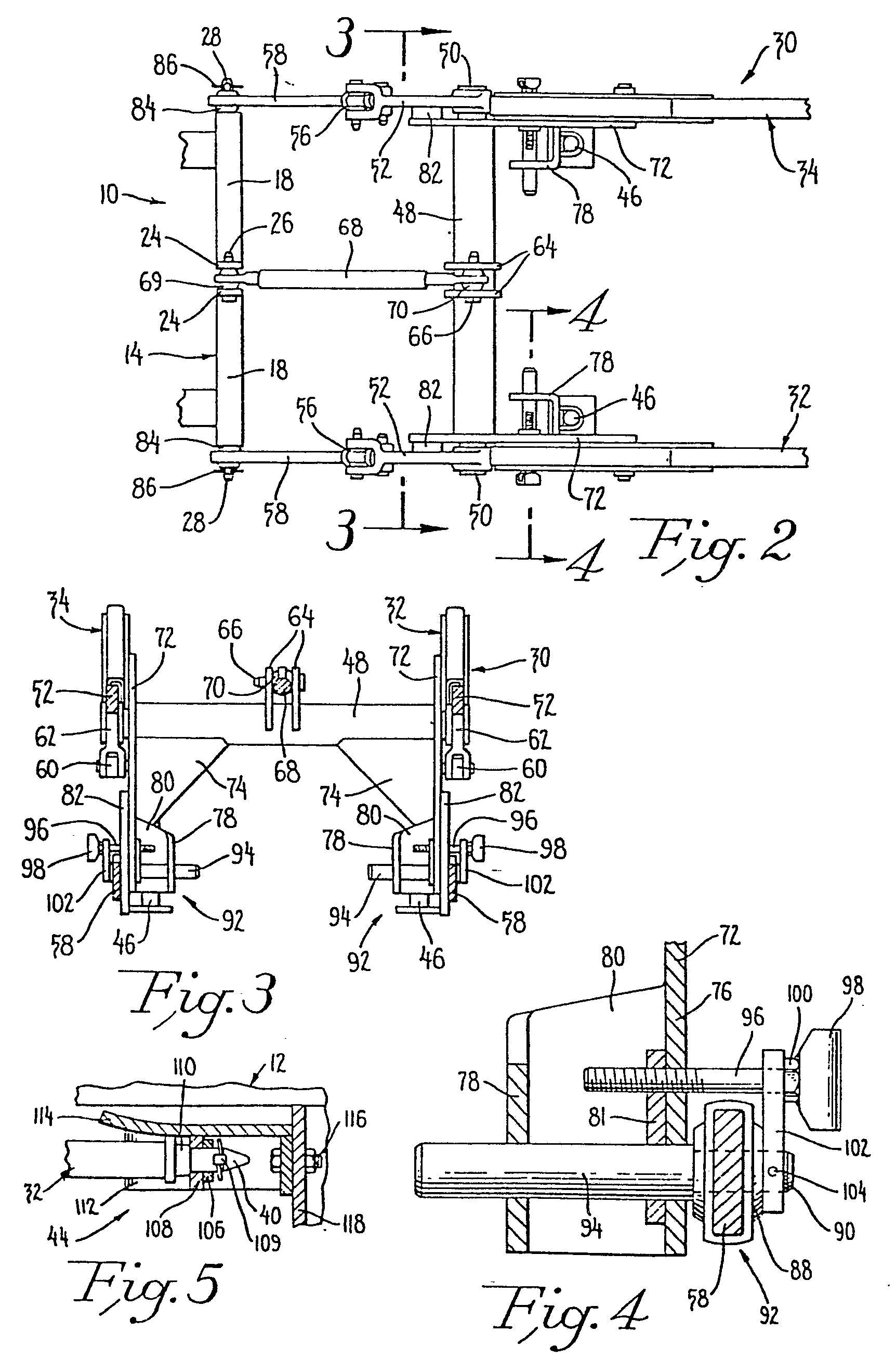
Figure 2 is a plan view of a portion of the front implement hitch associated with
an implement, but not with a tractor;
Figure 3 is a front sectional view taken generally along the line 3-3 of Figure 2;
Figure 4 is a front sectional view taken generally along the lines 4-4 in Figure 2;
and
Figure 5 is a sectional view taken along the lines 5-5 in Figure 1.
Best Mode of Carrying Out Invention
[0016] Referring now to Figure 1, the front implement hitch is indicated generally at 10.
It is illustrated mounted on the front portion of a tractor 12, the hitch carrying
an implement indicated generally at 14. While a beet topper is shown in Figure 1 (which
beet topper would be driven from a PTO shaft 16), various other implements may be
mounted forwardly of a tractor. Such implements include mowers, rakes, tedders, cultivators,
etc. These implements would be of a type which are adapted to be secured to a three-point
hitch and thus, would be provided with a mast 18 and a strut 20, one end of which
is supported on the implement frame 22. The mast 18 will be provided with a pair of
spaced apart ears 24 which receive a transversely extending pin 26. The implement
will also be provided with a crossbar terminating at either end in transversely extending
spaced apart hitch pins 28.
[0017] The farm equipment industry has adopted various standard sized of three-point hitch
implements in which the spacing between the hitch pins will vary as well as various
other features. It is a feature of this invention to provide a tractor implement hitch
which can be secured to differing category implements having differing spacings between
the transversely extending hitch pins.
[0018] The tractor implement hitch 10 of the invention includes a generally U-shaped support
frame indicated at 30. As can best be seen from Figures 1 and 2 the support frame
includes spaced apart generally parallel longitudinally extending left and right hand
legs 32, 34, which legs are adapted to be disposed on opposite sides of the front
portion of tractor 12, such legs extending over the axle for the forward wheels 36.
Each of the legs, which are formed of box beam sections, is provided with front and
rear quick-attach bayonet mounting pins 38, 40 which extend generally longitudinal
of the hitch and are adapted to be secured to complementary mounting portions 42,
44 of the tractor. A stand 46 (shown in Figure 1 in its raised inoperative position)
is carried by each of the legs 32, 34. The stands are provided to facilitate the mounting
of the frame. The mounting of the frame will be discussed in greater detail below.
[0019] In addition to the spaced apart legs 32, 34 the frame 30 is provided with a transverse
member in the form of a hollow tube 48, the hollow tube being welded or otherwise
rigidly secured to the forward ends of the pair of legs 32, 34. A rock shaft 50 extends
through the hollow tube 48, the rock shaft being provided with lift arms 52 at either
end. The upper ends of a pair of vertically adjustable lift links 54 are connected
to the pair of lift arms 52 by universal joint connections indicated generally at
56. The lower end of each of the lift links 54 is secured to an intermediate portion
of an associated lower link 58.
[0020] An extensible and retractable force applying means in the form of a hydraulic cylinder
assembly 60 has its anchor end pivotally secured to one portion of the frame, and
its rod end secured to an extension 62 of one of the lift arms 52. It should be obvious
that if the cylinder were extended both lift arms 52 would be raised, which in turn
acting through the lift links 54 would cause the lower links 58 to be raised.
[0021] Mounted upon an intermediate portion of the hollow tube 48 is a pair of upwardly
extending ears 64 which receive a transversely extending pin 66. An upper link 68
is provided with front and rear apertured balls 69, 70.
[0022] The upper link 68 is mounted with the pin 26 passing through the forward ball 69
and the pin 66 passing through the rear ball 70.
[0023] The frame 30 further includes generally parallel spaced apart members or plates 72
each of which is secured to a forward portion of one of the legs 32, 34 and also to
the hollow tube 48 by reinforcing piates 74. The lower rear portion of each of the
plates 72 is bent into a U-, shape having an outer portion 76, an inner portion 78,
and a bight portion 80 (Figure 4). A reinforcing portion 81 is secured to the inner
surface of the outer portion 76. The outer surface of each plate supports a rub block
82 which is engageable by an intermediate portion of an associated lower link 58 to
limit its sway. Each of the rub blocks or spaced apart devices 82 is disposed between
the lift links 54 and the rear end of the lower link 58.
[0024] Each of the links 58 is provided with apertured balls rotatably mounted on its front
and rear ends. The forward ball 84 is adapted to be positioned over one of the hitch
pins 28 and secured in place by a lynchpin 86. The rear ball 88 is mounted on a laterally
shiftable pin 90, there being one pin 90 for each of the lower links 58, and each
of the pins 90 forming part of one of a pair of spaced apart adjustable mounting means
indicated generally at 92. The pin 90 is an extension of a round bar 94 which passes
through transversely aligned apertures in the inner and outer portions 76, 78 of the
U-shaped portion of the plate 72 as well as the reinforcing portion 81. The outer
portion 76 and reinforcing portion 81 are also provided with aligned threaded apertures
which receive a threaded member in the form of a bolt 96, the bolt being parallel
to the pin 90 and bar 94. In the embodiment illustrated, a handle 98 has been welded
to the head 100 of the bolt 96. An intermediate member in the form of a strap 102
interconnects the bolt 96 with the pin 90. Thus, one end of the strap 102 is journalled
about the bolt 96 but is restrained from outward movement relative thereto by the
bolt head 100. The other end of the strap 102 is secured to the outer end of the pin
90 by a roll or pin 104 of comparable securing means. As can be seen from Figure 4,
a shoulder is formed between the pin 90 and bar 94. One side of the ball 88 is disposed
adjacent to this shoulder and the other side of the ball 88 is disposed adjacent one
side of the strap 102. Thus the ball 88 cannot move relative to the pin 90. As will
be obvious from the construction illustrated in Figure 4 as the handle 98 is rotated
in a clockwise direction the strap 102 will be forced toward the portion 76 causing
the pin 90 and ball 88 to be shifted inwardly. Alternatively, if the handle 98 is
rotated in a counterclockwise direction, the strap 102 will be permitted to shift
outwardly along with the ball 88.
[0025] When the parts are assembled in the manner illustrated in the various figures, it
should be apparent that as the handle 98 is rotated to move the pin 90 towards the
centre that an intermediate portion of the lower link 58 will be caused to bear against
the rub block 82 as outward movement of the forward ball 84 is constrained from such
movement by the lynchpin 86. Thus, by adjusting the right and left spaced apart adjusting
means towards each other the implement 14 mounted upon the tractor implement hitch
of this invention may be secured in such a manner that all side to side sway is eliminated.
Alternatively small or controlled amounts of side to side sway may be permitted. Furthermore,
as the forward ends of the lower links can be moved outwardly without affecting the
disposition of the adjustable mounting means 92, implements can be readily mounted
on the hitch.
[0026] To remove the implement from a tractor it is necessary to lower the stands 46 until
they engage the ground. The hydraulic lines (not shown) to the cylinder assembly 60
are disconnected, and the lynchpins 109 used to secure the bayonet mounting pins to
the mounting portions are removed. The tractor and hitch are then separated by either
levering the unit off the tractor, or by backing off the tractor. As the stands are
located near the balance point of the hitch, the hitch 10 can easily be parked tilted
on the stands 46 and lower links 58. The procedure for attachment is essentially the
opposite of detachment. Thus, the tractor is driven between the arms 22, 34 so that
the bayonet pins pass through apertures in transverse portion 108 and reinforcing
number 106 until the collars 110 about the pins 38 or 40 abut the forward surface
of the transverse portion 108 of the mounting portions. The bayonet pins are guided
into these apertures by lower and side guide plates 112, 114 which engage a portion
of the leg 32, 34 adjacent the corresponding bayonet pin, the stands 46 assisting
in positioning the pins 38, 40 at the correct height for engagement in the apertures.
Once the collars 110 are in proper engagement, the bayonets are secured in place by
the lynchpins 109, it being customary to employ one lynchpin on each side of the tractor.
[0027] While only the left rear mounting portion is shown in Figure 5, it should be obvious
that the right rear portion is essentially the same with the side guide 114 disposed
between the leg 34 and the tractor 12. The rear mounting portions are secured by nut
and bolt assemblies 116 to that portion of the tractor frame 118 which supports the
forward portion of the cab 120. The forward mounting portions 42 correspond generally
to the rear portions 44 and are secured to the tractor 12 in a manner not illustrated.
[0028] It is not necessary to remove an implement from the hitch before the hitch is removed.
Thus, the tractor implement hitch could be parked on the implement and stands, and
the top link could be used to adjust the height of the rear mounting pins.
[0029] As will be appreciated, since the quick-attach bayonet pins 38, 40 form the sole
support for the hitch on the tractor the hitch can be readily attached to and removed
from the tractor by the simple drive-in or drive-out procedure described above and
the inseption or removal of the lynchpins 109.
[0030] It will be clear that a number of modifications can be made to the construction described
above without departing from the scope of the present invention. For example, the
hitch could employ four links, two lower links and two upper links, instead of the
three link arrangement described above.
[0031] Also, in the three link arrangement described above only one of the lower links may
be adjust- ably mounted on the frame. Such a construction, although probably less
desirable, would still enable the lateral spacing between the rear ends of the lower
links to be adjusted.
1. A front implement hitch (10) for mounting an implement (14) forwardly of a tractor
(12), the hitch including a pair of laterally spaced apart lower links (58) arranged
to extend forwardly of the tractor when in use, the forward ends of the lower links
being provided with attachment means for the implement and being movable vertically
and swingable from side to side, and a pair of laterally spaced apart mounting means
(92) associated with the tractor for mounting the rear ends of the lower links, said
hitch being characterized in that at least one of the mounting means includes adjustment
means (90, 94, 96, 102) for adjusting the lateral spacing between the rear ends of
the lower links, and in that a pair of vertical rubbing surfaces (82) are provided
on the hitch for abutment with an intermediate portion of the lower links to limit
the side to side sway of the lower links.
2. A front hitch according to claim 1 characterized in that the adjustment means (90,
94, 96, 102) enables the lateral spacing between the rear ends of the lower links
(58) to be adjusted in a stepless manner.
3. A front hitch according to claim 1 or claim 2 further characterized by the provision
of a U-shaped support frame (30) including a pair of spaced apart generally parallel
legs (32, 34) adapted to be disposed on either side of the tractor (12) and secured
thereto, and a transverse member (48) adapted to be disposed forwardly of the tractor
when said pair of legs are secured to the tractor, said transverse member being interconnected
with the forward ends of said pair of legs, and said mounting means (92) and said
rubbing surfaces (82) being carried from said support frame (30).
4. A front hitch according to claim 3 further characterized in that said transverse
member (48) is a hollow member, said hitch (10) further including a rockshaft (50)
passing through the hollow member (48), a pair of lift arms (52) secured to the ends
of the rockshaft (50), a pair of lift links (54) extending from the pair of lift arms
(52) to the lower links (58), each of the lift links (54) being secured to an associated
lower link (58) at a location forwardly of the spaced apart mounting means (92).
5. A front hitch according to claim 4 further characterized by the provison of extensible
and retractable force applying means (60) extending between one of the pair of legs
(32) and one of the lift arms (52, 62) and operable upon extension to cause said lower
links (58) to be raised.
6. A front hitch according to claim 4 or 5 further characterized in that a pair of
spaced apart ears (64) are secured to the hollow member (48) midway between its ends,
and also in that an upper link (68) is secured between the spaced apart ears (64).
7. A front hitch according to any preceding claim further characterized in that said
support frame (30) includes a pair of generally parallel members (72) disposed between
the lower links (58) and in that the vertical rubbing surfaces (82) are rub blocks,
there being one rub block (82) mounted on each of the parallel members (72) in such
a position that it may be contacted by an intermediate portion of an associated lower
link (58).
8. A front hitch according to any preceding claim further characterized in that at
least one of the lower links (58) includes an apertured mounting ball (88) at its
rear end, and in that the associated adjustment means (90, 94, 96) includes a laterally
shiftable pin (90, 94) which receives the mounting ball.
9. A front hitch according to claim 8 when dependent on claim 3 further characterized
in that the adjustment means (90, 94, 96) includes a rotatable threaded member (96)
mounted parallel to the laterally shiftable pin (90, 94), said threaded member passing
through a threaded aperture within the support frame (30, 72), and in that an interconnecting
member (102) interconnects said pin (90, 94) with the threaded member (96) to affect
movement of said pin (90, 94) when said threaded member (102) is rotated relative
to the threaded aperture.
10. A front hitch according to claim 9 further characterized in that the rear end
of each lower link (58) is provided with ah apertured mounting ball (88) and a threaded
member (96), and a laterally shiftable pin (90, 94) is associated with each apertured
mounting ball whereby each of the lower links can be independently adjusted.
11. A front hitch according to any one of claims 3 to 10 further characterized in
that the support frame (30) is provided with quick-attach formations in the form of
projections (38, 40) or apertured plates (42, 44) for engagement with complementary
apertured plates or projections on the tractor to serve as the sole support for the
frame on the tractor, the projections being arranged to extend generally longitudinally
of the hitch and the apertured plates generally transversely thereto so that the projections
and apertures can be engaged by forward motion of the tractor relative to the hitch.
12. A front implement hitch for attachment to the front portion of a tractor (12),
said hitch including a generally U-shaped support frame (30, 32, 48, 34) for embracing
the front and sides of said front portion, a pair of lower implement support links
(58) and at least one upper implement support links (68), all the links being supported
from the frame and extending forwardly thereof for generally vertical pivotal movement
relative thereto, implement attachment means (84) at the forward ends of all the links,
lifting means (50, 52, 54, 60, 62) supported from the frame for pivoting said lower
links (58) relative thereto and a plurality of support means (38, 40) on the support
frame (30) for engagement with complementary support means (42, 44) on the front portion
of the tractor (12), said hitch being characterized in that the support means comprise
a plurality.of projections (38, 40) or apertured mounting plates (42, 44) on the support
frame (30) which are arranged to inter-engage corresponding apertured mounting plates
or projections on the tractor (12), the projections being arranged to extend generally
longitudinally of the hitch and the apertured plates (42, 44) generally transversely
thereto so that the projections and apertures can be engaged by forward motion of
the tractor relative to the hitch, locking means (109) being provided to retain the
projections (38, 40) and apertures in engagement during use of the hitch, the lower
links (58) being supported at their rear ends from the frame (30, 32, 34, 48) with
limited sway by laterally spaced mounting means (92), at least one of the mounting
means including adjustment means (90, 94, 96, 102) for adjusting the lateral spacing
between the rear ends of the lower links, and a pair of generally vertical rubbing
surfaces (82) being provided for abutment with an intermediate portion of the lower
links to limit the side to side sway of the lower links.
13. A front hitch according to claim 11 or 12 further characterized in that a stand
(46) is provided for assisting in positioning the projections (38, 40) and apertured
plates (42, 44) at the correct relative height for interengagement and in that guidance
means (112, 114) are provided to position the projections and apertured plates for
automatic drive-in engagement.
1. Accouplement d'attelage AV (10) d'accessoire pour monter un accessoire (14) à l'AV
d'un tracteur (12), l'accouplement comportant une paire de raccords inférieurs (58)
écartés de manière à sortir à l'AV du tracteur en service, l'extrêmité AV des raccords
inférieurs étant munie de moyens d'attelage d'accessoire et admettant une course verticale
ainsi que le pivotement d'un côté à l'autre, et une paire de moyens de pose (92) également
écartés associés avec le tracteur pour monter les extrémités AR des raccords inférieurs,
ledit attelage étant caractérisé en ce qu'un des moyens de pose (92) au moins comporte
des facilités de réglage (90, 94, 96, 102) permettant d'ajuster l'écart entre les
extrémités AR des raccords inférieurs et en ce qu'une paire de surfaces verticales
de friction (82) sont prévues sur l'attelage pour venir en butée avec une tranche
intermédiaire des raccords inférieurs de manière à limiter le balancement latéral
des raccords inférieurs.
2. Accouplement d'attelage AV selon la revendication 1 caractérisé en ce que les facilités
de réglage (90, 94, 96, 102) permettent le réglage continu de l'écartement des extrémités
AR de raccords inférieurs (58).
3. Accouplement d'attelage AV selon la revendication 1 ou la revendication 2 également
caractérisé par un bâti de support en U (30) comportant une paire d'éléments écartés
et généralement parallèles (32, 34) adaptés pour l'aménagement et la fixation de chaque
côté du tracteur (12) et un élément transversal (48) agencé pour la pose à l'AV du
tracteur lorsque la paire d'éléments est fixée au tracteur, ledit élément transversal
étant raccordé avec les extrémités AV de ladite paire d'éléments, lesdits moyens de
pose (92) et lesdites surfaces de friction. (82) étant portés par ledit bâti de support
(30).
4. Accouplement d'attelage AV selon la revendication 3 également caractérisé en ce
que ledit élément transversal (48) est un élément creux, ledit attelage (10) comportant
également un essieu balancier (50) passant par l'élément creux (48), une paire de
bras de levage (52) fixée aux extrémités du balancier (50), une paire de raccords
de levage (54) étant agencée en prolongation de la paire de bras de levage (52) sur
les raccords inférieurs (58), chacun des raccords de levage (54) étant fixé à un raccord
inférieur associé (58) en un point situé à l'AV des moyens de pose écartés (92).
5. Accouplement d'attelage AV selon la revendication 4 également caractérisé par des
moyens à course d'extension et de retour d'application de force (60) avancés entre
un seul de la paire d'éléments (32) et un des éléments de levage (52, 62) et dont
la fonction en avancement est de provoquer le levage desdits raccords inférieurs (58).
6. Accouplement d'attelage AV selon la revendication 4 ou 5 également caractérisé
en ce qu'une paire d'oreilles écartées (64) est fixée à l'élément creux (48) à mi-chemin
entre ses extrémités, et en ce qu'un raccord supérieur (68) est fixé entre les oreilles
écartées (64).
7. Accouplement d'attelage AV selon l'une des revendications précédentes caractérisé
en ce que ledit bâti de support (30) comporte une paire d'éléments essentiellement
parallèles (72) disposés entre les raccords inférieurs (58) et en ce que les surfaces
verticales de friction (82) sont des blocs de friction, dont un bloc de friction (82)
est monté sur chacun des éléments parallèles (72) de telle manière à permettre le
contact éventuel avec une tranche intermédiaire d'un raccord inférieur associé (58).
8. Accouplement d'attelage AV selon l'une des revendications précédentes caractérisé
en ce qu'un des raccords inférieurs (58) au moins comporte une boule de pose à ouverture
(88) située à l'extrêmité AR et en ce que les moyens associés de réglage (90, 94,
96) comportant un axe admettant le déplacement latéral (90, 94) recevant la boule
de pose.
9. Accouplement d'attelage AV selon la revendication 8 sous réserve de la revendication
3 également caractérisé en ce que les moyens de réglage (90, 94, 96) comportent un
élément fileté rotatif (96) monté parallèle à l'axe de déplacement latéral (90, 94),
ledit élément fileté passant par une ouverture filetée dans le bâti de support (30,
72) et en ce qu'un élément de raccord (102) assure le raccord dudit axe (90, 94) avec
l'élément fileté (96) afin d'influencer le mouvement dudit axe (90, 94) lors de la
rotation dudit élément (102) par rapport à l'ouverture filetée.
10. Accouplement d'attelage AV selon la revendication 9 également caractérisé en ce
que l'extrêmité AR de chaque raccord inférieur (58) comporte une boule à ouverture
de montage (88) et un élément fileté (96) et un axe à déplacement latéral (90, 94)
associé avec chaque boule à ouverture de montage, permettant le réglage indépendant
de chacun des raccords inférieurs.
11. Accouplement d'attelage AV selon l'une des revendications 3 à 10 également caractérisé
en ce que le bâti de support (30) comporte des formes d'attelage rapide assurées par
des éléments en saillie (38, 40) ou plaques à ouverture (42, 44) permettant l'engrènement
avec des plaques à ouverture ou éléments en saillie complémentaires sur le tracteur
servant de support unique du bâti sur le tracteur, les éléments en saillie étant disposés
pour avancer essentiellement dans le sens longitudinal de l'attelage et les plaques
à ouverture étant disposées dans le sens transversal, de manière que les éléments
en saillie et les ouvertures admettent l'engrènement par le mouvement en AV du tracteur
par rapport à l'attelage.
12. Accouplement d'attelage AV d'accessoire à l'AV d'un tracteur (12), ledit attelage
comportant un bâti de support essentiellement en U (30, 32, 48, 34) pour entourer
les côtés et le front de ladite tranche AV, une paire de raccords inférieurs de support
d'accessoire (58) et au moins un raccord supérieur de support d'accessoire (68), tous
les raccords étant supportés depuis le bâti et avancés relativement en AV pour permettre
le mouvement essentiellement vertical de pivotement en relation, les moyens d'attelage
d'accessoire (84) aux extrêmités AV de tous les raccords, des moyens de levage (50,
52, 54, 60, 62) supportés à partir du bâti pour pivoter lesdits raccords inférieurs
(58) en relation et plusieurs moyens de support (38, 40) sur le bâti de support (30)
permettant l'engrènement avec des moyens complémentaires de support (42, 44) sur le
plan AV du tracteur (12), ledit attelage étant caractérisé en ce que les moyens de
support comportent plusieurs éléments en saillie (38, 40) ou des plaques de pose à
ouverture (42, 44) sur le bâti (30), disposés pour le raccord et engrènement avec
des plaques de pose à ouverture ou éléments en saillie de forme correspondante sur
le tracteur (12), les éléments en saillie étant disposés de manière à s'avancer essentiellement
dans le sens longitudinal de l'attelage et les plaques à ouverture (42, 44) essentiellement
dans le sens transversal de manière à permettre l'engrènement des éléments en saillie
et does ouvertures par un mouvement en avant du tracteur par rapport à l'attelage,
des moyens de blocage (109) étant prévus pour retenir les éléments en saillie (38,
40) et les ouvertures engagées lors de la mise en oeuvre de l'attelage, les raccords
inférieurs (58) étant supportés aux extrémités AR depuis le bâti (30, 32, 34, 38)
avec un balancement limité par des moyens de pose écartés (92), un des éléments de
pose au moins comportant des facilités de réglage (90, 94, 96, 102) pour ajuster l'écart
entre les extrêmités AR de raccords inférieurs, et une paire de surfaces de friction
(82) essentiellement verticales étant prévue pour venir en butée avec une tranche
intermédiaire des raccords inférieurs pour limiter le balancement latéral des raccords
inférieurs.
13. Accouplement d'attelage AV selon la revendication 11 ou 12 également caractérisée
par une béquille (46) prévue pour faciliter le réglage des éléments en saillie (38,
40) et des plaques à ouverture (42, 44) au niveau recherché pour permettre l'engrènement,
des moyens de de guidage (112, 114) étant prévus pour ajuster les éléments en saillie
et les plaques à ouverture pour l'engagement automatique lors du mouvement en AV de
tracteur.
1. Frontanbauvorrichtung (10) für die Montage eines Geräts (14) vorne an einer Zugmaschine
(12), bestehend aus einem Paar seitlich im Abstand voneinander angeordneten unteren
Verbindungsgliedern (58), die so angeordnet sind, daß sie im Einsatz nach vorne ausgefahren
sind, wobei die Vorderenden der unteren Verbindungsglieder mit Befestigungsmitteln
für das Gerät ausgestattet und lotrecht und seitlich schwenkbar angeordnet sind, und
einem Paar seitlich im Abstand voneinander angeordneten, zur Zugmaschine gehörenden
Befestigungsmitteln (92) zur Befestigung der Hinterenden der unteren Verbindungsglieder,
dadurch gekennzeichnet, daß wenigstens eines der Befestigungsmittel Justiervorrichtungen
(90, 94, 96, 102) für die Justierung des seitlichen Abstandes zwischen den hinteren
Enden der unteren Verbindungsglieder besitzt und daß ein Paar lotrechter Reibflächen
(82) an der Anbauvorrichtung als Anschlag für das Zwischenstück der unteren Verbindungsglieder
zur Begrenzung der seitlichen Schwenkbewegung der unteren Verbindungsglieder vorgesehen
sind.
2. Frontanbauvorrichtung nach Anspruch 1, dadurch gekennzeichnet, daß die Justiervorrichtungen
(90, 94, 96, 102) eine stufenlose Justierung des seitlichen Abstandes der hinteren
Enden der unteren Verbindungsglieder (58) erlauben.
3. Frontanbauvorrichtung nach Anspruch 1 oder 2, weiter gekennzeichnet durch das Vorhandensein
eines U-förmigen Stützrahmens (30) einschließlich eines Paares von im Abstand voneinander
angeordneten, im wesentlichen parallel zueinander verlaufenden Beinen (32, 34), die
so ausgebildet sind, daß sie sich auf den beiden Seiten der Zugmaschine (12) anordnen
und an ihr befestigen lassen, sowie durch ein quer verlaufendes Verbindungsglied (48),
daß so ausgelegt ist, daß es sich vorne an der Zugmaschine anordnen läßt, wenn besagte
Beine an der Zugmaschine befestigt sind, wobei besagtes querverlaufendes Verbindungsglied
mit den Vorderenden des besagten Beinepaares in Verbindung steht und besagte Befestigungsmittel
(92) und die besagten Reibflächen (82) an dem besagten Stützrahmen abgestützt sind.
4. Frontanbauvorrichtung nach Anspruch 3, weiter dadurch gekennzeichnet, daß besagtes
Querglied (48) als Hohlteil ausgebildet ist, wobei besagte Anbauvorrichtung (10) auch
eine Schwingwelle (50) aufweist, die sich durch das Hohlglied (48) erstreckt, sowie
ein Paar Hebearme (52), die am Ende der Schwingwelle (50) montiert sind, und ein Paar
Hebeglieder (54), die sich von dem Hebearmepaar (52) bis zu den unteren Verbindungsgliedern
(58) erstrecken, wobei jedes der Hebeglieder (54) an einem zugehörigen unteren Verbindungsglied
(58) vor den im Abstand angeordneten Befestigungsmitteln (92) befestigt ist.
5. Frontanbauvorrichtung nach Anspruch 3, weiter gekennzeichnet durch das Vorhandensein
eines aus- und einfahrbaren Kraftbeaufschlagungsmittels (60), das sich zwischen einem
Bein des Beinepaares (32) und einem der Hebearme (52, 62) erstreckt und beim Ausfahren
so bedient werden kann, daß die besagten unteren Verbindungsglieder (58) gehoben werden.
6. Frontanbauvorrichtung nach Anspruch 4 oder 4, weiter dadurch gekennzeichnet, daß
ein Paar im Abstand voneinander angeordnete Backen (64) an dem Hohlglied (48) mittig
zwischen dessen Enden angeordnet sind, und daß ein oberes Verbindungsglied (68) zwischen
den im Abstand voneinander angeordneten Backen (64) befestigt ist.
7. Frontanbauvorrichtung gemäß einem der obigen Ansprüche, weiter dadurch gekennzeichnet,
daß besagter Stützrahmen (30) ein Paar im wesentlichen parallel zueinander verlaufende
Träger (72) aufweist, die zwischen den unteren Verbindungsgliedern (58) angeordnet
sind und daß die lotrechten Reibflächen (82) Reibklötze sind, wobei jeweils ein Reibklotz
(82) auf jedem der parallel zueinander verlaufenden Träger in einer solchen Lage montiert
ist, daß er von einem Zwischenteil eines zugehörigen unteren Verbindungsgliedes berührt
werden kann.
8. Frontanbauvorrichtung gemäß einem der obigen Ansprüche, weiter dadurch gekennzeichnet,
daß wenigstens eines der unteren Verbindungsglieder (58) an seinem hinteren Ende eine
mit Öffnungen versehene Lagerkugel (88) aufweist und daß die zugehörigen Justiermittel
(90, 94, 96) einen in Querrichtung verstellbaren Zapfen (90, 94) mit einschließen,
der die Lagerkugel aufnimmt.
9. Frontanbauvorrichtung nach Anspruch 8, in Abhängigkeit von Anspruch 3 dadurch weiter
gekennzeichnet, daß die Justiermittel (90, 94, 96) ein drehbares Gewindeteil (96)
aufweisen, das parallel zu dem in Querrichtung verstellbaren Zapfen (90, 94) verläuft,
wobei besagtes Gewindeteil durch eine Gewindöffnung im Stützrahmen (30, 72) reicht
und daß ein Verbindungsglied (102) besagten Zapfen (90, 94) so mit dem Gewindeteil
(96) verbindet, daß eine Bewegung des besagten Zapfens (90, 94) verursacht wird, wenn
besagtes Gewindeteil (102) relativ zu der Gewindeöffnung gedreht wird.
10. Frontanbauvorrichtung nach Anspruch 9, dadurch weiter gekennzeichnet, daß an dem
rückwärtigen Ende eines jeden unteren Verbindungsgliedes (58) eine mit Öffnungen versehene
Lagerkugel (88) und ein Gewindeteil (96) angeordnet ist, und daß ein in Querrichtung
verstellbarer Zapfen (90, 94) zu jeder mit Öffnungen versehenen Lagerkugel zugehörig
ist, wodurch jedes der unteren Verbindungsglieder unabhängig justierbar ist.
11. Frontanbauvorrichtung gemäß einem der Ansprüche 3 bis 10, dadurch weiter gekennzeichnet,
daß der Stützrahmen (30) mit Schnellmontageansätzen in Form von Vorsprüngen (38,'
40) oder Platten mit Öffnungen (42, 44) ausgestattet ist, die in passende Platten
mit Öffnungen oder Vorsprünge an der Zugmaschine eingreifen und als einzige Abstützung
des Stützrahmens an der Zugmaschine dienen, wobei die Vorsprünge so angeordnet sind,
daß sie im wesentlichen längs zur Anbauvorrichtung verlaufen, während die Platten
mit Öffnungen im wesentlichen quer zu ihnen so verlaufen, daß die Vorsprünge und und
Öffnungen durch Vorwärtsbewegung der Zugmaschine relativ zur Anbauvorrichtung miteinander
in Eingriff gebracht werden können.
12. Frontanbauvorrichtung für die Montage am Vorderende einer Zugmaschine (12), wobei
besagte Anbauvorrichtung einen im wesentlichen U-förmigen Stützrahmen (30, 32, 48,
34) mit einschließt, der das Vorderende und die Seiten des besagten Vorderteils umgreift,
sowie ein Paar untere Geräte-Stützglieder (58) und wenigstens ein oberes Geräte-Stützglied
(68), wobei alle diese Glieder am Stützrahmen abgestützt sind und sich von diesem
zur Erzielung einer im wesentlichen lotrecht verlaufenden Kippbewegung gegenüber dem
besagten Stützrahmen nach vorne erstrecken, Mittel (84) zum Anbringen von Geräten
an den Vorderenden sämtliche Verbindungsglieder, Hebemittel (50, 52, 54, 60, 62),
die am Stützrahmen abgestützt sind, um die besagten unteren Verbindungsglieder (58)
relativ zu ihm abzukippen, sowie eine Vielzahl von Stützmitteln (38, 40) am Stützrahmen
(30) für den Eingriff in passende Stützmittel (42, 44) vorne an der Zugmaschine (12),
dadurch gekennzeichnet, daß bei besagter Frontanbauvorrichtung die Stützmittel aus
einer Vielzahl von Vorsprüngen (38, 40) oder am Rahmen (30) angebrachten, mit Öffnungen
versehenen Stützplatten (42, 44) bestehen, die so angeordnet sind, daß sie in entsprechende,
passende Montageplatten oder Vorsprünge an der Zugmaschine (12) eingreifen, wobei
diese Vorsprünge so angeordnet sind, daß sie im wesentlichen in Längsrichtung zur
Frontanbauvorrichtung verlaufen, während die mit Öffnungen versehenen Platten (42,
44) im wesentlichen quer verlaufen, so daß die Vorsprünge und Öffnungen durch Vorwärtsfahren
der Zugmaschine relativ zur Anbauvorrichtung miteinander in Eingriff gebracht werden
können und wobei Verriegelungsmittel (109) auf solche Art und Weise angebracht sind,
daß die Vorsprünge und Öffnungen während der Benutzung der Anbauvorrichtung in Eingriff
gehalten werden, indem die unteren Verbindungsglieder (58) an ihren rückwärtigen Enden
am Rahmen (30, 32, 34, 48) abgestützt sind und sich durch die seitlich im Abstand
angeordneten Montagevorrichtungen (92) nur beschränkt bewegen können, und wenigstens
eine der besagten Montagevorrichtungen (92) mit Justiermitteln (90, 94, 96, 102) ausgestattet
ist, mit denen der Querabstand zwischen den hinteren Enden der unteren Verbindungsglieder
eingestellt werden kann, und durch ein Paar im wesentlichen lotrecht verlaufenden
Reibflächen (82) als Stoßfläche für einen Mittelteil der unteren Verbindungsglieder
zur Begrenzung der seitlichen Schwingung der unteren Verbindungsglieder.
13. Frontanbauvorrichtung nach Anspruch 11 oder 12, dadurch weiter gekennzeichnet,
daß ein Ständer (46) für die Erleichterung der Einstellung der Vorsprünge (38, 40)
und der mit Öffnungen versehenen Platten (42, 44) in der korrekten relativen Höhe
vorgesehen ist und daß Führungsmittel (112, 114) vorgesehen sind, um die Vorsprünge
und mit Öffnungen versehenen Platten durch Anfahren der Zugmaschine automatisch miteinander
in Eingriff zu bringen.