| (19) |
 |
|
(11) |
EP 0 022 378 B1 |
| (12) |
EUROPEAN PATENT SPECIFICATION |
| (45) |
Mention of the grant of the patent: |
|
25.05.1983 Bulletin 1983/21 |
| (22) |
Date of filing: 10.07.1980 |
|
| (51) |
International Patent Classification (IPC)3: A45C 13/26 |
|
| (54) |
Luggage case handle assembly
Traggriff für Handgepäck
Poignée pour valise
|
| (84) |
Designated Contracting States: |
|
BE CH DE FR GB IT LI LU NL SE |
| (30) |
Priority: |
10.07.1979 US 56207
|
| (43) |
Date of publication of application: |
|
14.01.1981 Bulletin 1981/02 |
| (71) |
Applicant: SAMSONITE CORPORATION |
|
Denver, Colorado 80239 (US) |
|
| (72) |
Inventors: |
|
- Burzen, Don N.
Groton
Massachusetts (US)
- Bromley, Robert L.
Aurora, Colorado 80012 (US)
- Elles, Daniel G.
Kittredge
Colorado (US)
- Wilkuski, James E.
Evergreen
Colorado (US)
- Workman, David E.
Evergreen
Colorado (US)
|
| (74) |
Representative: Brereton, Paul Arthur et al |
|
REDDIE & GROSE
16 Theobalds Road
London WC1X 8PL
London WC1X 8PL (GB) |
|
| |
|
| Note: Within nine months from the publication of the mention of the grant of the European
patent, any person may give notice to the European Patent Office of opposition to
the European patent
granted. Notice of opposition shall be filed in a written reasoned statement. It shall
not be deemed to
have been filed until the opposition fee has been paid. (Art. 99(1) European Patent
Convention).
|
[0001] The present invention relates generally to a handle assembly, and, more particulariy,
to an improved luggage case, handle assembly.
[0002] U.S. Patent Specification No. 3430742 describes a luggage case handle assembly comprising
an elongate gripping member having a pair of mutually-spaced longitudinally-extending
grooves in its surface and first and second longitudinally-directed openings in respective
opposite ends. A one piece metal cover has longitudinal edges received in the grooves
in the gripping member. First and second stanchions for securing the handle to the
luggage case, each have a stub shaft which is received in a respective one of first
and second openings in the cover.
[0003] In the U.S. Patent Specification No. 3430742 the gripping member is formed of relatively
hard plastics material. It is the aim of the present invention to provide a handle
which is more comfortable to hold and, to this end, the gripping member is formed
of a soft compliant material. In the above-mentioned specification the gripping member
is secured to the cover by clinching or press fitting. These techniques are not suitable
for maintaining a soft compliant gripping member in place because the compliant material
will easily roll or work out of any such retaining cover.
[0004] The present invention overcomes these problems by providing a gripping member which
is of soft compliant material, by providing first and second end members having parts
received in the first and second openings in the gripping member and parts extending
in the same plane at an obtuse angle to the longitudinal axis of the gripping member
and in that the metal cover overlies the first and second end members and in that
means are provided for securing the metal cover to the first and second end members.
[0005] An embodiment of the invention will now be described by way of example with reference
to the accompanying drawings of which:-
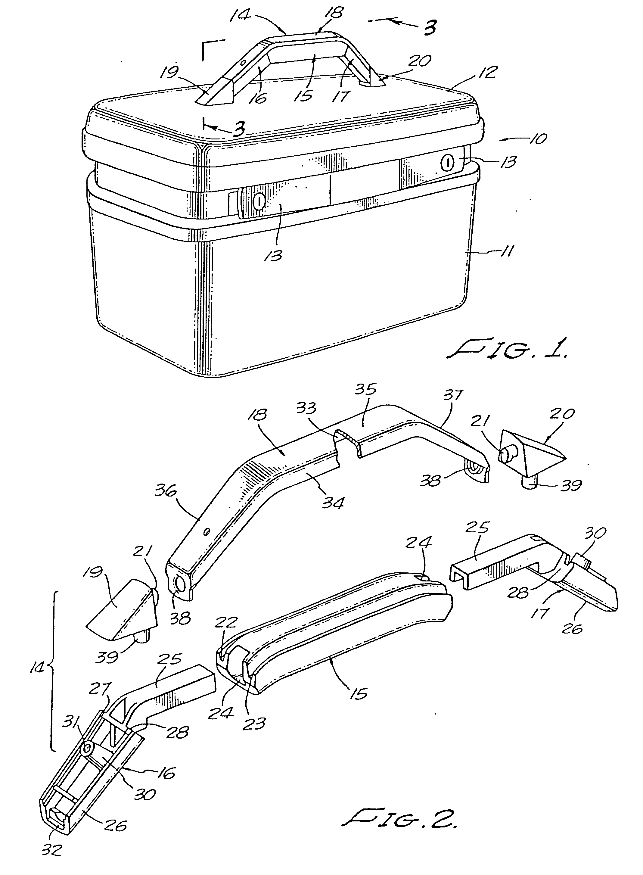
Figure 1 is a perspective view of a luggage case showing a handle assembly according
to the invention mounted thereon;
Figure 2 is an exploded view of the various parts of the handle assembly of Figure
1;
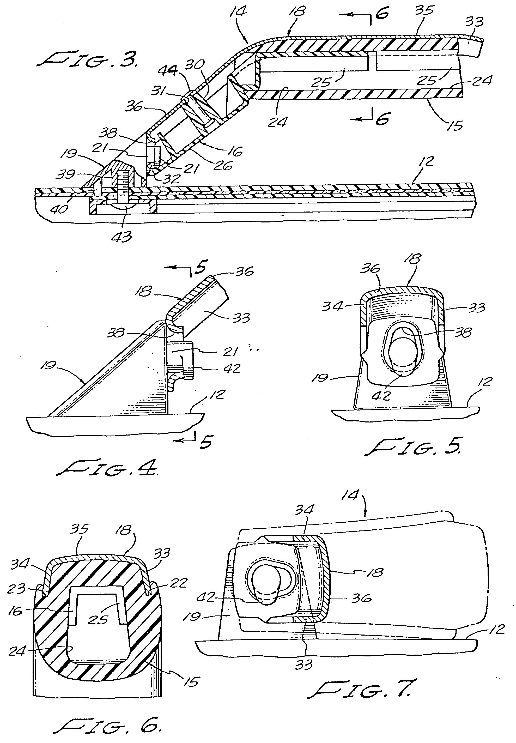
Figure 3 is an enlarged fragmentary section taken along the line 3-3 of Figure 1;
Figure 4 is an enlarged fragmentary section of the mounting stanchion of the handle
assembly of Figure 1 shown interconnected with the handle parts;
Figure 5 is a sectional end view taken along the line 5-5 of Figure 4;
Figure 6 is a sectional end view along the line 6-6 of Figure 3; and
Figure 7 is a sectional partially schematic view showing the handle assembly arranged
at 90° to that shown in Figure 5.
[0006] With reference now to Figure 1, a luggage case of the variety frequently referred
to as a train case, is identified generally as at 10, and includes a lower container
shell 11 releasably joined to a cover 12 by latches 13, for example. The handle assembly
14 to be described is secured to the top lid of the cover 12 and is seen to have a
generally trapezoidal appearance with the handle gripping portion being straight-
line and parallel to the luggage case cover, and with two end portions extending angularly
downwardly from the gripping portion of rotative securement to the cover.
[0007] Turning now to Figure 2, the handle assembly 14 is seen to include in its various
components and elongated gripping member 15, first and second end parts 16 and 17
for sliding receipt within the ends of the gripping portion, and a half-shell frame
18 received about the gripping member and two end parts unitarily securing them together.
First and second stanchions 19 and 20 are affixed to the cover 12 of the case and
each includes a stub shaft 21 which are received through openings 38 in the frame
18 for rotatably mounting the handle assembly to the cover 12.
[0008] For the ensuing description of the gripping member 15 reference is made simultaneously
to Figures 2 and 6. The member 15 is of a total length slightly greater than that
necessary to enable grasping with the four fingers of one hand. It is substantially
rectangular in cross-section with the lower corners rounded off making them more comfortable
to the grip. A pair of grooves 22 and 23 extend longitudinally along the upper surface
of the member and lying closely adjacent the outer sides thereof. The central portion
of the member between the grooves extends above the grooves and outer edge portions
of the member. An opening 24 extends completely throughout the body of the gripping
member 15 and in cross section is generally trapezoidal with the narrow width toward
the bottom. The bottom wall surface of the member 15 is a straight line, as can be
seen best in Figure 3 whereas the top wall surface is formed immediately adjacent
each end to taper downwardly a slight extent for a purpose to be described. The gripping
member is molded from flexible rubber or pliant synthetic plastic material since this
will add to the comfort of the user by being soft and pliable to the grip.
[0009] Since the end parts 16 and 17 are identical in construction, only member 16 will
be described in detail. The handle end part includes an elongate, U-shaped channel
25 which is integrally joined with a body member 26. More particularly, the channel
25 is of cross-sectional dimensions and geometry generally the same as only slightly
smaller than those of the opening 24 in the gripping member 15, thereby enabling the
channel member to be fittingly received within that opening as shown in Figure 3.
[0010] Preferably, the body member 26 extends angularly away from channel 25 (e.g., 45-90
degrees) and what is the outwardly directed surface in assembly has a pair of extended
shoulders 27 and 28 formed along the body side walls, which shoulders have a mutual
spacing substantially identical to that of the grooves 22 and 23. An upstanding mounting
post 30 has a threaded opening 31 therein for a purpose to be described. The lowermost
end of 26 is faced off at substantially 90 degrees to the channel 25 and includes
a recessed shoulder 32.
[0011] Preferably, the members 16 and 17 are of molded one-piece construction. Any one of
a number of hard plastics materials, such as acrylonitrile-butadiene-styrene (ABS)
are suitable for this purpose. Alternatively, they may be made of metal.
[0012] The frame 18 consists of a thin metal sheet stamped into a shape including a rectangular
center strip extending throughout its complete length with two side or edge walls
33 and 34. From the side, the frame is seen to have a straight line central portion
35 and two end portions 36 and 37 formed to 35 and lying in the same plane. Each outer
end of the frame end portions is faced off at 90 degrees to the central portion and
includes an opening therein to be more particularly described. The shape and dimensions
of the frame are such that the central portion side walls 33 and 34 can be received
into the grooves 22 and 23 of the gripping member with the central portion of the
frame in full intimate contact with the intervening parts of the gripping member (Figure
6). Also, these frame edge walls in the frame end portions are so dimensioned as to
permit receipt on 16 and 17 with the edges resting on shoulders 27 and 28.
[0013] As can be seen best in Figures 5 and 7, the opening 38 in each end of the frame 18
is oblong or egg-shaped with the narrow width being at the top and the broader width
at the bottom. This shape is keyed as will be described to permit a locking engagement
with parts on the stanchions 19 and 20.
[0014] The stanchions 19 and 20 are identical, therefore only 19 will be described in detail,
and is seen to include in its major aspect a generally triangular body. A cylindrical
post 39 extends out from one surface thereof for passing through an opening provided
in the top of the case cover 12 and via which the stanchion is secured by suitable
threaded member. Slightly spaced from the post 39 is a cylindrical positioning pin
40 for extending through a further opening in the cover to orient the stanchion in
a fixed predetermined manner. On a flat surface at 90 degrees to that carrying the
post 39 and pin 40, there is a stub shaft 21, the outer end of which is formed into
an oblong head 42 of geometry identical to the opening 38 in the end of member 18.
[0015] In assembly, the U-shaped channel member 25 of each end part 16, 17 is pressed into
an end opening 24 of the gripping member 15. The half-shell frame 18 is then placed
onto the gripping member and end parts with the frame edge walls 33 and 34 disposed
within grooves 22 and 23 and resting on shoulders 27 and 28. Also, the terminal end
portions of the frame are fitted into the recessed shoulders 32 of the gripping member
end portions. A rivet 44, or optionally a threaded member, extends through an opening
31 in the frame for securement in the post 30. Next, the oblong head 21 of each stanchion
is aligned and passed through a respective frame opening 38 and rotated to the locking
position shown in Figure 5. Finally, the post 39 is secured to the luggage cover top
by threaded means 43 with the positioning key 40 also properly located within a receiving
opening on the cover.
1. A luggage case handle assembly comprising an elongate gripping member (15) having
a pair of mutually-spaced longitudinally-extending grooves (22 and 23) in its surface
and first and second longitudinally-directed openings (24) in respective opposite
ends, a one-piece metal cover (18) having longitudinal edges (33 and 34) received
in the grooves (22 and 23) in the gripping member, first and second stanchions (19
and 20) for securing the handle to the luggage case (12), each stanchion (19, 20)
having a stub shaft (21) which is received in a respective one of first and second
mutually-spaced openings (38) in the cover (18), characterised in that the gripping
member (15) is of soft compliant material, in that first and second end members (16
and 17) are provided having parts (25) received in the first and second openings (24)
in the gripping member and parts (26) extending in the same plane at an obtuse angle
to the longitudinal axis of the gripping member (15), in that the metal cover (18)
overlies the first and second end members (16 and 17), and in that means (31) are
provided for securing the metal cover (18) to the first and second end members (16
and 17).
2. A luggage case handle assembly according to claim 1 characterised in that the first
and second openings (38) of the cover (18) and the terminal ends (42) of the stub
shafts (21) are of identical oblong shape so that the terminal ends (42) of the shafts
(21) can pass through the openings (38) in one orientation but are prevented from
passing through the openings (38) in other orientations.
3. A luggage case handle assembly according to claim 1 or 2 characterised in that
each end member (16 and 17) includes a pair of recessed shoulders (27 and 28) on which
the respective edges (33 and 34) of the cover (18) rest.
4. A luggage case handle assembly according to any of claims 1 to 3 characterised
in that the metal cover portions immediately surrounding the first and second openings
(38) are formed parallel to one another and are received into further recessed shoulders
(32) in the end members (16 and 17).
5. A handle assembly according to claim 2, adapted for swivelling securement to the
outer wall of a luggage case, characterised in that the elongate member (15) has a
passageway extending longitudinally therethrough which terminates at opposite ends
of the member in the first and second openings (24) respectively, in that the end
members (16 and 17) have a pair of recessed shoulders (27 and 28), in that the metal
cover (18) is elongate and of generally U-shaped cross-section the side edges (33
and 34) of which are received within the respective grooves (22 and 23) of the gripping
member (15) and recessed shoulders (27 and 28) of the end members (16 and 17), and
in that the cover (18) has its two end portions formed parallel to each other, end
portions including the first and second openings (38) in the cover being openings
which extend through the said end portions.
1. Koffergriff mit einem länglichen Griffteil (15), welches ein Paar in gegenseitigem
Abstand in Längsrichtung verlaufender Nuten (22 und 23) in seiner Oberfläche und in
einander gegenüberliegenden Enden in Längsrichtung ausgerichtete erste und zweite
Öffnungen (24) aufweist, einem einstückigen, metallenen Deckteil (18), welches sich
in Längsrichtung erstreckende Ränder (33 und 34) für die Aufnahme in den Nuten (22
und 23) des Griffteils hat, und mit ersten und zweiten Stützen (19 und 20) für die
Befestigung des Griffs an einem Koffer (12), mit jeweils einem Achsstumpf (21 ), welcher
in einer von zwei in gegenseitigem Abstand angeordneten ersten und zweiten Öffnungen
(38) des Deckteils (18) Aufnahme findet, dadurch gekennzeichnet, daß das Griffteil
(15) aus einem weichen, schmiegsamen Werkstoff ist, daß ein erstes und ein zweites
Endteil (16 und 17) vorgesehen sind, welches jeweils in den ersten und zweiten Öffnungen
(24) des Griffteils Aufnahme findende Teile (25) und sich in der gleichen Ebene wie
das Griffteil (15) in einem stumpfen Winkel zur Längsachse desselben erstrekkende
Teile (26) aufweisen, daß das metallene Deckteil (18) das erste und das zweite Endteil
(16 und 17) überdeckt und daß Einrichtungen (31) für die Befestigung des metallenen
Deckteils (18) am ersten und am zweiten Endteil (16 und 17) vorgesehen sind.
2. Koffergriff nach Anspruch 1, dadurch gekennzeichnet, daß die erste und die zweite
Offnung (38) des Deckteils (18) und die freien Enden (42) der Achsstümpfe (21) von
gleicher länglicher Form sind, so daß die freien Enden (42) der Achsstümpfe (21) in
einer Ausrichtung durch die Öffnungen (38) hindurchpassen, in anderen Ausrichtungen
jedoch an einem Durchtritt durch die Öffnungen (38) gehindert sind.
3. Koffergriff nach Anspruch 1 oder 2, dadurch gekennzeichnet, daß jedes Endteil (16
und 17) ein Paar eingezogener Schultern (27 und 28) aufweist, auf denen zugeordnete
Ränder (33 und 34) des Deckteils (18) ruhen.
4. Koffergriff nach einem der Ansprüche 1 bis 3, dadurch gekennzeichnet, daß die die
ersten und zweiten Öffnungen (38) unmittelbar umgebenden Teile des metallenen Deckteils
parallel zueinander geformt sind und in weiteren eingezogenen Schultern (32) der Endteile
(16 und 17) Aufnahme finden.
5. Koffergriff nach Anspruch 2 für die verschwenkbare Anbringung an der Außenwand
eines Koffers, dadurch gekennzeichnet, daß das längliche Teil (15) einen sich in Längsrichtung
durch es hindurch erstreckenden Durchlaß aufweist, welcher an einander gegenüberliegenden
Enden des Teils in der ersten bzw. zweiten Öffnung (24) ausläuft, daß die Endteile
(16 und 17) ein Paar eingezogener Schultern (27 und 28) haben, daß das metallene Deckteil
(18) länglich ist und ein im wesentlichen U-förmiges Querschnittsprofil hat, dessen
Seitenränder (33 und 34) in den zugeordneten Nuten (22 und 23) des Griffteils (15)
und den eingezogenen Schultern (27 und 28) der Endteile (16 und 17) Aufnahme finden,
und daß die beiden Endstücke des Deckteils (18) parallel zueinander geformt sind und
die ersten und zweiten Öffnungen (38) des Deckteils aufweisen, welche sich durch die
Endstücke hindurch erstrecken.
1. Montage de poignée de valise qui comporte un élément de préhension allongé (15)
présentant à la surface, dans le sens longitudinal de celle-ci, deux rainures espacées
l'une de l'autre (22 et 23) et, aux extrémités opposées, dans le sens longitudinal
également, une première et une seconde ouverture (24), un élément de couverture en
métal (18), d'une seule pièce, présentant des bords longitudinaux (33 et 34) qui sont
contenus dans les rainures (22 et 23) de l'élément de préhension, un premier et un
second élément de liaison et de support (19 et 20) qui sont destinés à la fixation
de la poignée pour valise(10), chacun des éléments de liaison et de support (19 et
20) étant muni d'un bout d'axe (21) qui est contenu dans une ouverture correspondante
de l'élément de couverture (18) qui, à cet effet, présente une telle première ouverture
(38) et une telle seconde ouverture (38) qui sont espacées l'une de l'autre, le montage
de poignée étant caractérisé en ce que l'élément de préhension (15) est fait de matière
molle, que se donne, en ce que le premier et le second élément d'extrémité (16 et
17) comportent des parties (25) qui sont contenues dans la première et dans la seconde
ouverture (24) de l'élément de préhension, et des parties (26) qui s'étendent dans
le même plan en formant un angle obtus avec l'axe longitudinal de l'élément de préhension
(15), en ce que l'élément de couverture en métal (18) se trouve à un niveau supérieur
à celui du premier et du second élément d'extrémité (16 et 17), et en ce que des moyens
(31) sont prévus pour fixer l'élément de couverture en métal (18) au premier et au
second élément d'extrémité (16 et 17).
2. Montage de poignée de valise suivant la revendication 1, caractérisé en ce que
la première et la seconde ouverture (38) de l'élément de couverture (18) et les extrémités
terminales (42) des bouts d'axe (21 ) sont de forme oblongue identique, de telle sorte
que les extrémités (42) des bouts d'axe (21) peuvent être orientées dans un sens dans
les ouvertures (38), mais ne peuvent pas y être orientées dans d'autres sens.
3. Montage de poignée de valise suivant l'une ou l'autre des revendications 1 et 2,
caractérisé en ce que chacun des éléments d'extrémité (16 et 17) est muni de deux
épaulements évidés (27 et 28) sur lesquels prennent appui les bords correspondants
(33 et 34) de l'élément de couverture (18).
4. Montage de poignée de valise suivant l'une quelconque des revendications 1 à 3,
caractérisé en ce que les parties de l'élément de couverture en métal qui entourent
immédiatement la première et la seconde ouverture (38) sont formées parallèlement
l'une à l'autre et sont contenues dans d'autres épaulements évidés (32) dont sont
munis les éléments d'extrémité (16 et 17).
5. Montage de poignée suivant la revendication 2, prévu pour être fixé à pivotement
à la paroi externe d'une valise, caractérisé en ce que l'élément allongé (15) présente,
la traversant suivant la longueur, un passage qui se termine aux extrémités opposées
de l'élément dans la première et dans la seconde ouverture (24) respectivement, en
ce que les éléments d'extrémité (16 et 17) sont munis de deux épaulements évidés (27
et 28), en ce que l'élément de couverture en métal (18) est allongé et est de section
transversale en substance en forme de U, les bords latéraux (33 et 34) de cet élément
de couverture en métal étant contenus dans les rainures correspondantes (22 et 23)
de l'élément de préhension (15) et dans les épaulements évidés (27 et 28) des éléments
d'extrémité (16 et 17), et en ce que les deux parties d'extrémité de l'élément de
couverture (18) sont formées parallèlement l'une à l'autre, les première et seconde
ouvertures (38) que présentent les parties d'extrémité de l'élément de couverture
étant des ouvertures qui traversent ces parties d'extrémité.