| (19) |
 |
|
(11) |
EP 0 018 221 B1 |
| (12) |
EUROPEAN PATENT SPECIFICATION |
| (45) |
Mention of the grant of the patent: |
|
12.10.1983 Bulletin 1983/41 |
| (22) |
Date of filing: 18.04.1980 |
|
| (51) |
International Patent Classification (IPC)3: G01N 27/16 |
|
| (54) |
Method of and apparatus for measuring the amount of combustibles present in a gas
Verfahren und Vorrichtung zum Messen der Menge in einem Gas vorhandener brennbarer
Bestandteile
Procédé et appareil de mesure de la proportion de constituants combustibles dans un
gaz
|
| (84) |
Designated Contracting States: |
|
DE FR GB IT NL |
| (30) |
Priority: |
20.04.1979 US 31750
|
| (43) |
Date of publication of application: |
|
29.10.1980 Bulletin 1980/22 |
| (71) |
Applicant: AMETEK, INC. |
|
New York, New York 10022 (US) |
|
| (72) |
Inventor: |
|
- Meyer, Emilio G.
Quinto de Stampi Rozzano (IT)
|
| (74) |
Representative: Cotter, Ivan John et al |
|
D. YOUNG & CO.
21 New Fetter Lane
London EC4A 1DA
London EC4A 1DA (GB) |
|
| |
|
| Note: Within nine months from the publication of the mention of the grant of the European
patent, any person may give notice to the European Patent Office of opposition to
the European patent
granted. Notice of opposition shall be filed in a written reasoned statement. It shall
not be deemed to
have been filed until the opposition fee has been paid. (Art. 99(1) European Patent
Convention).
|
[0001] This invention relates to a method of and apparatus for measuring the amount of combustibles
present in a gas, for instance in gaseous by-products of a combustion process.
[0002] It is known to employ combustible gas detectors that utilise a catalyst coated, hot
wire filament to detect combustibles present in the gaseous by-products of a combustion
process. US Patent No. 1 504 707 is an example of one of the commercially available
catalytic detectors. The catalytic detector is a dual filament detector in a balanced
bridge circuit. Current passes through both filaments, one filament being a detector
filament and another filament being a reference filament. The current heats the filaments
to a temperature well below the ignition temperature of the gases present.
[0003] The detector filament is coated with a catalyst which causes the combustibles to
burn on the surface of the filament even at the low operating temperature of the filament.
The reference filament is not coated with a catalyst but is responsive to changes
in the ambient temperature of the gas being measured, the electrical power applied
to the bridge circuit, gas thermal conductivity, specific heat, etc.
[0004] For a gas containing combustibles, the temperature of the detector filament increases
because of burning of the gas on the surface of the filament. Consequently, the resistance
of the detector filament increases thereby unbalancing the bridge circuit and changing
the output voltage from the circuit to a suitable measuring device. The voltage unbalance
generated by the burning of combustibles on the detector filament is converted by
the measuring device to a quantitative electrical measure of the combustibles present
in the gas.
[0005] The burning of the combustibles on the surface of the detector filament increases
the resistance and temperature of the filament. The increase in the temperature is
substantial for gases containing a high concentration of combustibles and promotes
rapid burnout of the detector filament. Also, continually exposing the catalyst to
elevated temperatures results in evaporation of the catalyst and reduces the useful
life of the filament. In addition to the fact that the unbalanced voltage serves as
the electrical measure of the concentration of combustibles in the gas, the response
time to provide a quantitative readout of the concentration is determined by the time
required for the detector filament to change in temperature.
[0006] DE-A-2 445 550 discloses a combustible gas analyser that includes two Wheatstone
resistance bridges, namely a measuring bridge and a reference bridge, in which the
output of each bridge is directed to an amplifier and is fed back to an input terminal
of the respective bridge. The magnitude of the feedback signal is controlled to restore
the temperature of a temperature sensitive resistor of the bridge to a preselected
temperature so that the temperature of the resistor is maintained constant and it
will not burn out. The outputs of the amplifiers are separately directed to a comparator
and compared to provide an output to a meter for indicating the combustible content
of the gas. When a combustible gas is present, the output from the amplifiers is not
equal resulting in an increase in the output measured by the meter. An increase in
the output is a measure of the concentration of combustible present in the gas.
[0007] GB 1 437 075 discloses a gas detector in which a thermochemical reaction takes place
on a catalytic element forming part of a bridge. When the catalytic element is exposed
to a mixture of gases which do not react at the catalytic element, the temperature
of the element is maintained constant by altering a variable voltage source to reduce
the power supplied to the element and to balance the bridge. When the catalytic element
is exposed to a gas containing a combustibles concentration the variable voltage source
is again altered to keep the temperature of the catalytic element constant and the
bridge balanced. Thus the difference in power supplied to the bridge to maintain the
bridge in balance and the temperature of the catalytic element constant constitutes
a measurement of the amount of combustibles present in the gas.
[0008] According to a first aspect of the present invention there is provided a method of
measuring the amount of combustibles present in a gas, comprising exposing the gas
to a catalytic filament type detector means and a reference means including a non-catalytic
filament, feeding supply currents to the detector means and to the reference means,
independently controlling said supply currents in such a manner that the filaments
of both the detector means and the reference means are kept at preselected temperatures,
the control of the supply current to the detector means being effected by the output
signal of the detector means, and measuring the magnitude of the adjusted supply current
to the detector means in comparison to a signal corresponding to the output signal
of the reference means to indicate a quantitative measurement of the combustibles
present in the gas, characterised by the step of effecting the control of the supply
current to the detector means by feeding back the output signal from the detector
means to a switching means at the input of the detector means, which switching means,
in the case of a departure of the filament temperature from the preselected value,
adjusts the magnitude of the supply current by interrupting the supply current to
the detector means for the period required for the filament of the detector means
to adopt again the preselected temperature.
[0009] According to a second aspect of the invention there is provided apparatus for measuring
the amount of combustibles present in a gas, comprising a catalytic filament type
detector means arranged for exposure to the gas, the detector means having an input
terminal for receiving a supply current and an output terminal for supplying an output
signal, reference means comprising a non-catalytic filament and being arranged for
exposure to the gas, a power source for feeding supply currents to the detector means
and the reference means, feedback means for controlling said supply currents in such
a manner that the filaments are kept at preselected temperatures, said feedback means
comprising a feedback circuit connected between the output terminal of the detector
means and the input terminal of the detector means, and meter means connected to the
detector means and the reference means for recording the difference in magnitude between
the supply current to the detector means and a signal corresponding to the output
signal of the reference means as a quantitative measurement of the amount of combustibles
present in the gas, characterised in that the feedback circuit includes a power switching
means for controlling the level of the supply current to the detector means, which
power switching means, in the case of a departure of the filament temperature from
its preselected value, adjusts the magnitude of the supply current by interrupting
the supply current to the detector means input terminal for the period required for
the filament of the detector means to adopt again the preselected temperature.
[0010] In embodiments of the invention disclosed hereinbelow the detector means and the
reference means are balanced bridge circuits, each circuit including four resistors
or filaments. The detector or measuring bridge includes one resistor coated with a
catalyst and exposed to the gas being measured. Similarly, the reference bridge includes
one resistor or filament also exposed to the gas; however, the exposed filament of
the reference bridge is not coated with a catalyst. The supply currents to both the
detector bridge and the reference bridge are regulated to maintain the exposed filaments
at a temperature below the ignition temperature of the gas being measured. However,
the presence of the catalyst on the detector filament of the measuring bridge causes
the combustible gases to burn on the surface of the detector filament even at the
low temperature of the detector filament. Thus, with this arrangement, the temperature
and resistance of each exposed filament is proportional to the ambient temperature
of the gas, the electrical power supplied to the filament, and for the detector filament
combustion of the gas.
[0011] Preferably, the exposed filaments of the detector bridge and the reference bridge
have equal resistance values so that the output signal generated by the bridges are
equal or balanced to one another. However, the reference bridge may be provided with
a variable resistor to compensate for tolerances which may exist in the filaments
of the reference bridge and particularly the exposed filament of the reference bridge.
Thus, by selectively adjusting the variable resistor, the output signals from the
respective bridges to the meter means which measures the combustibles concentration
will be balanced for an initial zero reading of the meter means. A variation in the
magnitude of the output signal of the detector bridge from that of the reference bridge
is indicated by the meter means in terms of the quantitative measurement of the concentration
of combustibles in the gas being measured.
[0012] The output signal from the detector bridge is conveyed to the feedback circuit, which
includes an operational amplifier which transmits a signal proportional to the voltage
across the detector filament to the power switching means. The power switching means
comprises a transistor connected to the input terminal of the detector bridge. With
this arrangement, for a balanced bridge, the operational amplifier transmits a signal
to the transistor thereby switching the transistor to a conductive state for supplying
an input signal to the detector bridge.
[0013] Combustion of the gas on the surface of the detector filament unbalances the detector
bridge to thereby reduce the magnitude of the input signal to the operational amplifier
and accordingly reduce the feedback to the transistor, switching the transistor to
a non-conductive state. Consequently, the input signal to the detector bridge is interrupted
thereby reducing the voltage applied to the detector bridge. As a result, the temperature
of the detector filament is reduced so that the detector bridge is returned to a balanced
condition. Thus, by switching of the transistor between a conductive and a non-conductive
state, the detector bridge is maintained balanced and the temperature of the detector
filament remains constant.
[0014] The variation in the magnitude of the output signal of the detector bridge and the
reference bridge is indicated by the deflection of the meter means, which is preferably
a galvanometer. The meter readout is a quantitative measurement of the amount of combustibles
present in the gas being measured. Therefore, the detector bridge is maintained in
a balanced condition and the adjustment of the input signal to the detector bridge
to maintain the detector bridge in a balanced condition provides a measurement of
the combustibles in the gas. The detector filament remains at a preselected constant
temperature, which prevents burnout of the detector filament for gases having a high
concentration of combustibles, and also prevents evaporation of the catalyst on the
detector filament to prolong the useful life of the detector filament.
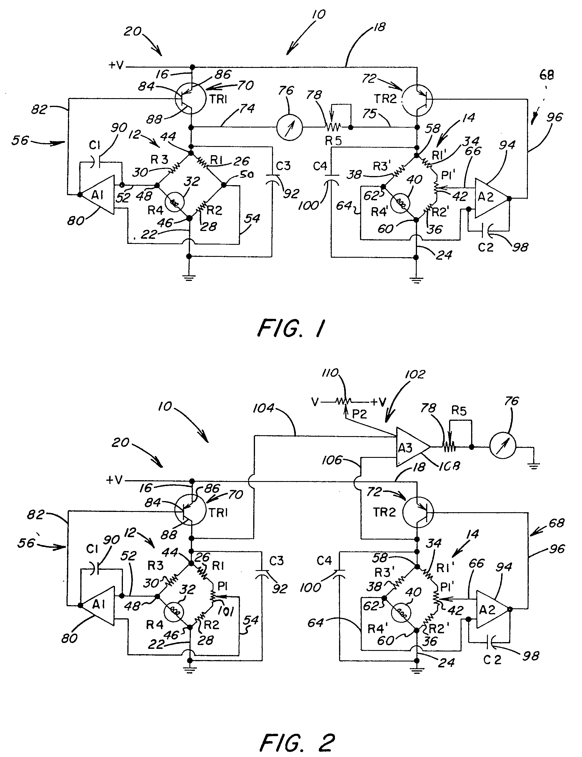
[0015] The invention will now be further described, by way of illustrative and non-limiting
example, with reference to the accompanying drawings, in which:
Figure 1 is an electrical schematic of apparatus for measuring the amount of combustibles
present in a gas, illustrating a pair of balanced bridge circuits with control means
for regulating voltages applied to the circuits; and
Figure 2 is an electrical schematic similar to Figure 1, illustrating apparatus for
operating a detector filament and a reference filament at different temperatures.
[0016] Referring to the drawings and particularly to Figure 1, there is illustrated a combustibles
detector circuit 10 that is operable to provide a quantitative measurement of the
amount of combustibles present in gaseous by-products of a combustion process. The
detector circuit 10 includes a pair of balanced bridge circuits 12 and 14. The circuit
12 is a detector or measuring bridge and the circuit 14 is a reference bridge. The
bridges 12 and 14 are connected by conductors 16 and 18 respectively to a DC voltage
source 20. The bridges 12 and 14 are also connected by conductors 22 and 24 respectively
to ground.
[0017] The detector bridge 12 includes resistors 26, 28, 30 and 32 arranged in a balanced
bridge circuit. Similarly, the reference bridge 14 includes resistors 34, 36, 38,
40 in addition to a variable resistor 42. The detector bridge 12 includes an input
terminal 44 connected to the voltage source 20, an output terminal 46 connected to
ground, and output terminals 48 and 50 connected by conductors 52 and 54 to a feedback
control circuit 56. The reference bridge 14 includes an input terminal 58 connected
to the voltage source 20, an output terminal 60 connected to ground, an output terminal
62, and also an output terminal provided by the variable resistor 42. The output terminal
62 and the variable resistor 42 are connected by conductors 64 and 66 respectively
to a feedback control circuit 68. The feedback control circuits 56 and 68 are connected
to the respective input terminals of the bridges 12and 14 by power switching devices
70 and 72. Preferably, the switching devices include transistors TR1 and TR2, as illustrated
in Figure 1. The output of the transistor TR1 is supplied by a conductor 74 to a readout
device 76. The output of the transistor TR2 is supplied by a conductor 75 through
a slide-wire potentiometer 78 to the readout device 76.
[0018] The resistor 32 of the detector bridge 12, which acts as a detector filament, and
the resistor 40 of the reference bridge 14, which acts as a reference filament, are
exposed to a flow stream of a gas to be measured for combustibles. Current passes
through both filaments 32 and 40, heating them to a temperature well below the ignition
temperature of the gas present. The detector filament 32 is coated with a catalyst
which causes the combustibles in the gas to burn on the surface of the filament 32
even at the low operating temperature of the filament. The reference filament 40 is
identical to the detector filament 42 except that it is not coated with a catalyst.
The resistance of the filaments 32 and 40 changes in response to changes of the ambient
temperature of the gas being measured, gas thermal conductivity, specific heat and
the electrical power applied to the filaments. In addition, the resistance and temperature
of the detector filament 32 increase when a gas containing combustibles is burned
on the surface of the filament 32.
[0019] The bridges 12 and 14 are initially balanced so that the output terminals 48 and
50 of the bridge 12 are at the same potential, and the output terminal 62 and the
terminal provided by the variable resistor 42 of the bridge 14 are at the same potential.
Adjustments in the output voltage of the bridge 14 for balancing the output voltage
with the output voltage of the bridge 12 are accomplished by the variable resistor
42. Thus, in the absence of a gas containing combustibles, the output voltages of
the detector and reference bridges 12 and 14 are equal. This is the balanced condition
of the bridges and is indicated by zero deflection of the readout device 76, which
is preferably a galvanometer. Accordingly, any variation which occurs in the output
voltage of the detector bridge 12 results in a deflection of the galvanometer 76 to
indicate the concentration of combustibles present in the gas. The slidewire potentiometer
78 provides a means for adjusting the galvanometer 76 so that the galvanometer will
read full scale for the respective gas being measured.
[0020] When the temperature of the detector filament 32 increases due to the combustion
of gas on its surface, the resistance of the filament 32 increases thereby unbalancing
the bridge circuit 12. Consequently, the outputs from the terminals 48 and 50 are
no longer equal. As stated above, the reference filament 40 does not react in this
manner because the filament is not coated with a catalyst; therefore, the reference
bridge 14 remains balanced. However, due to variations that may occur in the ambient
temperature of the gas being measured and the electrical power supplied to the reference
bridge 14, the output voltages from the terminal 62 and the variable resistor 42 may
vary. In order to compensate for the variation the feedback control circuit 68 and
the transistor 72 are automatically actuated to regulate the voltage supplied to the
bridge 14 to maintain the bridge in a balanced condition.
[0021] Under normal operating conditions the voltages at the output terminals 48 and 50
of the detector bridge 12 are equal, and a responsive signal is supplied to the feedback
control circuit 56. The control circuit 56 includes an operational amplifier 80 having
inputs connected to the conductors 52 and 54. The output of the operational amplifier
80 is connected by a conductor 82 to the base 84 of the transistor TR1 (70). The emitter
86 of the transistor 70 is connected by the conductor 16 to the voltage source 20,
and the transistor collector 88 is connected to the input terminal 44 of the detector
bridge 12.
[0022] Under balanced bridge conditions, the output terminals 48 and 50 of the detector
bridge 12 are at the same potential. The amplifier 80 is actuated to supply an output
signal of a preselected magnitude through the conductor 82 to the transistor base
84. The output signal of the amplifier 80 switches the transistor 70 to a conductive
state to permit current flow from the source 20 to the detector bridge input terminal
44. The voltage that is applied to the terminal 44 is a regulated voltage that maintains
the bridge circuit 12 in a balanced condition when a gas free of combustibles is exposed
to the detector filament 32. The voltage applied to the bridge 12 will vary from the
present regulated voltage when a gas containing combustibles is exposed to the detector
filament 32. (As mentioned above, the catalyst on the detector filament 32 promotes
ignition of the combustibles in the gas even at the low operating temperature of the
filament 32.)
[0023] Burning of the combustibles increases the temperature of the detector filament 32
to, in turn, increase the resistance of the filament 32. The voltages at the output
terminals 48 and 50 are no longer equal, creating an unbalanced bridge condition.
Consequently, the input signals to the operational amplifier 80 from the output terminals
48 and 50 are no longer equal. The amplifier 80 is actuated to operate at a reduced
output so that the magnitude of the input signal to the transistor base 84 is lowered,
thereby switching the transistor 70 from a conductive state to a non-conductive state.
The collector current is interrupted, and the voltage applied to the detector bridge
12 is reduced.
[0024] Reducing the detector bridge voltage reduces the temperature of the detector filament
32 to a point where the detector bridge 12 is again balanced. The amplifier 80 is
restored to operation at an increased output level, and the transistor 70 is switched
to a conductive state. The voltage of the detector bridge 12 is then increased to
a magnitude to maintain the bridge in a balanced condition and the temperature of
the detector filament 32 constant. Thus, by switching the transistor 70 between a
conductive and a non-conductive state in response to the operating level of the amplifier
80, the voltage applied to the detector bridge 12 is continually being adjusted to
maintain a balanced bridge condition.
[0025] The adjustment in the voltage applied to the detector bridge 12 is an indication
of the combustibles concentration. The voltage differential is recorded by the galvanometer
76 and is indicated by a meter deflection from an initial zero reading. The meter
deflection supplies a quantitative readout of the concentration of combustibles present
in the gas being measured. Accordingly, the combustibles concentration is proportional
to the adjustment in the voltage between the transistors 70 and 72. Thus, the voltage
applied to the detector bridge 12 to maintain the bridge balanced is used as a measurement
of the combustibles concentration, unlike conventionally known catalytic detectors
in which the voltage unbalance serves as a measurement of the combustibles concentration.
By maintaining the detector bridge in a balanced condition, the detector filament
32 is maintained at a constant temperature to increase the operating life of the filament
32.
[0026] As illustrated in Figure 1, a capacitor 90 is connected to the conductor 52 at the
input to the amplifier 80 and to the output of the amplifier 80. The function of the
capacitor 90 is to dampen or slow down the operation of the amplifier 80 between a
high output state and a low output state. With this arrangement the switching of the
transistor 70 between a conductive state and a non-conductive state is slowed down
to reduce ripple effect at the output of the transistor 70 to the galvanometer 76.
This provides a more uniform readout of the galvanometer.
[0027] As the operational amplifier 80 fluctuates between a high output state and a low
output state, the transistor 70 switches on and off. Preferably, the rate of transition
between these two states is delayed sufficiently by the capacitor 90 to provide an
average reading of the combustibles concentration on the galvanometer 76. To further
prevent an undesirably rapid deflection of the galvanometer 76, an additional storage
capacitor 92 may be positioned across the bridge input terminal 44 and the connection
of the output terminal 46 to ground. When the transistor 70 is in a conductive state
the capacitor 92 stores voltage. The stored voltage is released by the capacitor 92
over a predetermined interval to the detector bridge 12 when the transistor 70 is
in a non-conductive state. The voltage supplied to the bridge 12 through the capacitor
92 is also supplied to the galvanometer 76. A rapid transition in the applied voltage
due to combustion of the gas on the filament 32 is averaged out by the operation of
the capacitor 92 so that a uniformly changing readout, as opposed to a rapidly changing
readout, is indicated by the galvanometer 76. In this manner, the performance of the
galvanometer is substantially improved.
[0028] During the non-conductive cycle of operation of the transistor 70, the temperature
of the detector filament 32 decreases. When the temperature of the filament 32 decreases
to a level below its initial operating temperature, at which there is no combustion
on its surface, the amplifier 80 is switched to a high output state. This returns
the transistor 70 to a conductive state. The voltage of the capacitor 92 is increased
to a magnitude that once again balances the bridge 12. Thus, the transistor 70 continues
to turn on and off to maintain the capacitor 92 at a voltage level which balances
the bridge 12. By maintaining the bridge balanced, the temperature of the filament
32 remains constant. Accordingly, the variation in the voltage applied to the bridge
12 to maintain a balanced bridge condition is an indication of the combustibles concentration
in the gas being measured.
[0029] The reference detector 14 is provided with a feedback control circuit 68 which is
similar in construction to the feedback control circuit 56 of the detector bridge
12. The feedback control circuit 68 includes an operational amplifier 94 arranged
to receive outputs from the variable resistor 42 and from the bridge output terminal
62. The amplifier 94 is connected by a conductor 96 to the power switching device
72 (transistor TR2). Also, the feedback control circuit 68 includes a capacitor 98
positioned across the input to the amplifier 94 from the output terminal 62 and the
output of the amplifier 94 to the transistor 72. A storage capacitor 100, similar
to the storage capacitor 92 in the bridge 14, is positioned across the output of the
transistor 72 to the input terminal 58 and the output terminal 60 to ground.
[0030] For the reference bridge 14, the resistance of the reference filament 40 changes
in response to the ambient temperature of the gas being measured and the voltage applied
to the filament 40. A change in either of these factors will unbalance the reference
bridge 14 and actuate the amplifier 94 to switch from a high output state to a low
output state. Consequently, the transistor 72 becomes non-conductive and the voltage
applied to the bridge 14 is adjusted to restore the bridge to a balanced voltage condition
at which the temperature of the reference filament 40 remains at a preselected level.
Thus, the power supplied to the reference bridge 14 is adjusted by the feedback control
circuit 68 to maintain the bridge balanced. As stated above, the reference filament
40 is not sensitive to the presence of combustibles in the gas.
[0031] Referring to Figure 2, there is illustrated another embodiment of the present invention
which is similar to that shown in Figure 1 but which includes means for initially
setting the filaments 32 and 40 at different temperatures. This is desirable in a
combustibles detector circuit for which the resistances of the detector filament 32
and the reference filament 40 are unequal, and the respective bridges operate at different
initial voltages. Thus, the detector filament 32 may be maintained at a lower temperature
in a balanced bridge condition than the reference filament 40. Also, if one of the
two bridges is more temperature sensitive, the more sensitive bridge can be initially
calibrated to operate in a balanced condition at a lower current level.
[0032] Given the optimum temperature for operating the respective filaments, the initial
voltage to be applied to the respective filaments to maintain the filaments at this
temperature is predetermined. As illustrated in Figure 2, the detector bridge 12 is
provided with a variable resistor 101 similar to the variable resistor 42 of the reference
bridge 14. The variable resistors 42 and 101 are set so that the desired voltage is
applied to the filaments 32 and 40. In view of the fact that the filaments 32 and
40 operate at different temperatures, the output voltages from the bridges 12 and
14 will not be equal. Accordingly, the output voltages from the transistors 70 and
72 will not be equal, and the galvanometer 76 must be adjusted so that the initial
reading is zero for a gas having no combustibles.
[0033] The calibration of the galvanometer 76 when varying voltages are applied in a balanced
state to the transistors 70 and 72 is accomplished by a voltage adjustment circuit
102. The circuit 102 includes a pair of input conductors 104 and 106 connected to
the output terminals (collectors) of the transistors 70 and 72 respectively. The conductors
104 and 106 are connected to inputs of an operational amplifier 108. The inputs from
the transistors 70 and 72 actuate the amplifier 108 to generate a corresponding output
through the slidewire potentiometer 78 to the galvanometer 76.
[0034] In view of the fact that the input signals to the operational amplifier 108 from
the transistors 70 and 72 are different from the initial calibrated condition of a
gas free of combustibles, the input signals must be adjusted so that there is no deflection
of the galvanometer 76. For the embodiment illustrated in Figure 2 in which the detector
filament 32 is operating at a lower temperature than the reference filament 40, the
output voltage of the transistor 70 is lower than the output voltage of the transistor
72. Thus, a variable resistor 110 is connected to the summing junction of the conductor
104 to the amplifier 108. The variable resistor 110 is set to balance the input signal
from the transistor 70 with the input signal from the transistor 72. This provides
an initial zero reading of the galvanometer 76 for operation of the filaments 32 and
40 at different temperatures.
[0035] Thus, the detector bridge 12 can be operated at a reduced voltage level, which serves
to extend the useful life of the detector filament 42. The detector filament 32 is
exposed to lower temperature increases so the filament will not burn out. Evaporation
of the catalyst on the surface of the detector filament 32 is substantially reduced
to prolong the useful life of the detector filament. Once the input signals to the
amplifier 108 are adjusted to initially calibrate the galvanometer 76, the operation
of the feedback control circuits 56 and 68 to regulate the voltages applied to the
bridges 12 and 14 illustrated in Figure 2 is identical to that described above for
operation of the circuit 10 illustrated in Figure 1.
1. A method of measuring the amount of combustibles present in a gas, comprising exposing
the gas to a catalytic filament type detector means (12) and a reference means (14)
including a non-catalytic filament, feeding supply currents to the detector means
(12) and to the reference means (14), independently controlling said supply currents
in such a manner that the filaments of both the detector means (12) and the reference
means (14) are kept at preselected temperatures, the control of the supply current
to the detector means (12) being effected by the output signal of the detector means,
and measuring the magnitude of the adjusted supply current to the detector means (12)
in comparison to a signal corresponding to the output signal of the reference means
(14) to indicate a quantitative measurement of the combustibles present in the gas,
characterised by the step of effecting the control of the supply current to the detector
means by feeding back the output signal from the detector means (12) to a switching
means (70) at the input of the detector means, which switching means, in the case
of a departure of the filament temperature from the preselected value, adjusts the
magnitude of the supply current to interrupting the supply current to the detector
means (12) for the period required for the filament of the detector means (12) to
adopt again the preselected temperature.
2. A method according to claim 1, which includes initially balancing the output signals
of the detector means (12) and the reference means (14) in response to the gas being
free of combustibles.
3. A method according to claim 1, which includes controlling the rate of adjusting
the magnitude of the supply current to the detector means (12).
4. A method according to claim 1, which includes switching the switching means (70)
between a conductive state and a non-conductive state in response to the magnitude
of the feedback signal received from the output of the detector means (12).
5. A method according to claim 1, which includes measuring the supply current representative
of the concentration of combustibles in the gas in terms of the adjustment to the
voltage applied to the detector means (12) for maintaining the detector filament (32)
at the preselected temperature.
6. A method according to any one of claims 1 to 5, which includes feeding back an
output signal from the reference means (14) to a further switching means (72) at the
input of the reference means, adjusting the magnitude of the supply current to the
reference means (14) in response to the magnitude of the output signal of said reference
means by switching the further switching means (72) between a conductive state and
a non-conductive state, and maintaining the voltage applied to the reference means
(14) at a level resulting in the preselected temperature of the filament of the reference
means by switching of the switching means (72) to increase or decrease the magnitude
of the supply current supplied to the reference means (14).
7. A method according to claim 1, which includes actuating the switch means (70) between
a conductive state and a non-conductive state to adjust the voltage applied to the
detector means (12), which voltage maintains the catalytic detector filament (32)
of the detector means (12) at its preselected temperature, and recording the variation
in the voltage applied to the detector means when the switching means (70) is actuated
for maintaining the detector filament (32) at the preselected temperature to thereby
provide a quantitative electrical measurement of the concentration of the combustibles
present in the gas.
8. A method according to claim 1, which includes actuating an amplifier means (80)
in response to a change in the magnitude of the output signal of the detector means
(12), generating a feedback signal by the amplifier means (80) to the switching means
(70), actuating the switching means (70) in response to the magnitude of the feedback
signal to regulate the voltage applied to the detector means (12) for maintaining
the filament of the detector means at its preselected temperature, and measuring the
supply current representative of the concentration of combustibles present in the
gas in terms of the voltage applied to the detector means (12) for maintaining the
preselected temperature.
9. A method according to any one of claims 1 to 8, which includes operating the filament
of the detector means (12) at a first preselected temperature, operating the reference
means (14) at a second preselected temperature, and adjusting the output signal of
a selected one of the detector means (12) and the reference means (14) so that under
conditions for a gas free of combustibles the respective output signals are equal
to provide a readout indicating zero combustibles in the gas.
10. Apparatus for measuring the amount of combustibles present in a gas, comprising
a catalytic filament type detector means (12) arranged for exposure to the gas, the
detector means (12) having an input terminal (44) for receiving a supply current and
an output terminal (48, 50) for supplying an output signal, reference means (14) comprising
a non-catalytic filament and being arranged for exposure to the gas, a power source
(20) for feeding supply currents to the detector means (12) and the reference means
(14), feedback means (56, 68) for controlling said supply currents in such a manner
that the filaments are kept at preselected temperatures, said feedback means comprising
a feedback circuit (56) connected between the output terminal (48, 50) of the detector
means (12) and the input terminal (44) of the detector means, and meter means (76)
connected to the detector means (12) and the reference means (14) for recording the
difference in magnitude between the supply current to the detector means (12) and
a signal corresponding to the output signal of the reference means (14) as a quantitative
measurement of the amount of combustibles present in the gas, characterised in that
the feedback circuit (56) includes a power switching means (70) for controlling the
level of the supply current to the detector means (12), which power switching means,
in the case of a departure of the filament temperature from its preselected value,
adjusts the magnitude of the supply current by interrupting the supply current to
the detector means input terminal (44) for the period required for the filament of
the detector means to adopt again the preselected temperature.
11. Apparatus according to claim 10, which includes amplifier means (80) connected
to the output terminal (48) of the detector means (12) for receiving the output signal
of the detector means, the amplifier means (80) being operable in response to the
output signal of the detector means (12) to actuate the power switching means (70)
between a conductive state and a non-conductive state to thereby adjust the voltage
supplied to the detector means (12) to maintain the detector means at a preselected
voltage level.
12. Apparatus according to claim 10 or claim 11, which includes voltage storage means
(92) associated with the power switching means (70) for controlling the rate of change
in the voltage supplied to the detector means input terminal (44) from the power switching
means (70).
13. Apparatus according to claim 10, claim 11, or claim 12, wherein the meter means
(76) is arranged to receive the adjusted supply current of the detector means, the
meter means (76) is arranged to receive the signal corresponding to the output signal
of the reference means (14), said adjusted supply current and said signal being equal
in magnitude for a gas free of combustibles, and a voltage adjustment means (102)
is arranged to receive and adjust a selected one of said adjusted supply current and
said signal to a magnitude corresponding to the other to provide the meter means (76)
with an initial zero reading for a gas free of combustibles.
14. Apparatus according to claim 10, which includes an amplifier (80) positioned in
the feedback circuit (56), the amplifier being arranged to receive the output signal
of the detector means (12) and to generate a corresponding feedback signal to the
power switching means (70), the feedback signal from the amplifier (80) being proportional
to the concentration of the combustibles in the gas and operable to actuate the power
switching means (70) between a conductive state and a non-conductive state and thereby
adjust the supply current to the detector means (12) for maintaining the detector
means at a preselected voltage level.
15. Apparatus according to any one of claims 10 to 14, in which the detector means
(12) includes a balanced bridge circuit in which the detector filament (32) is arranged
to be exposed to the gas being measured, the detector filament (32) being coated with
a catalytic material, the reference means (14) includes a balanced bridge circuit
in which the reference filament (40) is arranged to be exposed to the gas being measured,
the power switching means (70) is arranged to adjust the level of the supply current
applied to the detector filament (32) to maintain the detector filament at a preselected
temperature, and the meter means (76) is arranged to receive the adjusted supply current
from the power switching means (70) and the signal corresponding to the output signal
of the reference means (14) and provide a quantitative readout of the adjusted supply
current required to maintain the detector filament (32) at its preselected temperature.
16. Apparatus according to claim 10, in which the power switching means (70) includes
a transistor (TR1) operable between a conductive state and a non-conductive state
to adjust the supply current applied to the detector means (12) to maintain the supply
current at a preselected level.
17. Apparatus according to any one of claims 10 to 16, which includes a further feedback
circuit (68) connected between an output terminal and an input terminal of the reference
means (14), the further feedback circuit (68) including a further power switching
means (72) for regulating the supply current applied to the reference means (14) to
maintain the reference means at its preselected temperature.
18. Apparatus according to claim 13, wherein the detector means (12) and the reference
means (14) can be arranged to operate at voltages of unequal magnitude, the detector
means (12) and the reference means (14) being operable to generate output signals
of unequal magnitude, and the voltage adjustment means (102) is provided for adjusting
a selected one of said output signals so that said output signals are of equal magnitude
to provide the meter means (76) with an initial signal indicating the absence of combustibles
in the gas being measured.
1. Verfahren zum Messen der Menge in einem Gas vorhandener brennbarer Bestandteile,
bei welchem das Gas einer katalytischen Phasendetektoreinrichtung (12) und einer Bezugseinrichtung
(14) mit einem nichtkatalytischen Faden ausgesetzt wird, Speiseströme der Detektoreinrichtung
(12) und der Bezugseinrichtung (14) zugeführt werden, die Speiseströme unabhängig
in der Weise gesteuert werden, daß die Fäden sowohl der Detektoreinrichtung (12) als
auch der Bezugseinrichtung (14) bei vorgewählten Temperaturen gehalten werden, wobei
die Steuerung des Speisestroms zu der Detektoreinrichtung (12) durch das Ausgangssignal
der Detektoreinrichtung erfolgt, und bei welchem man die Größe des eingestellten Speisestromes
zu der Detektoreinrichtung (12) in Vergleich zu einem Signal mißt, welches dem Ausgangssignal
der Bezugseinrichtung (14) entspricht, um eine quantitative Messung der in dem Gas
vorhandenen brennbaren Bestandteile anzuzeigen, dadurch gekennzeichnet, daß die Steuerung
des Speisestroms zu der Detektoreinrichtung durch Rückkopplung des Ausgangssignals
aus der Detektoreinrichtung (12) zu einer Schalteinrichtung (70) am Eingang der Detektoreinrichtung
erfolgt und die Schalteinrichtung in dem Fall, bei welchem die Fadentemperatur den
vorgewählten Wert verläßt, die Größe des Speisestromes dadurch einstellt, daß der
Speisestrom zu der Detektoreinrichtung (12) eine zeitlang unterbrochen wird, die für
den Faden der Detektoreinrichtung (12) ausreicht, um wieder die vorgewählte Temperatur
anzunehmen.
2. Verfahren nach Anspruch 1, dadurch gekennzeichnet, daß die Ausgangssignale der
Detektoreinrichtung (12) und der Bezugseinrichtung (14) in Abhängigkeit von dem an
brennbaren Bestandteilen freien Gas anfänglich abgeglichen werden.
3. Verfahren nach Anspruch 1, dadurch gekennzeichnet, daß die Geschwindigkeit der
Einstellung der Speisestromstärke zur Detektoreinrichtung (12) gesteuert wird.
4. Verfahren nach Anspruch 1, dadurch gekennzeichnet, daß die Schalteinrichtung (70)
zwischen einem leitenden Zustand und einem nichtleitenden Zustand geschaltet wird
in Abhängigkeit von der Größe des Rückkopplungssignals, welches von dem Ausgang der
Detektoreinrichtung (12) empfangen wird.
5. Verfahren nach Anspruch 1, dadurch gekennzeichnet, daß der Speisestrom gemessen
wird, welcher für die Konzentration der brennbaren Bestandteile in dem Gas repräsentativ
ist, als Justierung bzw. Anpassung an die an die Detektoreinrichtung (12) angelegte
Spannung, um den Detektorfaden (32) auf der vorgewählten Temperatur zu halten.
6. Verfahren nach einem der Ansprüche 1 bis 5, dadurch gekennzeichnet, daß ein Ausgangssignal
aus der Bezugseinrichtung (14) zu einer weiteren Schalteinrichtung (72) am Eingang
der Bezugseinrichtung rückgekoppelt wird, die Speisestromstärke der Bezugseinrichtung
(14) in Abhängigkeit zur Größe des Ausgangssignals der Bezugseinrichtung dadurch eingestellt
bzw. geregelt wird, daß die weitere Schalteinrichtung (72) zwischen einem leitenden
Zustand und einem nichtleitenden Zustand geschaltet wird, und daß die an die Bezugseinrichtung
(14) angelegte Spannung auf einem Niveau gehalten wird, welches zu der vorgewählten
Temperatur des Fadens der Bezugseinrichtung dadurch führt, daß die Schalteinrichtung
(72) zur Erhöhung oder Erniedrigung der Speisestromstärke geschaltet wird, welcher
der Bezugseinrichtung (14) zugeführt wird.
7. Verfahren nach Anspruch 1, dadurch gekennzeichnet, daß die Schalteinrichtung (70)
zwischen einem leitenden Zustand und einem nichtleitenden Zustand betätigt bzw. gesteuert
wird, um die Spannung einzuregeln, die an die Detektoreinrichtung (12) angelegt ist,
wobei die Spannung den katalytischen Detektorfaden (32) der Detektoreinrichtung (12)
auf seiner vorgewählten Temperatur hält, und daß die Veränderung der Spannung, welche
an die Detektoreinrichtung angelegt ist, aufgezeichnet wird, wenn die Schalteinrichtung
(70) zum Halten des Detektorfadens (32) an der vorgewählten Temperatur gesteuert wird,
um dadurch eine quantitative elektrische Messung der Konzentration der brennbaren
Bestandteile vorzusehen, die in dem Gas vorhanden sind.
8. Verfahren nach Anspruch 1, dadurch gekennzeichnet, daß eine Verstärkungseinrichtung
(80) in Abhängigkeit von einer Veränderung der Größe des Ausgangssignals der Detektoreinrichtung
(12) gesteuert wird, ein Rückkopplungssignal durch die Verstärkungseinrichtung (80)
zu der Schalteinrichtung (70) erzeugt wird, die Schalteinrichtung (70) in Abhängigkeit
von der Größe des Rückkopplungssignals betätigt bzw. gesteuert wird, um die Spannung
zu regulieren, die an der Detektoreinrichtung (12) angelegt ist, um den Faden der
Detektoreinrichtung auf seiner vorgewählten Temperatur zu halten, und daß der Speisestrom
gemessen wird, der für die Konzentration der brennbaren Bestandteile repräsentativ
ist, die sich in dem Gas befinden, un zwar als die Spannung, die an die Detektoreinrichtung
(12) angelegt ist, um die vorgewählte Temperatur zu halten.
9. Verfahren nach einem der Ansprüche 1 bis 8, dadurch gekennzeichnet, daß der Faden
der Detektoreinrichtung (12) bei einer ersten vorgewählten Temperatur betrieben wird,
die Bezugseinrichtung (14) bei einer zweiten vorgewählten Temperatur betrieben wird
und das Ausgangssignal einer ausgewählten Einrichtung der Detektoreinrichtungen (12)
und der Bezugseinrichtung (14) so eingestellt wird, daß unter Bedingungen für ein
Gas, welches frei an brennbaren Bestandteilen ist, die entsprechenden Ausgangssignale
gleich sind, um eine Ablesung vorzusehen, welche anzeigt, daß keine brennbaren Bestandteile
in dem Gas vorhanden sind.
10. Vorrichtung zum Messen der Menge in einem Gas vorhandener brennbarer Bestandteile
mit einer Detektoreinrichtung (12) mit katalytischem Faden, die so angeordnet ist,
daß sie dem Gas ausgesetzt ist, wobei sie einen Eingangsanschluß (44) aufweist zur
Aufnahme eines Speisestromes und einen Ausgangsanschluß (48, 50) für die Zufuhr eines
Ausgangssignals, Bezugseinrichtungen (14) aufweist mit einem nichtkatalytischen Faden,
die so angeordnet ist, daß sie dem Gas ausgesetzt ist, eine Energiequelle (20) aufweist
für das Zuführen von Speiseströmen zu der Detektoreinrichtung (12) sowie der Bezugseinrichtung
(14), Rückkopplungseinrichtungen (56, 68) aufweist für die Steuerung der Speiseströme
derart, daß die Fäden auf vorgewählten Temperaturen gehalten werden, wobei die Rückkopplungseinrichtung
eine Rückkopplungsschaltung (56) aufweist, die zwischen dem Ausgangsanschluß (48,
50) der Detektoreinrichtung (12) und dem Eingangsanschluß (44) der Detektoreinrichtung
verbunden ist, und Meßeinrichtungen (76) aufweist, die mit der Detektoreinrichtung
(12) und der Bezugseinrichtung (14) verbunden sind zur Aufzeichnung der Differenz
der Größe zwischen dem Speisestrom zur Detektoreinrichtung (12) und einem Signal,
welches dem Ausgangssignal der Bezugseinrichtung (14) entspricht, als eine quantitative
Messung der Menge von in dem Gas vorhandener brennbarer Bestandteile, dadurch gekennzeichnet,
daß die Rückkopplungsschaltung (56) eine Kraftschaltungseinrichtung (70) aufweist
für die Steuerung des Niveaus des Speisestromes zu der Detektoreinrichtung (12), und
daß die Kraftschaltungseinrichtung in dem Fall, daß die Fadentemperatur ihren vorgewählten
Wert verläßt, die Größe des Speisestromes dadurch einstellt, daß der Speisestrom zum
Eingangsanschluß (44) der Detektoreinrichtung eine zeitlang unterbrochen wird, die
ausreicht, daß der Faden der Detektoreinrichtung wieder die vorgewählte Temperatur
einnimmt.
11. Vorrichtung nach Anspruch 10, dadurch gekennzeichnet, daß eine Verstärkungseinrichtung
(80) mit dem Ausgangsanschluß (48) der Detektoreinrichtung (12) verbunden ist für
die Aufnahme des Ausgangssignals der Detektoreinrichtung und daß die Verstärkungseinrichtung
(80) in Abhängigkeit von dem Ausgangssignal der Detektoreinrichtung (12) betreibbar
ist, um die Kraftschaltungseinrichtung (70) zwischen einem leitenden Zustand und einem
nichtleitenden Zustand zu betätigen, um hierdurch die Spannung einzustellen, welche
der Detektoreinrichtung (12) zugeführt wird, um die Detektoreinrichtung auf einem
vorbestimmten Spannungsniveau zu halten.
12. Vorrichtung nach Anspruch 10 oder 11, dadurch gekennzeichnet, daß sie eine Spannungsspeichereinrichtung
(92) aufweist, welche der Kraftschaltungseinrichtung (70) zugeordnet ist zum Steuern
der Geschwindigkeit der Änderung der Spannung, welche dem Eingangsanschluß (44) der
Detektoreinrichtung von der Kraftschaltungseinrichtung (70) zugeführt wird.
13. Vorrichtung nach Anspruch 10, 11 oder 12, dadurch gekennzeichnet, daß die Meßeinrichtung
(76) derart angeordnet ist, daß sie den eingestellten Speisestrom der Detektoreinrichtung
aufnimmt, die Meßeinrichtung (76) derart angeordnet ist, daß sie das Signal aufnimmt,
welches dem Ausgangssignal der Bezugseinrichtung (14) entspricht, wobei der eingestellte
Speisestrom und das Signal für ein an brennbaren Bestandteilen freies Gas gleiche
Größe haben, und eine Spannungseinstelleinrichtung (102) angeordnet ist, um einen
ausgewählten eingestellten Speisestrom und das Signal aufzunehmen und einzurichten
auf eine Größe, welche der jeweils anderen Größe entspricht, um die Meßeinrichtung
(76) mit einer anfänglichen Nullablesung für ein an brennbaren Bestandteilen freies
Gas zu versehen.
14. Vorrichtung nach Anspruch 10, dadurch gekennzeichnet, daß sie einen Verstärker
(80) aufweist, der in der Rückkopplungsschaltung (56) sowie derart angeordnet ist,
daß er das Ausgangssignal der Detektoreinrichtung (12) aufnimmt und ein entsprechendes
Rückkopplungssignal zu der Kraftschaltungseinrichtung (70) erzeugt, und daß das Rückkopplungssignal
von dem Verstärker (80) proportional zu der Konzentration der brennbaren Bestandteile
in dem Gas ist und derart betreibbar ist, daß es die Kraftschaltungseinrichtung (70)
zwischen einem leitenden Zustand und einem nichtleitenden Zustand betätigt bzw. steuert
und dadurch den Speisestrom zu der Detektoreinrichtung (12) einstellt, um die Detektoreinrichtung
auf einem vorgewählten Spannungsniveau zu halten.
15. Vorrichtung nach einem der Ansprüche 10 bis 14, dadurch gekennzeichnet, daß die
Detektoreinrichtung (12) eine abgeglichene Brückenschaltung aufweist, in welcher der
Detektorfaden (32) so angeordnet ist, daß er dem in Messung befindlichen Gas ausgesetzt
ist, wobei der Detektorfaden (32) mit einem katalytischen Material beschichtet ist,
daß die Bezugseinrichtung (14) eine abgeglichene Brückenschaltung aufweist, in welcher
der Bezugsfaden (40) so angeordnet ist, daß er dem in Messung befindlichen Gas ausgesetzt
wird, daß die Kraftschaltungseinrichtung (70) derart angeordnet ist, daß sie das Niveau
bzw. die Größe des Speisestromes einstellt, der auf den Detektorfaden (32) aufgebracht
wird, um den Detektorfaden auf einer vorgewählten Temperatur zu halten, und daß die
Meßeinrichtung (76) derart angeordnet ist, daß sie den eingestellten Speisestrom aus
der Kraftschaltungseinrichtung (70) und das Signal aufnimmt, welches dem Ausgangssignal
der Bezugseinrichtung (14) entspricht und eine quantitative Ablesung des eingestellten
Speisestromes vorsieht, der erforderlich ist, um den Detektorfaden (32) auf seiner
vorgewählten Temperatur zu halten.
16. Vorrichtung nach Anspruch 10, dadurch gekennzeichnet, daß die Kraftschalteinrichtung
(70) einen Transistor (TR1) aufweist, der zwischen einem leitenden Zustand und einem
nichtleitenden Zustand betreibbar ist, um den Speisestrom einzustellen, der auf die
Detektoreinrichtung (12) aufgebracht wird, um den Speisestrom auf einem vorgewählten
Niveau zu halten.
17. Vorrichtung nach einem der Ansprüche 10 bis 16, dadurch gekennzeichnet, daß sie
eine weitere Rückkopplungsschaltung (68) aufweist, die zwischen einem Ausgangsanschluß
und einem Eingangsanschluß der Bezugseinrichtung (14) verbunden ist, wobei die weitere
Rückkopplungsschaltung (68) eine weitere Kraftschaltungseinrichtung (72) aufweist
für die Regulierung des Speisestromes der auf die Bezugseinrichtung (14) aufgebracht
wird, um die Bezugseinrichtung auf ihrer vorgewählten Temperatur zu halten.
18. Vorrichtung nach Anspruch 13, dadurch gekennzeichnet, daß die Detektoreinrichtung
(12) und die Bezugseinrichtung (14) derart angeordnet sein können, daß sie bei Spannungen
ungleicher Größe arbeiten, daß die Detektoreinrichtung (12) und die Bezugseinrichtung
(14) betreibbar sind, um Ausgangssignale ungleicher Größe zu erzeugen, und daß die
Spannungseinstelleinrichtung (102) für das Einstellen eines ausgewählten Signales
der Ausgangssignale derart vorgesehen ist, daß die Ausgangssignale gleicher Größe
haben, um eine Meßeinrichtung (76) vorzusehen mit einem anfänglichen Signal, welches
die Abwesenheit von in einem in Messung befindlichen Gas vorhandenen brennbaren Bestandteilen
anzeigt.
1. Un procédé de mesure de la quantité de constituants combustibles présents dans
un gaz, dans lequel on expose au gaz des moyens détecteurs (12) du type à filament
catalytique et des moyens de référence (14) comprenant un filament non catalytique,
on applique des courants d'alimentation aux moyens détecteurs (12) et aux moyens de
référence (14), on commande indépendamment ces courants d'alimentation d'une manière
telle que les filaments des moyens détecteurs (12) comme des moyens de référence (14)
soient maintenus à des températures présélectionnées, la commande du courant d'alimentation
appliqué aux moyens détecteurs (12) étant effectuée par le signal de sortie des moyens
détecteurs, et on mesure la valeur du courant d'alimentation réglé qui est appliqué
aux moyens détecteurs (12), par comparaison avec un signal correspondant au signal
de sortie des moyens de référence (14), pour donner une mesure quantitative des constituants
combustibles présents dans le gaz, caractérisé par l'opération consistant à effectuer
la commande du courant d'alimentation appliqué aux moyens détecteurs en renvoyant
le signal de sortie des moyens détecteurs (12) vers des moyens de commutation (70)
placés à l'entrée des moyens détecteurs et, dans le cas d'un écart de la température
du filament par rapport à la valeur présélectionnée, ces moyens de commutation règlent
la valeur du courant d'alimentation en interrompant le courant d'alimentation appliqué
aux moyens détecteurs (12) pendant la durée nécessaire pour que le filament des moyens
détecteurs (12) reprenne la température présélectionnée.
2. Un procédé selon la revendication 1, qui comprend l'équilibrage initial des signaux
de sortie des moyens détecteurs (12) et des moyens de référence (14), dans les conditions
dans lesquelles le gaz est exempt de constituants combustibles.
3. Un procédé selon la revendication 1, qui comprend la limitation de la vitesse de
réglage de la valeur du courant d'alimentation appliqué aux moyens détecteurs (12).
4. Un procédé selon la revendication 1, qui comprend la commutation des moyens de
commutation (70) entre un état conducteur et un état non conducteur sous la dépendance
de la valeur du signal de réaction reçu à partir de la sortie des moyens détecteurs
(12).
5. Un procédé selon la revendication 1, qui comprend la mesure du courant d'alimentation
représentatif de la concentration en constituants combustibles dans le gaz, exprimée
par le réglage de la tension appliquée aux moyens détecteurs (12) pour maintenir le
filament détecteur à la température présélectionnée.
6. Un procédé selon l'une quelconque des revendications 1 à 5, qui comprend le renvoi
d'un signal de sortie des moyens de référence (14) vers des moyens de commutation
supplémentaires (72) à l'entrée des moyens de référence, le réglage de la valeur du
courant d'alimentation appliquée aux moyens de référence (14) sous la dépendance de
la valeur du signal de sortie des moyens de référence, par commutation des moyens
de commutation supplémentaires (72) entre un état conducteur et un état non conducteur,
et le maintien de la tension appliquée aux moyens de référence (14) à un niveau qui
résulte de la température présélectionnée du filament des moyens de référence, par
commutation des moyens de commutation (72) pour augmenter ou diminuer la valeur du
courant d'alimentation appliqué aux moyens de référence (14).
7. Un procédé selon la revendication 1, qui comprend l'actionnement des moyens de
commutation (70) pour les faire commuter entre un état conducteur et un état non conducteur,
afin de régler la tension appliquée aux moyens détecteurs (12), cette tension maintenant
le filament détecteur catalytique (32) des moyens détecteurs (12) à sa température
présélectionnée, et l'enregistrement de la variation de la tension appliquée aux moyens
détecteurs lorsque les moyens de commutation (70) sont actionnés pour maintenir le
filament détecteur (32) à la température présélectionnée, pour donner ainsi une mesure
électrique quantitative de la concentration des constituants combustibles présents
dans le gaz.
8. Un procédé selon la revendication 1, qui comprend l'actionnement de moyens amplificateurs
(80) sous l'effet d'une variation de la valeur du signal de sortie des moyens détecteurs
(12), la génération d'un signal de réaction, appliqué aux moyens de commutation (70)
par ies moyens amplificateurs (80), l'actionnement des moyens de commutation (70)
sous la dépendance de la valeur du signal de réaction, pour réguler la tension appliquée
aux moyens détecteurs (12), afin de maintenir le filament des moyens détecteurs à
sa température présélectionnée, et la mesure du courant d'alimentation représentatif
de la concentration en constituants combustibles présents dans le gaz, exprimée par
la tension appliquée aux moyens détecteurs (12), pour maintenir la température présélectionnée.
9. Un procédé selon l'une quelconque des revendications 1 à 8, dans lequel on fait
fonctionner le filament des moyens détecteurs (12) à une première température présélectionnée,
on fait fonctionner les moyens de référence (14) à une seconde température présélectionnée,
et on règle le signal de sortie de moyens sélectionnés parmi les moyens détecteurs
(12) et les moyens de référence (14), de façon que dans des conditions correspondant
à un gaz exempt de constituants combustibles, les signaux de sortie respectifs soient
égaux, pour donner une indication représentant l'absence de constituants combustibles
dans le gaz.
10. Appareil pour la mesure de la quantité de constituants combustibles présents dans
un gaz, comprenant des moyens détecteurs (12) du type à filament catalytique, conçus
pour être exposés au gaz, les moyens détecteurs (12) ayant une borne d'entrée (44)
pour recevoir un courant d'alimentation et une borne de sortie (48, 50) pour fournir
un signal de sortie, des moyens de référence (14) comprenant un filament non catalytique
et étant conçus de façon à être exposés au gaz, une source d'énergie (20) destinée
à fournir des courants d'alimentation aux moyens détecteurs (12) et aux moyens de
référence (14), des moyens de réaction (56, 58) destinés à commander les courants
d'alimentation d'une manière telle que les filaments soient maintenus à des températures
présélectionnées, ces moyens de réaction comprenant un circuit de réaction (56) connecté
entre la borne de sortie (48, 50) des moyens détecteurs (12) et la borne d'entrée
(44) des moyens détecteurs, et des moyens de mesure (76) connectés aux moyens détecteurs
(12) et aux moyens de référence (14) pour enregistrer la différence de valeur entre
le courant d'alimentation appliqué aux moyens détecteurs (12) et un signal correspondant
au signal de sortie des moyens de référence (14), en tant que mesure quantitative
de la quantité de constituants combustibles présents dans le gaz, caractérisé en ce
que le circuit de réaction (56) comprend des moyens de commutation de puissance (70)
destinés à commander le niveau du courant d'alimentation appliqué aux moyens détecteurs
(12) et, dans le cas d'un écart de la température du filament par rapport à sa valeur
présélectionnée, ces moyens de commutation de puissance règlent la valeur du courant
d'alimentation en interrompant le courant d'alimentation appliqué à la borne d'entrée
des moyens détecteurs (44) pendant la durée nécessaire pour que le filament des moyens
détecteurs reprenne la température présélectionnée.
11. Appareil selon la revendication 10, comprenant des moyens amplificateurs (80)
connectés à la borne de sortie (48) des moyens détecteurs (12) pour recevoir le signal
de sortie des moyens détecteurs, les moyens amplificateurs (80) pouvant fonctionner
sous la dépendance du signal de sortie des moyens détecteurs (12) pour actionner les
moyens de commutation de puissance (70) de façon à les commuter entre un état conducteur
et un état non conducteur, pour régler ainsi la tension qui est appliquée aux moyens
détecteurs (12), afin de maintenir les moyens détecteur à un niveau de tension présélectionnée.
12, Appareil selon la revendication 10 ou la revendication 11, comprenant des moyens
de stockage de tension (92) associés aux moyens de commutation de puissance (70) pour
limiter la vitesse de variation de la tension appliquée à la borne d'entrée des moyens
détecteurs (44) à partir des moyens de commutation de puissance (70).
13. Appareil selon la revendication 10, la revendication 11 ou la revendication 12,
dans lequel les moyens de mesure (76) sont conçus de façon à recevoir le courant d'alimentation
réglé des moyens détecteurs, les moyens de mesure (76) sont conçus de façon à recevoir
le signal correspondant au signal de sortie des moyens de référence (14), le courant
d'alimentation réglé et ce signal ayant des valeurs égales pour un gaz exempt de constituants
combustibles, et des moyens de réglage de tension (102) sont conçus de façon à recevoir
et à régler un paramètre sélectionné entre le courant d'alimentation réglé et ledit
signal, pour lui donner une valeur correspondant à l'autre, de façon que les moyens
de mesure (76) indiquent initialement une valeur nulle pour un gaz exempt de constituants
combustibles.
14. Appareil selon la revendication 10, comprenant un amplificateur (80) positionné
dans le circuit de réaction (56), l'amplificateur étant conçu de façon à recevoir
le signal de sortie des moyens détecteurs (12) et à générer un signal de réaction
correspondant dirigé vers les moyens de commutation de puissance (70), le signal de
réaction provenant de l'amplificateur (80) étant proportionnel à la concentration
de constituants combustibles dans le gaz, et pouvant actionner les moyens de commutation
de puissance (70) pour les faire commuter entre un état conducteur et un état non
conducteur et régler ainsi le courant d'alimentation appliqué aux moyens détecteurs
(12), pour maintenir les moyens détecteurs à un niveau de tension présélectionné.
15. Appareil selon l'une quelconque des revendications 10 à 14, dans lequel les moyens
détecteurs (12) comprennent un circuit en pont équilibré dans lequel le filament détecteur
(32) est disposé de façon à être exposé au gaz qui est mesuré, le filament détecteur
(32) étant revêtu d'une matière catalytique, les moyens de référence (14) comprennent
un circuit en pont équilibré dans lequel le filament de référence (40) est disposé
de façon à être exposé au gaz qui est mesuré, les moyens de commutation de puissance
(70) sont conçus de façon à régler le niveau du courant d'alimentation appliqué au
filament détecteur (32) pour maintenir le filament détecteur à une température présélectionnée,
et les moyens de mesure (76) sont conçus de façon à recevoir le courant d'alimentation
réglé provenant des moyens de commutation de puissance (70) et le signal correspondant
au signal de sortie des moyens de référence (14), et de façon à fournir une indication
quantitative du courant d'alimentation réglé qui est nécessaire pour maintenir le
filament détecteur (32) à sa température présélectionnée.
16. Appareil selon la revendication 10, dans lequel les moyens de commutation de puissance
(70) comprennent un transistor (TR1) qu'on peut commuter entre un état conducteur
et un état non conducteur pour régler le courant d'alimentation appliqué aux moyens
détecteurs (12) afin de maintenir le courant d'alimentation à un niveau présélectionné.
17. Appareil selon l'une quelconque des revendications 10 à 16, comprenant un circuit
de réaction supplémentaire (68) connecté entre une borne de sortie et une borne d'entrée
des moyens de référence (14), le circuit de réaction supplémentaire (68) comprenant
des moyens de commutation de puissance supplémentaires (72) pour réguler le courant
d'alimentation appliqué aux moyens de référence (14) de façon à maintenir les moyens
de référence à leur température présélectionnée.
18. Appareil selon la revendication 13, dans lequel les moyens détecteurs (12) et
les moyens de référence (14) sont conçus de façon à pouvoir fonctionner à des tensions
de valeur inégale, les moyens détecteur (12) et les moyens de référence (14) pouvant
fonctionner de façon à générer des signaux de sortie de valeur inégale, et les moyens
de réglage de tension (102) sont destinés à régler l'un sélectionné des signaux de
sortie, de façon que ces signaux de sortie soient de valeur égale pour appliquer aux
moyens de mesure (76) un signal initial indiquant l'absence de constituants combustibles
dans le gaz qui est mesuré.