| (19) |
 |
|
(11) |
EP 0 114 058 A1 |
| (12) |
EUROPEAN PATENT APPLICATION |
| (43) |
Date of publication: |
|
25.07.1984 Bulletin 1984/30 |
| (22) |
Date of filing: 11.01.1984 |
|
|
| (84) |
Designated Contracting States: |
|
AT BE CH DE FR GB IT LI LU NL SE |
| (30) |
Priority: |
17.01.1983 NL 8300172
|
| (71) |
Applicant: Troost Pernis Groep B.V. |
|
NL-3201 LG Spijkenisse (NL) |
|
| (72) |
Inventor: |
|
- Koopman, Hendrik
NL-3297 TM Puttershoek (NL)
|
| (74) |
Representative: Hoijtink, Reinoud et al |
|
Arnold & Siedsma,
Advocaten en Octrooigemachtigden,
Sweelinckplein 1
2517 GK Den Haag
2517 GK Den Haag (NL) |
|
| |
|
| (54) |
Method for connecting pipes being provided with an inner protective cladding |
(57) Method for connecting pipes (1), (6), provided with an internal protective coating,
being sensible for heat. First on each of the pipes by the head end an annular coupling
element (2), (7) has been welded. Then the pipes are being provided with an internal
protective coating. Finally the annular coupling elements are welded to one another
at a relatively large distance from the pipes such that the welding heat is prevented
from reaching the protective coating.
|
|
[0001] The invention relates to a method of manufacturing and joining pipes provided with
an internal protective coating.
[0002] Such pipes provided with an anti-corrosion coating are particularly used in the chemical
and, more particularly, the petrochemical industry and, in general in the oil industry.
A condition for a satisfactorily operating pipeline is that the pipes should be effectively
protected against corrosion also at the seams of two pipes contacting by their head
ends. When joining pipes care should be taken not to damage the protective coating.
Such pipes have hitherto been interconnected inter alia by means of flanges. The flanges
are intercoupled by bolt-and nut joints. The inconvenience of such a joint is that
in order to avoid leakage stuffing material has to be sandwiched between the flanges,
which material should preferably also be provided with a protective layer. This is
difficult, expensive and not reliable. Moreover, the often circuitous jobs have to
be carried out in the field. Welding pipes to one another brings about a great risk
of burning or overheating of the coating, usually of synthetic resins, due to the
welding heat so thai the coating does no longer completely cover the pipe surface.
[0003] The invention has for its object to provide a solution for this problem. According
to the invention this is achieved by taking the steps defined in the claims.
[0004] The invention will be described more fully with reference to the accompanying drawings.
[0005] Figs. 1 to 6 illustrate the various stages in which the pipe parts to be interconnected
are made and welded to' one another in accordance with the method embodying the invention.
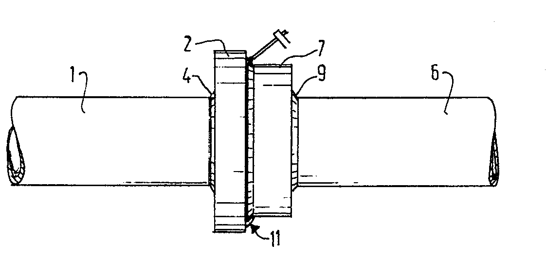
[0006] Referring to Fig. 1 the pipe 1 has slipped onto it an annular coupling element 2
so that a portion of length 3 of the pipe 1 protrudes out of the coupling element
2 subsequently by means of fillet welds 4 and 5 the coupling element 2 is sealed all
around on the pipe 1. As shown in Fig. 2 an annular coupling element 7 is slipped
onto a second pipe part 6 so that a portion 8 of the coupling element projects beyond
the pipe part 6. By welds 9 and 10 the coupling element 7 is sealed to the pipe part
6. Preferably the distance 8 by which the coupling element 7 extends beyond the pipe
part 6 is chosen to be equal to the distance 3 by which the pipe part 1 protrudes
out of the coupling element 2. Subsequently the two pipe parts are provided on the
inner side with a protective coating, for example, of synthetic resin by rotating
the parts and introducing the protective material.
[0007] Then the two pipe parts are brought into contact with one another by the head ends.
Before the pipe parts are contacted by the head ends, the head ends my be smeared
with layer of protective material (Fig. 4) in order to repair any damage, after which
the coupling elements (Fig. 5) are interconnected by means of fillet welds 11. It
should be noted that the diameter of one of the coupling elements, for example, the
coupling element 2, is chosen to be larger than that of the other coupling element
7. It is thus possible to interconnect the coupling elements by means of a fillet
weld 11.
[0008] Since the two coupling elements are welded to the associated pipe parts prior to
the application of the protective coating there is no risk of burning or overheating
of the protective coating due to the welding heat. Since the coupling elements are
welded to one another at a relatively large distance from the pipes and the protective
coating therein and since the thermal capacity of the coupling elements is relatively
high, the welding heat is prevented from reaching the protective coating to a significant
extent and from causing the coating to flow and hence to deteriorate. The diameters
of the coupling elements may be so large that it can be ensured that the welding heat
will not attain the protective coating. In the method embodying the invention the
sole work to be done in the field is welding the coupling elements. Since the pipe
parts to be joined with the associated coupling elements and the protective coating
are made in the factory the quality check is appreciably simplified and can be more
readily carried out than in the case of welding the coupling elements to the pipe
parts in the field.
[0009] Figure 6 shows an embodiment in which the diameters of the coupling elements are
equal to one another and in wnich a V weld 12 is made between the annular coupling
elements.
1. A method of manufacturing and joining pipes (1,6) provided with an internal protective
coating characterized in that one of the pipes (6) has welded to it an annular coupling
element (7) partly extending beyond the head of the pipe (6, 4, 5), the pipe (6) is
provided on the inner side with the protective coating, the other pipe (1) has welded
to it an annular coupling element (2) welds (9, 10) so that the head end of the pipe
(1) protrudes out of the coupling element (2), the pipe (1) is provided on the inner
side with a protective coating, the pipes (1, 6) are brought into contact with one
another by the. head ends and the coupling elements are welded to one another at a
distance from the pipes.
2. A method as claimed in claim 1 characterized in that a layer of protective material
is applied to the head ends (1, 6) of the pipes prior to bringing them into contact
with one another.
3. A method as claimed in claims 1 and 2 characterized in that the distance (8) by
which the coupling element extends beyond the first pipe (6) is equal to the distance
(3) by which the second pipe (1) protrudes out of the coupling element element (2)
arranged thereon.
4. A method as claimed in claims 1 to 3
characterized in that the diameter of one (2) of the coupling elements is chosen to
be larger than that of the other coupling element (7).
5. A method as claimed in claim 4
characterized in that the coupling elements (2, 7) are interconnected by a fillet
weld (11).
