| (19) |
 |
|
(11) |
EP 0 071 117 B1 |
| (12) |
EUROPEAN PATENT SPECIFICATION |
| (45) |
Mention of the grant of the patent: |
|
14.05.1986 Bulletin 1986/20 |
| (22) |
Date of filing: 16.07.1982 |
|
| (51) |
International Patent Classification (IPC)4: B63G 8/42 |
|
| (54) |
Underwater tow system and method
Unterwasserschleppvorrichtung und Verfahren
Méthode et dispositif de touage sous-marin
|
| (84) |
Designated Contracting States: |
|
AT BE CH DE FR GB IT LI NL SE |
| (30) |
Priority: |
31.07.1981 US 288947
|
| (43) |
Date of publication of application: |
|
09.02.1983 Bulletin 1983/06 |
| (71) |
Applicant: EDO WESTERN CORPORATION |
|
Salt Lake City
Utah 84115 (US) |
|
| (72) |
Inventors: |
|
- Lapetina, Robert Anthony
Salt Lake City
Utah 84117 (US)
- Brainard, II, Edward C.
Massachusetts 02738 (US)
|
| (74) |
Representative: Grünecker, Kinkeldey,
Stockmair & Schwanhäusser
Anwaltssozietät |
|
Maximilianstrasse 58
80538 München
80538 München (DE) |
|
| |
|
| Note: Within nine months from the publication of the mention of the grant of the European
patent, any person may give notice to the European Patent Office of opposition to
the European patent
granted. Notice of opposition shall be filed in a written reasoned statement. It shall
not be deemed to
have been filed until the opposition fee has been paid. (Art. 99(1) European Patent
Convention).
|
[0001] This invention relates to an underwater tow system and method according to the precharacterising
part of patent claims 1 and 21, respectively.
[0002] A tow system of the aforementioned kind is known from DE-B-1 045 860. In this reference,
an underwater sonic system is disclosed in which a submerged tow vehicle is connected
to a vessel travelling on the surface of the sea by a tow cable, the free end of which
is connected to a weight body contacting the seabed. An arm extending from the front
side of the tow vehicle and being rigidly secured thereto is pivotally connected to
a clamping means which, in turn, is connected to the tow cable at a predetermined
distance from the weight body. The tow vehicle has a neutral buoyancy in water so
that it is kept in a horizontal position under the influence of the movement of the
vessel towing the cable.
[0003] From FR-A-2 270 141, FR-A-2 274 501 and DE-C-334 689, systems for maintaining a self-
propelled, underwater travelling vessel at a predetermined distance to the seabed
are known. These systems comprise a tow rope being connected to the submarine vessel
and having a flexible end which contacts the seabed. By changing the length of the
cable being wound on a drum, the distance between the vessel and the seabed may be
influenced. The same principle for maintaining the distance to the ground is, for
instance, also used with airborne balloons in the landing stage.
[0004] In the first-mentioned underwater tow system, the tow vehicle may be influenced by
erratic movements of the vessel or cable due to the rather rigid connection of the
tow vehicle to the cable. It is, therefore, the object of the present invention to
provide an.underwater tow system in which the tow vehicle follows the ground closely
and is effectively immunised from erratic movements by the vessel or cable.
[0005] This object is solved by the characterising features of patent claim 1. Preferred
embodiments of the invention and a method for towing a vehicle underwater are the
subject matter of further claims.
[0006] The invention and its advantages and embodiments will become apparentfrom a consideration
of the following detailed description, presented in connection with the accompanying
drawings in which:
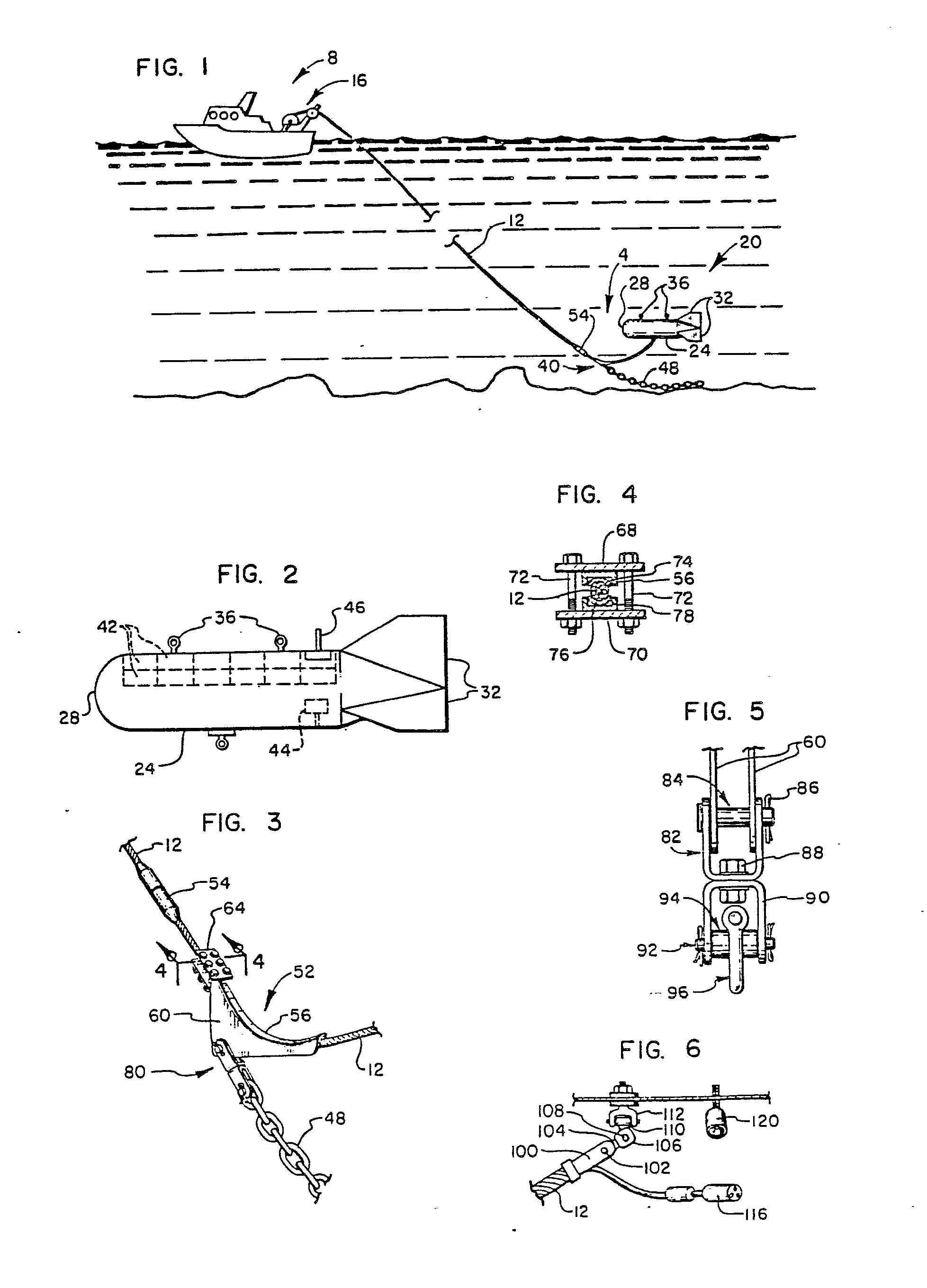
FIG. 1 is a side view of an underwater tow system made in accordance with the present
invention, showing the system as it could be utilised underwater;
FIG. 2 is a side elevation view of the tow vehicle of FIG. 1, showing the positioning
of some of the components in the vehicle;
FIG. 3 is a fragmented, perspective view of the fairlead assembly of the underwater
tow system of FIG. 1.
FIG. 4 is a cross-sectional view of the clamp of FIG. 3 taken along lines 4-4;
FIG. 5 is a front view of the coupling apparatus for coupling the chain of FIG. 3
to the fairlead assembly; and
FIG. 6 is a side view of the coupling apparatus for coupling the tow cable to the
tow vehicle.
Detailed Description
[0007] Referring to FIG. 1 there is shown an underwater tow system 4 made in accordance
with the present invention and being towed by a surface vessel 8. The tow system 4
is coupled by way of a tow cable 12 to a winch 16 on the vessel. The tow cable 12
includes, in a conventional manner, electrical conductors for connecting electrical
apparatus on board the ship 8 with underwater apparatus housed in a tow vehicle 20
of the underwater tow system.
[0008] The underwater tow system 4 includes the tow vehicle 20 (see FIGS. 1 and 2) formed
generally in the shape of a torpedo and having an elongate cylindrical body 24 rounded
on a front end 28 thereof. The rear of the body 24tapers inwardly to accommodate three
fins 32 circumferentially spaced about the body. The streamlined shape of the tow
body 24, together with the fins 32, serve to stabilize movement of the tow vehicle
through the water.
[0009] Eyelets 36 are attached to the top of the body 24 at spaced apart locations to provide
coupling or lifting elements by which the tow vehicle 20 may be lifted from the water.
[0010] Illustrative parameters of the tow vehicle 20 are a body length of about 17 feet,
a body diameter of 3 feet, and a weight of 1500 pounds in air (when component electrical
apparatus is included). The tow body 20 is constructed to be buoyant in water, with
a net buoyant force of about 250 pounds. Buoyancy is achieved by including within
the tow body 24 a plurality of syntactic foam cylinders, balls or blocks 42 positioned
against the inner wall of the body as shown in FIG. 2, and held in place, for example,
by epoxy. Of course, other buoyant material might also be utilized provided such material
did not interfere with operation of electrical equipment contained in the tow vehicle.
Syntactic foam has been found to be suitable since it does not resonate to thereby
create interference with acoustical equipment which might be utilized on the tow vehicle.
[0011] Also included in the tow vehicle is a conventional pinger 44 which is arranged to
automatically commence transmitting an acoustical signal when power to the pinger
is interrupted. This would occur if, for example, the tow vehicle were detached from
the tow cable. A light beacon 46 is positioned on top of the tow vehicle to emit light
if the tow vehicle floats to the surface. That is, the light beacon is attached to
emit light when the water pressure falls below some level indicating that the vehicle
is nearing the surface.
[0012] A fairlead assembly 40 interconnects the tow cable 12 with the tow vehicle 20 and
with a chain weight 48. The chain weight 48 includes a plurality of links, an end
one of which is coupled to the fairlead assembly 40. The chain weight is provided
to pull the tow vehicle 20 and tow cable 12 downwardly in the water until the chain
contacts the sea floor. As the ship 8 moves in the water, the chain weight 48 will
drag over the sea floor and, since the tow vehicle 20 is buoyant, the tow vehicle
will "fly" or move through the water at a substantially constant predetermined distance
above the sea floor. This distance depends upon the towing speed and the length of
the cable or coupling between the fairlead assembly 40 and the tow vehicle 20. For
a tow vehicle having a buoyant force of about 250 pounds, a weight for the chain 48
advantageously is about 2000 pounds. This weight, it has been found, is sufficient
to dampen small erratic movements by the tow cable 12 caused either by sea currents
or by small speed surges of the vessel 8. Because of this dampening effect, the tow
vehicle 20 remains more stable as it is pulled through the water. That is, the yaw,
heave and roll which might otherwise occur in the tow vehicle 20 by reason of erratic
movements of the tow cable 12 are reduced. Also, in the event that the ship 8 comes
to a halt, the tow vehicle 20, being buoyant, will continue to float above the sea
floor and not "crash" into the floor or other sea floor obstacle.
[0013] Although other types of weighting devices could be used, it has been found that the
use of a chain 48 is advantageous since the total weight can be readily modified by
simply removing or adding links. Also, slight variations in the speed of the ship
will generally result simply in a few more (or less) chain links contacting the sea
floor to still maintain the elevation of the tow vehicle 20 at a substantially constant
height above the sea floor. Thus there is not a single speed threshold level at which
the weight is lifted from the sea floor as might be the case with a unitary weight.
[0014] FIG. 3 shows a more detailed perspective view of the fairlead assembly 40 of FIG.
1. This assembly is swivelably coupled by an electromechanical coupler 54 to the cable
12. The coupler 54 is of conventional design. The assembly 40 includes a saddle 52
composed of a curved channel 56 into which the cable 12 is inserted, and a pair of
skirts 60 which extend downwardly on either side of the cable 12 as shown. An elongate
upper extension of the channel 56 and skirts 60 is placed in a clamp 64 for clamping
the fairlead assembly onto the cable 12. The cable 12 thus runs through the channel
56, between the skirts 60, and generally curves with the curvature of the channel.
[0015] The clamp is shown in greater detail in FIG. 4, which is a cross-sectional view thereof
taken along lines 4-4 of FIG. 3. As shown in FIG. 4, the clamp includes a top plate
68 and a bottom plate 70 held in a clamping relationship by bolts 72. The channel
56 of the fairlead assembly 52 which is held between the clamp includes a friction
pad 74. A channel element 78 is welded to the plate 70 and includes therein a similar
friction pad 76. These pads are shaped to fit snuggly about the tow cable 12 to hold
the tow cable in place when the clamp is tightened. Advantageously, the friction pads
74 and 76 are made of lead to deform against the cable as the clamp is tightened.
The pads are held in place in the channel 56 and the channel element 78 by pressure.
The side walls of the two channels 56 and 78 will mate to prevent damage to the cable
12 in the event the bolts 72 are tightened too tight.
[0016] Referring again to FIG. 3 and also to FIG. 5, it will be seen that the fairlead assembly
52 also includes a coupling mechanism 80 interconnecting the skirts 60 to the chain
weight 48. The coupling mechanism 80 includes a first clevis 82, the free ends of
which extends about the skirts 60 to align openings in the ends of the clevis with
openings in the skirt 60 through which a clevis pin 84 is inserted. A cotter pin 86
then secures the clevis pin 84 in place to thereby secure the clevis 82 on the skirts
60.
[0017] The base of the clevis 82 is swivelably attached by way of a bit 88 to the base of
a second clevis 90, as best seen in FIG. 5. A shear pin 92 extends through aligned
openings in the free ends of the clevis 90 and through a sleeve 94. A shackle 96 is
fitted in place about the sleeve 94 and this shackle is then linked with the end link
of the chain weight 48 to secure the chain weight onto the fairlead assembly. The
shear pin 92 is selected so as to break and release the shackle 96 from the clevis
90 when the shackle is subjected to some predetermined pulling force. Thus, if the
chain gets caught on the sea bottom, the shear pin 92 will release the chain to thus
avoid possible damage to the fairlead assembly which might otherwise occur if the
chain weight 48 were allowed to continue pulling on the assembly. The breaking strength
of the shear pin 92 must, of course, be greater than the weight of the chain 48 so
that while being launched in the water, the chain doesn't cause the shear pin to break.
For a chain weight of about 2000 pounds, the breaking strength of the shear pin 92
might illustratively be 4000 pounds.
[0018] FIG. 6 shows a side view of a connector mechanism by which the tow cable 12 is coupled
to the underneath side of the body 24 of the tow vehicle 20. This connecting apparatus
includes a gripping element 100 suitable for connection to the end of the tow cable
12. An exemplary gripping element might be the element known as Dyna-Grip produced
by Preformed Line Products Inc. of Cleveland, Ohio. The end of the gripping element
100, opposite the end at which the element is connected to the tow cable 12, is formed
into a clevis and includes a clevis pin 102 which is inserted in aligned openings
in the ends of the clevis to extend through the opening in a tongue 104 inserted in
the clevis. The tongue 104 is attached to a yoke 106 which includes aligned openings
through which a shear pin 108 extends. The shear pin 108 also extends through another
coupling element 110 which extends within a yoke 112 which is coupled to the underneath
side of the body 24 of the tow vehicle. The shear pin 108 has an illustratively breaking
strength of about 10,000 so that if the tow vehicle gets caught on some type of underwater
obstruction, the pin will break and release the tow vehicle to allow it to float to
the surface and be recovered. Upon release by the shear pin 108, electrical connectors
116 and 120 (such as the ER type waterproof connectors produced by Boston Insulated
Wire Co.) are pulled apart interrupting electrical power to the pinger 44 and this
causes the pinger (FIG. 2) to emit acoustical signals which may be detected on the
towing ship to indicate the location of the tow vehicle. In addition, the beacon light
46 begins emitting light signals as the vehicle reaches the water surface. The positioning
of the buoyant material 42 maintains the tow vehicle 20 upright on the surface so
that the beacon light 46 remains out of water. The connection between the tow vehicle
and the cable 12 allows pivoting in two degrees.
[0019] In use, it may be advantageous simply to pay out a sufficient amount of tow cable
12 so that while towing the tow vehicle, a portion of the cable itself drags over
the sea floor. Allowing a portion of the tow cable 12 to drag on the sea floor, as
well as the chain weight 48, serves to further isolate the effects of erratic movement
of the ship 8 from the tow vehicle 20 and to alleviate the ship winch operator from
trying to maintain only the chain weight 48 in contact with the sea floor.
1. Underwater tow system (4) adapted for being towed by a tow cable (12) behind a
vessel (8), the system including a tow vehicle (20) for housing apparatus to be used
under water, a weight means (48) connected to the tow cable (12) and having a weight
sufficient to pull the tow vehicle (20) downwardly in the water until the weight means
(48) contacts the water floor, characterized in that the end of the tow cable (12)
is connected to the tow vehicle (20), that means (40) are provided for coupling the
weight means (48) to the tow cable (12) at a predetermined distance from the tow vehicle
(20) and that the tow vehicle (20) has a positive buoyancy in water.
2. Underwater tow system according to claim 1, characterized in that the buoyancy
force of the tow vehicle (20) is about one-fourth the weight of the weight means (48)
in water.
3. Underwater tow system according to claim 1 or 2, characterized in that the tow
vehicle (20) has a generally elongate cylindrical body rounded on a front end thereof
and that the coupling means (112) is located forwardly on the underneath side of the
body (24).
4. Underwater tow system according to any one of the claims 1 to 3, characterized
in that the tow vehicle (20) is provided with a pair of lifting elements (36) spaced
apart along the length of the body (24) on the upper surface thereof by which the
tow vehicle (20) may be lifted.
5. Underwater tow system according to any one of the preceding claims, characterized
in that the interior of the tow vehicle (20) is provided with a plurality of buoyant
elements (42).
6. Underwater tow system according to claim 5, characterized in that the buoyant elements
(42) are comprised of syntactic foam.
7. Underwater tow system according to claim 5 or 6, characterized in that the buoyant
elements (42) are positioned against the upper wall of the body (24) of the tow vehicle
(20).
8. Underwater tow system according to any one of the preceding claims, characterized
in that the weight means comprises a chain (48) having a plurality of links, and one
end of which is coupled to the coupling means (112) or the tow cable (12).
9. Underwater tow system according to claim 8, characterized in that the buoyancy
force of the tow vehicle (20) is about 113 kg and the weight of the chain (48) is
about 906 kg.
10. Underwater tow system according to claim 8 or 9, characterized in that the chain
is about 6 m in length.
11. Underwater tow system according to any one of the preceding claims, characterized
by a shear element (40) connecting the weight means (48) to the coupling means (112)
or the tow cable (12) and releasing when subjected to a certain force.
12. Underwater tow system according to claim 11, characterized in that the shear element
(40) comprises a clevis (90) connected at its base to the coupling means (52) or to
the tow cable (12) and including in-line openings in the free ends of the clevis,
a shear pin (94) inserted through the openings in the clevis (90) and adapted to shear
or break when subjected to the certain force, and a connector (96) for connecting
the shear pin (94) to the weight means (48).
13: Underwater tow system according to claim 12, characterized in that said shear
element (40) further comprises a second clevis (82) swivelably connected at its base
to the base of the first clevis (90), the free ends of the second clevis (82) being
connected to the coupling means (52) or tow cable (12).
14. Underwater tow system according to any one of the preceding claims, characterized
by a second shear element (100) for connecting the tow vehicle (20) to the coupling
means (112) or the tow cable (12) and for releasing when subjected to a certain force.
15. Underwater tow system according to claim 14, characterized in that the tow vehicle
(20) includes a signal producing means (44) for producing a signal to enable a user
to locate the tow vehicle (20) in the event that the second shear element releases
to allow the tow vehicle (20) to float to the water surface.
16. Underwater tow system according to any one of the preceding claims, characterized
by swivel means (82, 88, 90) for swivelably interconnecting the cable to the coupling
means (60, 112).
17. Underwater tow system according to any one of the preceding claims, characterized
by a fairlead assembly (40) for connecting the weight means (48) to the tow cable
(12), the fairlead assembly comprising saddle means (52) for fitting over the tow
cable (12), the saddle means including a pair of skirts (60) extending downwardly
on each side of the tow cable (12), a clamp (64) for clamping the saddle means (52)
to the tow cable (12), and means for attaching the weight means to the skirts (60)
of the saddle means (52).
18. Underwater tow system according to claim 17, characterized in that the attaching
means (80) includes means (82, 88, 90) for swivelably attaching the weight means (48)
to the skirts (60) of the saddle means (52).
19. Underwater tow system according to claim 17 or 18, characterized in that the attaching
means (80) includes a shear element (94) for releasing the weight means (48) from
attachment to the skirts (60) of the saddle means (52) when subjected to a certain
pulling force on the weight means (48).
20. Underwater tow system according to any one of claims 17 to 19, characterized in
that the clamp (64) includes a friction pad (74) made of lead for contacting the tow
cable (12).
21. Method of towing a tow vehicle underwater comprising coupling the tow vehicle
to a towing vessel by way of a tow cable, providing a weight means coupled to the
tow vehicle or the cable for causing the tow vehicle to sink in the water until the
weight means contacts the water floor, and moving the towing vehicle in the water
at a speed which allows the weight means to drag on the floor, characterized in that
the tow vehicle is made buoyant and is coupled to the tow cable so as to float thereabove.
22. Method according to claim 21, characterized by paying out the tow cable from the
towing vessel until a portion of the tow cable contacts and drags on the water floor.
1. Unterwasserschleppvorrichtung (4), die dazu eingerichtet ist, von einem Schleppkabel
(12) hinter einem Schiff (8) geschleppt zu werden, wobei die Vorrichtung einen Schleppkörper
(20) zur Aufnahme eines unter Wasser zu benutzenden Gerätes, eine Gewichtseinrichtung
(48), die mit dem Schleppkabel (12) verbunden ist und ein Gewicht hat, das ausreichend
ist, um den Schleppkörper (20) im Wasser nach unten zu ziehen, bis die Gewichtseinrichtung
(48) Grund berührt, dadurch gekennzeichnet, daß das Ende des Schleppkabels (12) mit
dem Schleppkörper (20) verbunden ist, daß Einrichtungen (40) vorgesehen sind, um die
Gewichtseinrichtung (48) mit dem Schleppkabel (12) in einer vorbestimmten Distanz
vom Schleppkörper (20) zu verbinden, und daß der Schleppkörper einen positiven Auftrieb
in Wasser hat.
2. Unterwasserschleppvorrichtung nach Anspruch 1, dadurch gekennzeichnet, daß die
Auftriebskraft des Schleppkörpers (20) ungefähr ein Viertel des Gewichts der Gewichtsvorrichtung
(48) in Wasser beträgt.
3. Unterwasserschleppvorrichtung nach Anspruch 1 oder 2, dadurch gekennzeichnet, daß
der Schleppkörper (20) einen im wesentlichen langgestreckten zylindrischen Körper
hat, der an seinem vorderen Ende abgerundet ist, und daß die Verbindungseinrichtung
(112) vorne an der Unterseite des Körpers (24) angeordnet ist.
4. Unterwasserschleppvorrichtung nach einem der Ansprüche 1 bis 3, dadurch gekennzeichnet,
daß der Schleppkörper (20) mit einem Paar Hebeelementen (36) versehen ist, die im
Abstand längs der Länge des Körpers (24) an der Oberseite desselben angeordnet sind,
mit denen der Schleppkörper (20) gehoben werden kann.
5. Unterwasserschleppvorrichtung nach einem der vorhergehenden Ansprüche, dadurch
gekennzeichnet, daß das Innere des Schleppkörpers (20) mit einer Mehrzahl von Auftriebselementen
(42) versehen ist.
6. Unterwasserschieppvorrichtung nach Anspruch 5, dadurch gekennzeichnet, daß die
Auftriebselemente (42) aus synthetischem Schaum bestehen.
7. Unterwasserschleppvorrichtung nach Anspruch 5 oder 6, dadurch gekennzeichnet, daß
die Auftriebselemente (42) an der oberen Wand des Körpers (24) des Schleppkörpers
(20) angeordnet sind.
8. Unterwasserschleppvorrichtung nach einem der vorhergehenden Ansprüche, dadurch
gekennzeichnet, daß die Gewichtsvorrichtung eine Kette (48) aufweist, die eine Merzahl
von Gliedern enthält und von der ein Ende mit der Verbindungseinrichtung (112) oder
dem Schleppkabel (12) verbunden ist.
9. Unterwasserschleppvorrichtung nach Anspruch 8, dadurch gekennzeichnet, daß die
Auftriebskraft des Schleppkörpersj20) ungefähr 113 kg und das Gewicht der Kette (48)
ungefähr 906 kg beträgt.
10. Unterwasserschleppvorrichtung nach Anspruch 8 oder 9, dadurch gekennzeichnet,
daß die Kette ungefähr 6 m lang ist.
11. Unterwasserschleppvorrichtung nach einem der vorhergehenden Ansprüche, gekennzeichnet
durch ein Abscherelement (40), das die Gewichtsvorrichtung (48) mit der Verbindungseinrichtung
(112) oder dem Schleppkabel (12) verbindet und auslöst, wenn es einer gewissen Kraft
unterworfen wird.
12. Unterwasserschleppvorrichtung nach Anspruch 11, dadurch gekennzeichnet, daß das
Abscherelement (40) einen Bügel (90) enthält, der an seiner Basis mit der Verbindungseinrichtung
(52) oder mit dem Schleppkabel (12) verbunden ist und an den freien Enden des Bügels
fluchtende Öffnungen aufweist, ein Scherstift (94) durch die Öffnungen in den Bügel
(90) eingesetzt ist und dazu eingerichtet ist, zu scheren oder zu brechen, wenn er
der gewissen Kraft ausgesetzt ist, und durch einen Verbinder (96) zum Verbinden des
Scherstiftes (94) mit der Gewichtsvorrichtung (48).
13. Unterwasserschleppvorrichtung nach Anspruch 12, dadurch gekennzeichnet, daß das
Scherelement (40) weiterhin einen zweiten Bügel (82) enthält, der verschwenkbar an
seiner Basis mit der Basis des ersten Bügels (90) verbunden ist, und daß die freien
Enden des zweiten Bügels (82) mit der Verbindungseinrichtung (52) oder dem Schleppkabel
(12) verbunden sind.
14. Unterwasserschleppvorrichtung nach einem der vorhergehenden Ansprüche, gekennzeichnet
durch ein zweites Scherelement (100) zum Verbinden des Schleppkörpers (20) mit der
Verbindungseinrichtung (112) oder dem Schleppkabel (12) und zum Auslösen, wenn es
einer gewissen Kraft unterworfen wird.
15. Unterwasserschleppvorrichtung nach Anspruch 14, dadurch gekennzeichnet, daß der
Schleppkörper (20) eine Signalerzeugungseinrichtung (44) zum Erzeugen eines Signals
aufweist, um es einem Benutzer zu ermöglichen, den Schleppkörper (20) zu lokalisieren
im Falle, daß das zweite Scherelement auslöst, damit der Schleppkörper (20) an die
Wasseroberfläche auftreiben kann.
16. Unterwasserschleppvorrichtung nach einem der vorhergehenden Ansprüche, gekennzeichnet
durch Gelenkeinrichtungen (82, 88, 90) zur drehbaren Verbindung des Kabels mit der
Verbindungseinrichtung (60, 112).
17. Unterwasserschleppvorrichtung nach einem der vorhergehenden Ansprüche, gekennzeichnet
durch eine Durchführungsanordnung (40) zum Verbinden der Gewichtsvorrichtung (48)
mit dem Schleppkabel (12), wobei die Durchführungsanordnung einen Sattel (52) zur
Befestigung über dem Schleppkabel (12) enthält, der Sattel ein Paar Taschen (60) aufweist,
die sich nach unten zu beiden Seiten des Schleppkabels (12) erstrecken, und eine Klemmvorrichtung
(64) aufweist, um den Sattel (52)'an dem Schleppkäbel (12) festzuklemmen, und eine
Einrichtung enthält, um die Gewichtsvorrichtung an den Taschen (60) des Sattels (52)
zu befestigen.
18. Unterwasserschleppvorrichtung nach Anspruch 17, dadurch gekennzeichnet, daß die
Befestigungseinrichtung (80) eine Einrichtung (82, 88, 90) zum drehbaren Befestigen
der Gewichtsvorrichtung (48) an den Taschen (60) des Sattels (52) aufweist.
19. Unterwasserschleppvorrichtung nach Anspruch 17 oder 18, dadurch gekennzeichnet,
daß die Befestigungsvorrichtung (80) ein Scherele-. ment (94) aufweist, um die Gewichtsvorrichtung
(48) von der Befestigung an den Taschen (60) des Sattels (52) freizugeben, wenn es
einer gewissen Zugkraft an der Gewichtsvorrichtung (48) ausgesetzt ist.
20. Unterwasserschleppvorrichtung nach einem der Ansprüche 17 bis 19, dadurch gekennzeichnet,
daß die Klemmvorrichtung (64) eine Reibplatte (74) aus Blei zur Berührung des Schleppkabels
(12) aufweist.
21. Verfahren zum Schleppen eines Schleppkörpers unter Wasser durch Ankuppeln des
Schleppkörpers an ein schleppendes Schiff mit Hilfe eines Schleppkabels, Vorsehen
einer Gewichtsvorrichtung, die mit dem Schleppkörper oder dem Kabel verbunden ist,
um bewirken, daß der Schleppkörper im Wasser sinkt, bis die Gewichtsvorrichtung Grund
berührt, und Bewegen des Schleppkörpers im Wasser mit einer Geschwindigkeit, die es
ermöglicht, daß die Gewichtsvorrichtung über den Grund schleift, dadurch gekennzeichnet,
daß der Schleppkörper auftreibend gemacht ist und mit dem SchIeppka-· bel so verbunden
ist, daß er über ihm schwebt.
22. Verfahren nach Anspruch 21, gekennzeichnet durch Ausgeben des Schleppkabels vom
schleppenden Schiff, bis ein Teil des Schleppkabels Grund berührt und darüberschleift.
1. Système de remorquage sous-marin (4) conçu pour être remorqué par un câble de remorquage
(12) derrière un bateau (8), comprenant un véhicule remorqué (20) pour loger un appareillage
à utiliser sous l'eau et un moyen pesant (48) connecté au câble de remorquage (12)
et ayant un poids suffisant pour tirer le véhicule remorqué (20) vers le bas dans
l'eau jusqu'à ce que ledit moyen pesant entre en contact avec le fond de l'eau, caractérisé
en ce que l'extrémité du câble de remorquage (12) est connectée au véhicule remorqué
(20), que des moyens (40) sont prévus pour coupler le moyen pesant (48) au câble de
remorquage (12) à une distance prédéterminée du véhicule remorqué (20) et que ledit
véhicule est doté d'une flottabilité positive dans l'eau.
2. Système de remorquage sous-marin selon la revendication 1, caractérisé en ce que
la force portante du véhicule remorqué (20) est égale à environ un quart du poids
du moyen pesant (48) dans l'eau.
3. Système de remorquage sous-marin selon la revendication 1 ou 2, caractérisé en
ce que le véhicule remorqué (20) a un corps (24) essentiellement cylindrique et allongé,
arrondi à l'extrémité et que le moyen de couplage (112) est disposé vers l'avant sur
le côté inférieur du corps (24).
4. Système de remorquage sous-marin selon l'une des revendications précédentes, caractérisé
en ce que le véhicule remorqué (20) est muni de deux organes de levage (36) disposés
à une certaine distance l'un de l'autre dans la direction longitudinale du corps (24)
sur la surface supérieure de celui-ci et par lesquels le véhicule remorqué (20) peut
être soulevé.
5. Système de remorquage sous-marin selon l'une des revendications précédentes, caractérisé
en ce que l'intérieur du véhicule remorqué (20) est garni d'un certain nombre d'éléments
de flottaison (42).
6. Système de remorquage sous-marin selon la revendication 5, caractérisé en ce que
les éléments de flottaison (42) sont composés de mousse synthétique.
7. Système de remorquage sous-marin selon la revendication 5 ou 6, caractérisé en
ce que les éléments de flottaison (42) sont disposés contre la paroi supérieure du
corps (24) du véhicule remorqué (20).
8. Système de remorquage sous-marin selon l'une des revendications précédentes, caractérisé
en ce que le moyen pesant comporte une châine (48) formée d'un certain nombre de maillons
et dont une extrémité est couplée au moyen de couplage (112) ou au câble de remorquage
(12).
9. Système de remorquage sous-marin selon la revendication 8, caractérisé en ce que
la force portante du véhicule remorqué (20) est d'environ 113 kg et que le poids de
la chaîne (48) est d'environ 906 kg.
10. Système de remorquage sous-marin selon la revendication 8 ou 9, caractérisé en
ce que la chaîne (48) a environ 6 mètres de longueur.
11. Système de remorquage sous-marin selon l'une des revendications précédentes, caractérisé
en ce qu'il est prévu un organe à cisaillement (40) connectant le moyen pesant (48)
au moyen de couplage (112) ou au câble de remorquage (12) et libèrant ledit moyen
respectif lorsqu'il est soumis à une certaine force.
12. Système de remorquage sous-marin selon la revendication 11, caractérisé en ce
que l'organe à cisaillement (40) comprend une chape (90) connectée par sa base au
moyen de couplage (52) ou au câble de remorquage (12) et comportant des ouvertures
alignées dans ses extrémités libres, un axe à cisaillement (94) passé dans lesdites
ouvertures etr dimensionné pour se cisailler ou se rompre lorsqu'il est soumis à une
certaine force, et un organe de connexion (96) pour connecter ledit axe cisaillement
au moyen pesant (48).
13. Système de remorquage sous-marin selon la revendication 12, caractérisé en ce
que l'organe à cisaillement (40) comprend en outre une seconde chape (82) connectée
de façon tournante par sa base à la base de la première chape (90), les extrémités
libres de la seconde chape (82) étant connectées au moyen de couplage (52) ou au câble
de remorquage (12).
14. Système de remorquage sous-marin selon l'une des revendications précédentes, caractérisé
en ce qu'un second organe à cisaillement (100) est prévu pour connecter le véhicule
remorqué (20) au moyen de couplage (112) ou au câble de remorquage (12) et pour libérer
ledit moyen respectif lorsqu'il est soumis à une certaine force.
15. Système de remorquage sous-marin selon la revendication 14, caractérisé en ce
que le véhicule remorqué (20) comporte un moyen de production de signaux (44) pour
produire un signal destiné à permettre à un utilisateur de localiser ledit véhicule
si le second organe à cisaillement le libère pour lui permettre de remonter et flotter
à la surface de l'eau.
16. Système de remorquage sous-marin selon l'une des revendications précédentes, caractérisé
en ce que des moyens tournants (82), (88), (90) sont utilisés pour connecter de façon
tournante le câble de remorquage (12) aux moyens de couplage (60), (112).
17. Système de remorquage sous-marin selon l'une des revendications précédentes, caractérisé
en ce que l'on utilise un ensemble à chaumard (40) pour connecter le moyen pesant
(48) au câble de remorquage (12), ledit ensemble à chaumard comportant un moyen en
forme de selle (52) pour epouser la forme dudit câble, ledit moyen en forme de selle
comportant deux joues (60) s'étendant vers le bas de chaque côté du câble de remorquage
(12), un serre-câble (64) pour serrer le moyen en forme de selle (52) sur ledit câble,
et un moyen pour attacher le moyen pesant (48) aux joues (60) dudit moyen en forme
de selle (52).
18. Système de remorquage sous-marin selon la revendication 17, caractérisé en ce
que le moyen de couplage (80) comprend des moyens (82), (88), (90) pour attacher de
façon tournante le moyen pesant (48) aux joues (60) du moyen en forme de selle (52).
19. Système de remorquage sous-marin selon la revendication 17 ou 18, caractérisé
en ce que le moyen de couplage (80) comporte un organe à cisaillement (94) pour liberér
le moyen pesant (48) des joues (60) du moyen en forme de selle (52) lorsqu'une certaine
force de traction est exercée sur le moyen pesant (48).
20. Système de remorquage sous-marin selon l'une des revendications 17 à 19, caractérisé
en ce que le serre-câble (64) comporte une garniture de friction (74) en plomb qui
est en contact avec le câble de remorquage (12).
21. Procédé de remorquage d'un véhicule sous-marin comprenant les opérations consistant
à coupler le véhicule remorqué (20) à un bateau remorqueur (8) à l'aide d'un câble
de remorquage (12), à prévoir un moyen pesant (48) couplé audit véhicule ou audit
câble pour obliger le véhicule à s'enfoncer dans l'eau jusqu'à ce que ledit moyen
pesant vienne en contact avec le fond de l'eau, et à faire avancer le véhicule remorqué
(20) dans l'eau à une vitesse qui permet au moyen pesant (48) de traîner sur le fond
de l'eau, caractérisé en ce que le véhicule remorqué est doté de flottabilité et est
couplé au câble de remorquage (12) de façon à flotter entre deux eaux au-dessus de
l'extrémité immergée dudit câble.
22. Procédé de remorquage selon la revendication 21, caractérisé en ce que le câble
de remorquage (12) est déroulé du bateau remorqueur (8) jusqu'à ce qu'une partie dudit
câble vienne en contact avec le fond de l'eau et traîne sur celui-ci.