(57) A large lithographic pattern is written as quickly as possible by writing successive
subpatterns in a vector scan mode of operation without any interruption between successive
subpatterns. This is made possible by arranging the subpatterns so that they are adjacent
to each other and are preferably overlapping and by gradually moving the workpiece
with respectto the writing field so as to always keep the subpattern being written
within the writing field of the beam. The speed and direction of the workpiece movement
(relative to the writing field) is not predetermined for all patterns but is controlled
instead by the pattern being written. A sparsely written pattern or portion of a pattern
is accompanied by a more rapid table movement than what accompanies a densely written
pattern or portion of a pattern. This is made possible by embedding pattern determined
workpiece movement commands within the pattern defining data. Through the workpiece
movement commands, relative movement between the workpiece and the writing field may
be continuously controlled with respect to movement direction, velocity and acceleration.
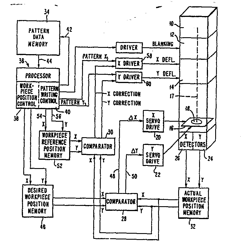
Beam source 10 is controllably turned on and off by blanking apparatus 12 and deflected
by deflector apparatus 14. The beam is incident on workpiece 18 on table 16. The position
of table 16 is detected by X, Y detectors 24, 26 and controlled by X, Y servos 20,
22. Servos 20, 22 are, in turn, contolled from comparator 28 which compares the desired
workpiece position obtained from pattern data memory 34 with the actual workpiece
position. The pattern data is used to control X, Y deflection drivers 58, 60 together
with X Y correction signals from comparator 30 and representing any difference between
the workpiece reference position and its actual position.
|
|
