| (19) |
 |
|
(11) |
EP 0 187 627 A1 |
| (12) |
EUROPEAN PATENT APPLICATION |
| (43) |
Date of publication: |
|
16.07.1986 Bulletin 1986/29 |
| (22) |
Date of filing: 15.11.1985 |
|
|
| (84) |
Designated Contracting States: |
|
AT DE FR GB IT SE |
| (30) |
Priority: |
12.12.1984 SE 8406332
|
| (71) |
Applicant: Flygt AB |
|
S-171 25 Solna (SE) |
|
| (72) |
Inventor: |
|
- Carlsson, Valdemar
S-171 17 Solna (SE)
|
| (74) |
Representative: Larsson, Sten |
|
Flygt AB
Box 1309
171 25 Solna
171 25 Solna (SE) |
|
| |
|
(57) The invention concerns a seal device to be arranged in the inlet to a centrifugal
pump.
The seal device (6, 7, 8) consists of a ring (6) of a rigid material and at least
one ring (7,8) of an elastic material. The latter ring provides for a good sealing,
even when the gap width varies.
|
|
[0001] The invention concerns a seal device for sealing the gap between a pump impeller
and a surrounding non-rotating part.
[0002] At pumps having rotary impellers, for instance centrifugal pumps, where the pumped
medium is sucked into the center of the impeller and leaves it at the perphery, it
is important that the inlet part of the impeller is well adapted to the surrounding
pump housing and that pumped medium is prevented from flowing back into the pump inlet.
A back flow, caused by the higher pressure in the pump housing, means losses as well
as an undesired turbulence in the inlet. In addition a concentration of pollutions
may occur in the gap between the impeller and the inlet of the pump housing.
[0003] In order to obtain the necessary sealing between the impeller and the non-rotary
parts, it is common to arrange a wear part made of rubber, on the non-rotary part
and let the impeller be in contact with that part during rotation. In this way an
effective sealing is obtained as long as the wear part is intact. When pumping liquids
containing pollutions such as sand, fabric, plastic stripes etc, there is often a
clogging between the seal ring and the impeller, which means frequent and expensive
service stops. As the pollutions drag the impeller, the energy demand increases. This.
demand is further increased by flexure of the shaft which means that intermittent
contacts occur between the impeller and the pump housing.
[0004] One way to solve this problem is to arrange a mechanical seal between the impeller
and the housing. By designing the sealing surfaces radially, a good sealing may be
obtained, even when the gap width varies, (Swedish Patent Application No 8401821-4).
A disadvantage with this solution is a relatively high price and that significant
energy losses may occur.
[0005] The purpose of this invention is thus to replace the wear parts made of rubber or
the like and the mechanical seal resp by a special seal ring, preferably arranged
in the pump inlet, which ring eliminates the disadvantages mentioned. This is obtained
by help of the device stated in the following claims.
[0006] The invention is described more closely below with reference to the enclosed drawing.
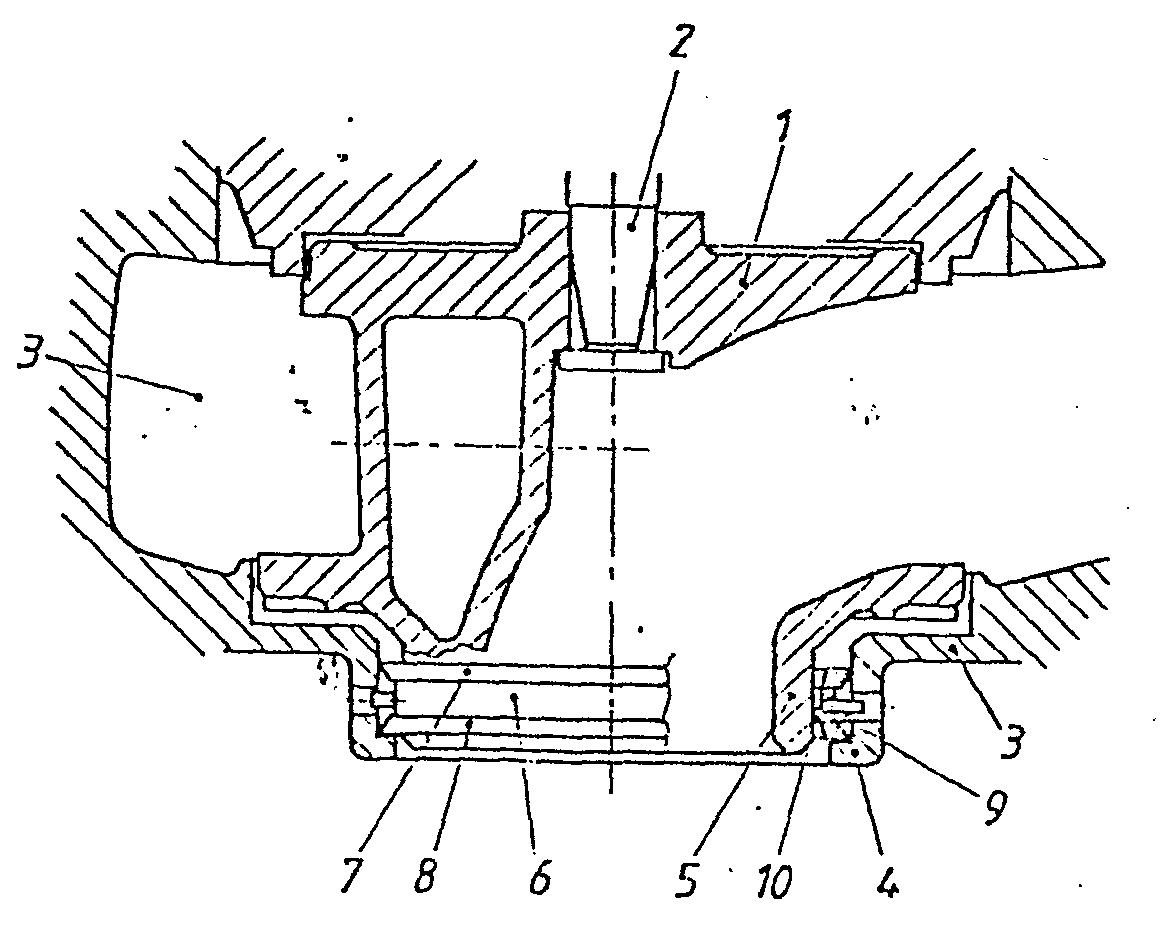
[0007] In the drawing 1 stands for an impeller on a rotatable shaft 2 in a pump housing
3. 4 and 5 stand for the inlet parts of the housing and the impeller resp. 6, 7, 8
stand for a seal ring, while 9 and 10 are gaps between the housing and the ring and
the ring and the impeller resp.
[0008] As previously mentioned the pumped medium is sucked into and through the pump inlet
5 and leaves it at its periphery. In order to make it possible for the impeller to
rotate freely, a certain gap is necessary between the impeller inlet and the inlet
of the housing. At the same time there is an ambition to make the gap as narrow as
possible in order to minimize the back flow from the inner of the pump housing caused
by the pressure difference between that and the surroundings.
[0009] According to the invention a seal ring 6, 7, 8 is arranged in the gap between the
impeller 1 and the pump housing 3. The ring is locked against turning, but is radially
movable. The ring is so formed that it resiliently seals the gap 9 towards the housing.
For that purpose at least one part 7, 8 of the ring is made of a flexible material
such as rubber or soft plastic and abuts the pump housing inlet 4. This gap, the width
of which may vary considerably, depending on the fact that the impeller oscillates
during rotation, is then effectively sealed. The flexible part 7, 8 is then preferably
formed like a tounge or has a cross section which simplifies an adaption to every
momentanous gap.
[0010] The gap 10 between the seal ring and the impeller is formed with a minimum width
such, that a permanent, strong abutment between the impeller and the ring never occurs.
[0011] The seal ring can for instance be composed of a rigid part 6 made of brass, cast
iron of hard plastic and one or several parts 7, 8 made of a non rigid material such
as rubber or soft plastic. It is however also possible to make the ring in one single
part which has the requested qualities concerning adaption of the width to actual
gap width.
1. A device for obtaining a sealing between a rotary part, such as a pump impeller,
and a non-rotary part, such as a pump housing surrounding the impeller, characterized
in, that the gap between the two parts (1) and (3) resp is sealed by a movable seal
ring (6, 7, 8), which automatically adapts its position in the gap in dependance of
the width, which latter may vary depending on a flexure of the rotary shaft (2).
2. A device according to claim 1, characterized in, that the seal ring (6, 7, 8) divides
the gap between the impeller (1) and the pump housing (3) into two gaps (9) and (10)
resp, the former, the width of which may vary considerably, is sealed by one or several
flexible parts (7, 8) of the seal ring while the latter gap (10) between the impeller
(1) and the seal has a minimum width.
3. A device according to claim 1, characterized in, that the seal ring (6, 7, 8) is
non-rotary but radially movable with regard to the pump housing (3).
4. A device according to claim 1, characterized in, that the seal ring consists of
a ring (6) of a rigid material and at least one ring (7, 8) made of a flexible material.
5. A device according to claim 1, characterized in, that the seal ring is manufactured
in one single part.
