| (19) |
 |
|
(11) |
EP 0 059 726 B1 |
| (12) |
EUROPEAN PATENT SPECIFICATION |
| (45) |
Mention of the grant of the patent: |
|
11.03.1987 Bulletin 1987/11 |
| (22) |
Date of filing: 04.09.1981 |
|
| (86) |
International application number: |
|
PCT/AU8100/127 |
| (87) |
International publication number: |
|
WO 8201/071 (01.04.1982 Gazette 1982/09) |
|
| (54) |
WATER PURITY MEASUREMENT
MESSEN DER WASSERREINHEIT
MESURE DE LA PURETE DE L'EAU
|
| (84) |
Designated Contracting States: |
|
CH DE FR GB LI NL SE |
| (30) |
Priority: |
12.09.1980 AU 5552/80
|
| (43) |
Date of publication of application: |
|
15.09.1982 Bulletin 1982/37 |
| (71) |
Applicant: THE COMMONWEALTH OF AUSTRALIA |
|
Canberra
Australian Capital Territory 2600 (AU) |
|
| (72) |
Inventor: |
|
- VARGA, Istvan K.
Windsor Gardens, S.A. 5087 (AU)
|
| (74) |
Representative: Billington, Lawrence Emlyn et al |
|
Haseltine Lake & Co.,
Imperial House,
15-19 Kingsway
London WC2B 6UD
London WC2B 6UD (GB) |
|
| |
|
| Note: Within nine months from the publication of the mention of the grant of the European
patent, any person may give notice to the European Patent Office of opposition to
the European patent
granted. Notice of opposition shall be filed in a written reasoned statement. It shall
not be deemed to
have been filed until the opposition fee has been paid. (Art. 99(1) European Patent
Convention).
|
[0001] This invention relates to the measurement of water purity, particularly where the
purity is required to be measured in fractions of a part per million.
[0002] With the enormous expansion of activity in Semiconductor Technology over the last
decade or so, has come the need for chemicals of hitherto unheard of purity. We see
reference to materials which typically have purity levels measured in fractions of
a part per million being used routinely in wet-way chemical processes on silicon wafers.
These materials are used in aqueous solutions, which in turn places a very considerable
emphasis on the purity of the solvent, water. The presence of traces of inorganic
contaminants in both the chemicals being used and in the water can lead to irreversible
modification of the semiconductor materials during processing.
[0003] The normal technique used to assess the purity of water is to measure the concentration
of the contaminants in their ionised state using standard conductivity methods. This
method, while being most satisfactory at normal impurity levels such as in tap water,
distilled water, and the like, becomes extremely difficult when the water approaches
the ultimate in chemical purity with resistivities of 10's of MQcm, the level required
in the semiconductor industry.
[0004] US-A-3 502 965 discloses a method for measuring the charge condition in a sample
stream of contaminated water. The water flows through a cell comprising a pipe of
insulating material disposed between electrodes arranged to measure the electromotive
force developed by the water flowing through the cell.
[0005] GB-A-2 034 902 discloses a system for monitoring a low conductivity liquid carrying
an electrostatic charge (due to the tribo-electric effect) and flowing along a pipeline,
comprising two separately insulated conductive wall sections of the pipeline.
[0006] In the course of our research we have found that a tribo-electric e.m.f. which is
generated due to friction in flowing water, particularly when it is transported through
insulating plastic pipes, can be used to measure water purity. In fact, this e.m.f.
can cause damage to highly reflecting surfaces in water cooled pumping cavities in
a solid state laser. In this invention use is made of this tribo-electric effect to
measure the resistivity of the water, an inverse function of the ionic contamination
and hence its purity, in a very simple measuring cell.
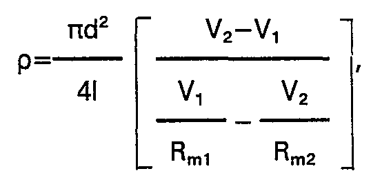
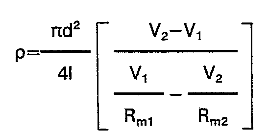
[0007] According to a first aspect of the present invention there is provided a method for
measuring the purity of water, which comprises causing the water to flow through a
cell comprising a single pipe section of insulating material disposed between electrodes
arranged to measure the electromotive force generated by the water flowing through
the cell by connecting to the said electrodes a voltmeter of sufficiently high input
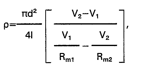
resistance as to be ignored, characterised by calculating the resistivity p of the
water from the tribo-electric electromotive force generated, the value of the resistivity
p being indicative of the level of purity of the water, by connecting across the voltmeter
a pair of alternately selectable parallel different value resistances R
m1 and R
m2' and by determining the resistivity p of the water by the formula
wherein d is the internal diameter of the single pipe section, I is its length, and
V
1 and V
2 are the tribo-electric voltages detected by the voltmeter when the resistances R
m1 and R
m2 respectively are switched in parallel with the voltmeter.
[0008] According to a second aspect of the present invention there is provided a device
for measuring the purity of water which comprises a cell having a pipe in it arranged
for water to be measured to flow therethrough, said pipe being formed of electrically
insulating material, an electrode at each end of the said pipe, and measuring means
including a voltmeter connected to said electrodes having a sufficiently high input
resistance as to be ignored, characterised by a pair of alternately selectable parallel
different value resistances connected across the voltmeter, to enable said voltmeter
to detect the two corresponding tribo-electric voltages V" V
2 necessary for the evaluation of the formula used in connection with the aforementioned
first aspect of the present invention.
[0009] In specific applications, such as the semi- conductor technology referred to above,
where generally the pipes are looped and the two ends are at the same potential, the
invention may be modified by having electrodes arranged to provide differing characteristics
from adjacent sections of the cell so formed. This can be achieved by using materials
of different characteristic or by having differing diameters in the cell to give a
different velocity and hence achieve a different tribo-electric e.m.f.
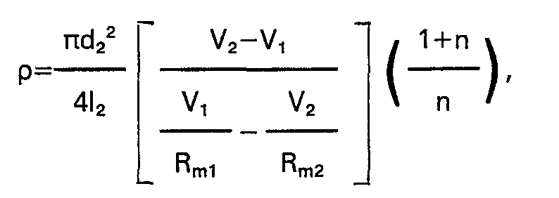
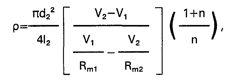
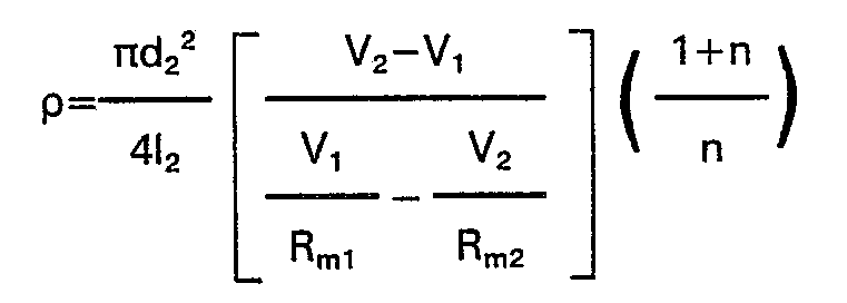
[0010] According to a third aspect of the present invention there is provided a method for
measuring the purity of water, which comprises causing the water to flow through a
cell in the form of a pipe of insulating material disposed between electrodes arranged
to measure the electromotive force generated by the water flowing through the cell
by connecting to the said electrodes a voltmeter of sufficiently high input resistance
as to be ignored, characterised in that the pipe comprises two pipe sections with
the same internal diameter and of insulating material having different characteristics
producing different partial cell voltages by the tribo-electric effect, the pipe having
an intermediate electrode between the two pipe sections, the level of purity of the
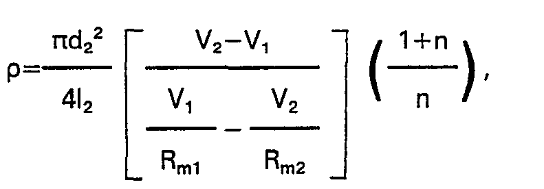
water being indicated by the value of the resistivity p thereof, the resistivity p
being found by interconnecting the end electrodes electrically and connecting said
voltmeter to the intermediate electrode on the one hand and the end electrodes on
the other hand, and across it a pair of alternately selectable parallel different
value resistances R
m1 and R
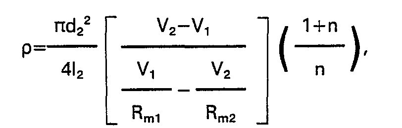
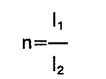
m2, and determining the resistivity p of the water by the formula
wherein d
2 and 1
2 are the internal diameter and length of one pipe section, V
1 and V
2 are the tribo-electric voltages detected by the voltmeter when the resistances R
m1 and R
m2 respectively are switched in parallel with the voltmeter, and
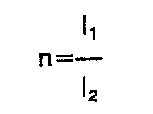
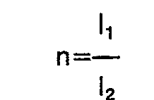
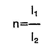
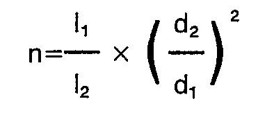
where 1
1 is the length of the other pipe section.
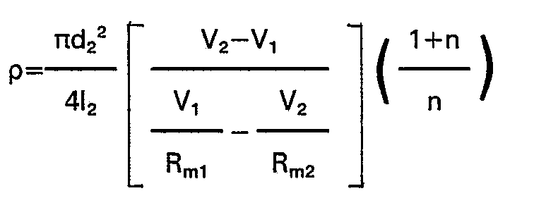
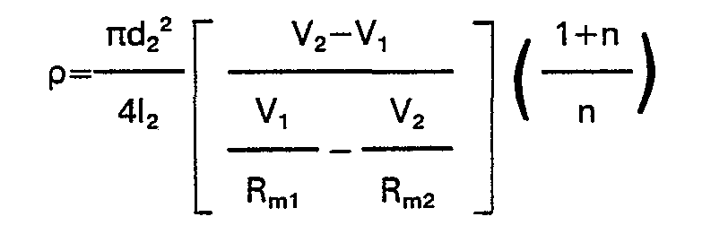
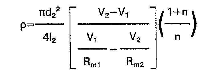
[0011] According to a fourth aspect of the present invention there is provided a method
for measuring the purity of water, which comprises causing the water to flow through
a cell in the form of a pipe of insulating material disposed between electrodes arranged
to measure the electromotive force generated by the water flowing through the cell,
by connecting to the said electrodes a voltmeter of sufficiently high input resistance
as to be ignored, characterised in that the pipe comprises two pipe sections of the
same insulating material, and with different internal diameters producing different
partial cell voltages by the tribo-electric effect, the pipe having an intermediate
electrode between the two pipe sections, the level of purity of the water being indicated
by the value of the resistivity p thereof, which is found by interconnecting the end
electrodes electrically and connecting said voltmeter to the intermediate electrode
on the one hand and the end electrodes on the other hand, and across it a pair of
alternately selectable parallel different value resistances R
m1 and R
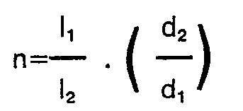
m2, and determining the resistivity p of the water by the formula
wherein d
2 and I
2 are the internal diameter and length of one pipe section, V
1 and V
2 are the tribo-electric voltages detected by the voltmeter when the resistances R
m1, and R
m2, respectively are switched in parallel with the voltmeter, and

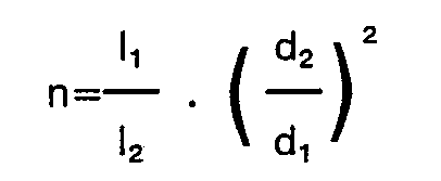
wherein 1
1 and d
1 are the length and internal diameter of the other pipe section.
[0012] Embodiments of the device according to the aforementioned second aspect of the present
invention enable the evaluation of the formulas used in connection with the aforementioned
third or fourth aspect of the present invention.
[0013] While the invention has been based on the semi-conductor industry, application of
this effect could be widespread in many chemical plants and other industries.
[0014] In the case of where the two ends of the pipe are at a common potential, two dissimilar
cell sections are preferably used which vary by wall material characteristic, such
as by using for instance a material known under the trade mark "Delrin" for one section
of the cell and material known under the trade mark "Perspex" for the other section
of the cell, arranged coextensive the one with the other with an end electrode at
each end of the cell so formed and an intermediate electrode between the two sections.
[0015] Instead of using two sections of the cell of dissimilar material the two sections
can be of similar material but vary from each other by the internal diameter of the
pipe sections.
[0016] For a better understanding of the invention and to show how it may be put into effect
reference will now be made by way of example to the accompanying drawings in which:
Fig. 1A is a schematic central section of a cell formed of a section of insulating
material having an electrode at each end, B showing the equivalent electrical circuit,
and C the measuring circuit;
Fig. 2A is a similar view to Fig. 1A but showing the assembly used when the pipe is
looped, in which case two insulating sections with electrodes at each end are used,
B again showing the equivalent circuit, and C the measuring circuit of this type of
cell;
Fig. 3 is a further schematic view showing a cell with varying diameters as opposed
to varying materials, the equivalent circuits being similar to B and C of Fig. 2;
Fig. 4 is a central longitudinal section showing how the device of Fig. 1 can be constructed;
and
Fig. 5 is a view similar to Fig. 4 but showing construction of a cell as shown in
Fig. 3.
[0017] Fig. 1 shows a pipe section 1 of insulating material having electrodes 2 and 3 at
the ends, the pipe section 1 being connected between pipes 4 and 5 through which the
water flow occurs. As shown in Fig. 4 this can be constructed by threading the two
ends of the plastic pipe section 1 and screwing to it a pair of electrodes 2 and 3
into which the ends of the pipes 4 and 5 project. Wedge nuts 6 and 7 lock the pipes
4 and 5 in position and effect a seal.
[0018] The device of Fig. 2 has two pipe sections 10 and 11 of insulating material, which
differ in their physical characteristic, using three electrodes 12, 13 and 14. Electrodes
12 and 14 respectively joined to the ends of the pipes 15 and 16 are connected externally
by an electrical short circuit. Readings are taken between electrodes 13 and either
electrode 12 or electrode 14. The actual construction of this can again be similar
to the form illustrated in Fig. 4 excepting that an intermediate electrode would be
used, screwing into both of the pipe sections 10 and 11 of different insulating material.
[0019] The form illustrated in Fig. 3 uses pipe sections 20 and 21 of different internal
diameters with electrodes 22, 23 and 24. All this is fitted between the ends of the
pipes 25 and 26, and could be similar to the form illustrated in Fig. 5, in which
two end electrodes 22 and 24 are joined by an external sleeve 27 in which the pipe
sections 20 and 21 of similar insulating material are disposed with the intermediate
electrode 23 between them. The end electrodes 22 and 24 again have sockets to take
the ends of the pipes 25 and 26 which are locked to the electrodes 22 and 24 by wedge
nuts 28 and 29 which screw on to the electrodes 22 and 24. Insulation 30 isolates
the intermediate electrode 23 from the sleeve 27.
[0020] The method of calculating the water purity is as follows:
Referring first to the simple cell of Fig. 1, the equivalent electrical circuit may
be considered as shown in Fig. 1 B and the measuring circuit Fig. 1C where
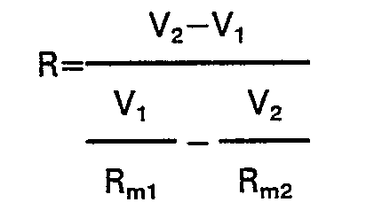
[0021] To obtain a value for R, the water resistance, two measurements are made using two
resistors R
m1 and R
m2 giving two voltages V
1 and V
2 respectively.
[0022] R may then be derived from the following relation:
If dissimilar plastics are used for the pipes or if the flow rates are modified in
certain areas of the pipe by changing the diameter, then once again the e.m.f. can
be measured.
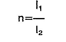
[0023] When the cell is of dissimilar materials and uniform flow velocity, the two outer
electrodes 12 and 14 are short circuited electrically and the measurement is made
across electrodes 13 and 14 using the formula:
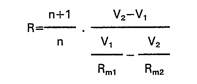
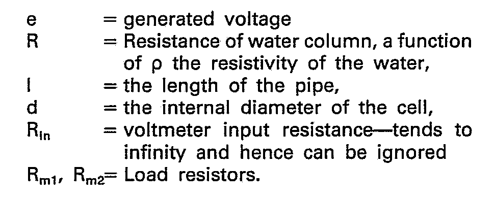
where
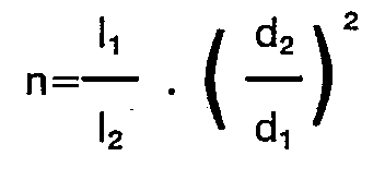
[0024] When using similar materials but different diameters the measuring circuit of Fig.
2C applies and the formula from which R can be calculated is as follows:
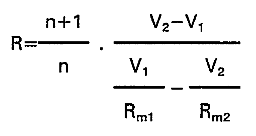
where
[0025] From R the water electrical resistance, p the resistivity can be calculated as:
[0026] Cells having an optimum of output voltage for a given system may be designed. A cell
can be tailored by choice of cell length, diameter, and insulating materials.
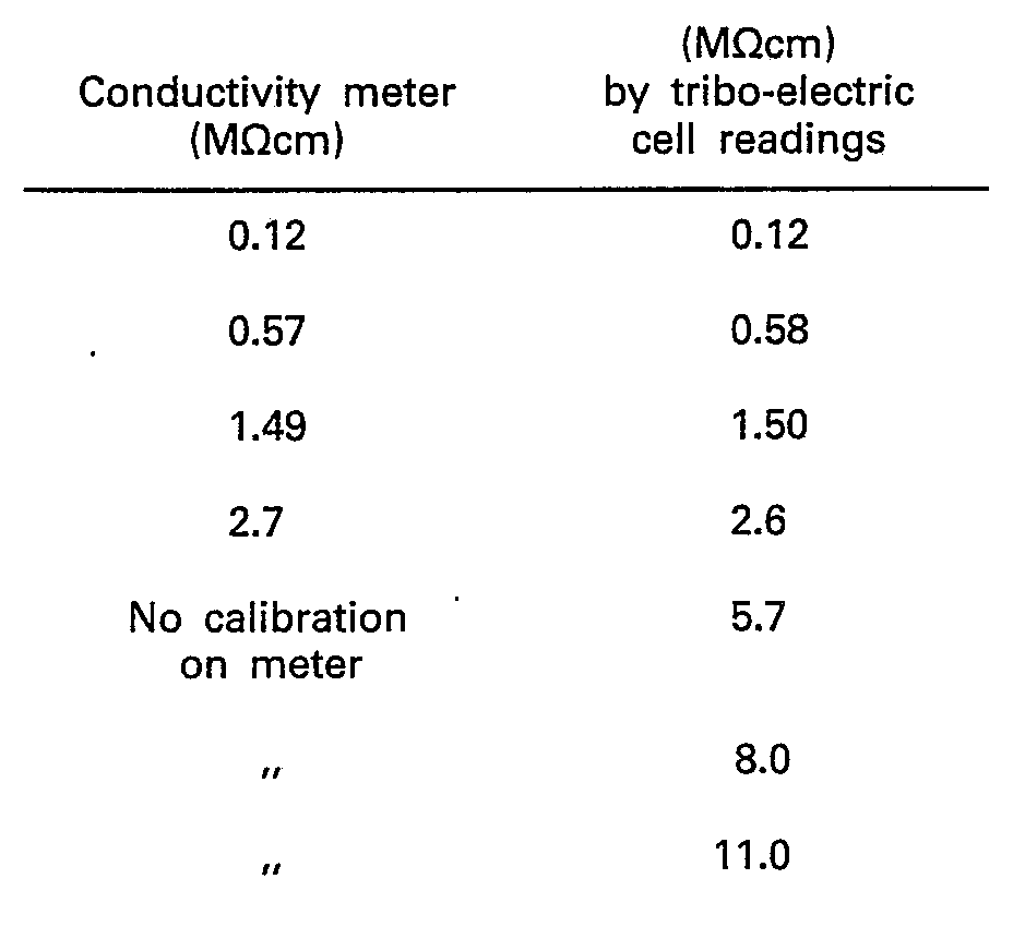
[0027] Practical results have shown that a simple cell having the configuration as in Fig.
4, and inserted in a working system in which the system "loops" are very large and
hence electrically isolated has worked extremely well. Results of checks against a
conventional conductivity cell system are shown in the following table. The tribo-electric
cell was inserted in a working water treatment plant and the results calculated from
the tribo-electric cell are shown against the readings given by the standard conductivity
cell system.
[0028] Tests on the more complex system of Fig. 5 confirm the theoretical tribo-electric
model of the system. The voltages generated by the differences of cell insulating
materials, differing diameters and differing cell lengths have been as predicted.
Inner wall finish of the plastic tube does not appear to have any marked effect in
the first instance on cell voltage; in our measurements any variations are lumped
with the "tribo-electric" constant K for that particular cell. In all tests, it is
assumed that flow-rates have been maintained constant for the period of the measurement,
several seconds only.
1. A method for measuring the purity of water, which comprises causing the water to
flow through a cell comprising a single pipe section of insulating material disposed
between electrodes arranged to measure the electromotive force generated by the water
flowing through the cell by connecting to the said electrodes a voltmeter of sufficiently
high input resistance as to be ignored, characterised by calculating the resistivity
p of the water from the tribo-electric electromotive force generated, the value of
the resistivity p being indicative of the level of purity of the water, by connecting
across the voltmeter a pair of alternately selectable parallel different value resistances
R
m1 and R
m2, and by determining the resistivity p of the water by the formula
wherein d is the internal diameter of the single pipe section, I is its length, and
V
1 and V
2 are the tribo-electric voltages detected by the voltmeter when the resistances R
m1 and R
m2, respectively are switched in parallel with the voltmeter.
2. A method for measuring the purity of water, which comprises causing the water to
flow through a cell in the form of a pipe of insulating material disposed between
electrodes arranged to measure the electromotive force generated by the water flowing
through the cell by connecting to the said electrodes a voltmeter of sufficiently
high input resistance as to be ignored, characterised in that the pipe comprises two
pipe sections with the same internal diameter and of insulating material having different
characteristics producing different partial cell voltages by the tribo-electric effect,
the pipe having an intermediate electrode between the two pipe sections, the level
of purity of the water being indicated by the value of the resistivity p thereof,
the resistivity p being found by interconnecting the end electrodes electrically and
connecting said voltmeter to the intermediate electrode on the one hand and the end
electrodes on the other hand, and across it a pair of alternately selectable parallel
different value resistances R
m1 and R
m2. and determining the resistivity p of the water by the formula
wherein d
2 and I
2 are the internal diameter and length of one pipe section, V
1 and V
2 are the tribo-electric voltages detected by the voltmeter when the resistances R
m1 and R
m2 respectively are switched in parallel with the voltmeter, and
where 1
1 is the length of the other pipe section.
3. A method for measuring the purity of water, which comprises causing the water to
flow through a cell in the form of a pipe of insulating material disposed between
electrodes arranged to measure the electromotive force generated by the water flowing
through the cell by connecting to the said electrodes a voltmeter of sufficiently
high input resistance as to be ignored, characterised in that the pipe comprises two
pipe sections of the same insulating material, and with different internal diameters
producing different partial cell voltages by the tribo-electric effect, the pipe having
an intermediate electrode between the two pipe sections, the level of purity of the
water being indicated by the value of the resistivity p thereof, which is found by
interconnecting the end electrodes electrically and connecting said voltmeter to the
intermediate electrode on the one hand and the end electrodes on the other hand, and
across it a pair of alternately selectable parallel different value resistances R
m1 and R
m2, and determining the resistivity p of the water by the formula
wherein d
2 and I
2 are the internal diameter and length of one pipe section, V
1 and V
2 are the tribo-electric voltages detected by the voltmeter when the resistances R
m1 and R
m2 respectively are switched in parallel with the voltmeter, and
wherein 1
1 and d
1 are the length and internal diameter of the other pipe section.
4. A device for measuring the purity of water which comprises a cell having a pipe
(1) in it arranged for water to be measured to flow therethrough, said pipe (1) being
formed of electrically insulating material, an electrode (2, 3) at each end of the
said pipe (1), and means to measure the electromotive force (e) generated by the water
flowing through the cell, said means including a voltmeter (V) connected to said electrodes
(2, 3) having a sufficiently high input resistance as to be ignored, characterised
by a pair of alternately selectable parallel different value resistances Rm1, Rm2 connected across the voltmeter (V) to enable said voltmeter (V) to detect the two
corresponding tribo-electric voltages V1, V2 necessary for the evaluation of the formula set out in claim 1.
5. A device according to claim 4, characterised in that said pipe (1) comprises two
different sections (10, 11; 20, 21) having different characteristics and producing
different partial cell tribo-electric voltages (e1, e2), and an intermediate electrode (13; 23) between the said different sections (10,
11; 20, 21).
6. A device according to claim 5, characterised in that said sections (10, 11) differ
by the nature of the insulating material from which each said section (10, 11) is
formed.
7. A device according to claim 5, wherein the said sections (20, 21) differ by the
internal cross-sectional dimension.
8. A device according to claim 5 characterised in that the said sections (10, 11)
are of the same internal diameter for constant velocity flow therethrough and the
said electrodes (12, 14) disposed at each end of the said pipe are connected together
electrically and the said measuring means (V), Rm1, Rm2 are connected to the said electrodes (12, 14) on the one hand, and the said intermediate
electrode (13) on the other hand, and in that the device evaluates the formula set
out in claim 2.
9. A device according to claim 5 characterised in that the said sections (20, 21)
are of different internal diameter for different velocity flow therethrough and the
said electrodes (22, 24) disposed at each end of the said pipe are connected together
electrically and the said measuring means (V), Rm1, Rm2 are connected to the said end electrodes (22, 24) on the one hand and the said intermediate
electrode (23) on the other hand, and in that the device evaluates the formula set
out in claim 3.
10. A device according to claim 4, characterised in that the pipe (1) is secured at
each end to the respective electrode (2, 3) having a socket to receive one end of
a divided pipe line (4, 5) into which said pipe (1) is inserted, each said electrode
(2, 3) including means to engage and hold the said pipe line end.
11. A device according to claim 5, characterised in that the two electrodes (22, 24)
arranged on the ends of the said pipe are held together by a conductive sleeve (27)
engaging the said electrodes (22, 24), said electrodes (22, 24) each having a socket
to receive one end of a divided pipe line (25, 26) into which said pipe is inserted,
and each electrode (22, 24) having means to engage and hold the associated pipe line
end, and in that the intermediate electrode (23) is insulated from the said sleeve
(27) and arranged to have an external electrical connection.
1. Verfahren zur Messung der Wasserreinheit mit einer vom Wasser zu durchströmenden
Meßzelle, die einen aus isolierendem Material bestehenden Rohrabschnitt . aufweist,
der zwischen zwei Elektroden angeordnet ist, welche zur Messung der durch den Wasserdurchfluß
durch die Meßzelle erzeugten elektromotorischen Kraft an ein Voltmeter mit ausreichend
hohem Eingangswiderstand angeschlossen sind, dadurch gekennzeichnet, daß als Meßgröße
zur Bestimmung des den Wasserreinheitsgrad kennzeichnenden spezifischen Widerstandes
p des Wassers die erzeugte tribo-elektrische Kraft dient, wobei zwei unterschiedliche
Parallelwiderstände R
m1, R
m2 wahlweise parallel zum Voltmeter zugeschaltet werden und sich der spezifische Widerstand
des Wassers aus der Formel
ergibt, wobei d den Innendurchmesser des Rohrabschnittes, 1 seine Länge und V
1 bzw. V
2 die mittels des Voltmeters bei paralleler Zuschaltung des Parallelwiderstandes R
m1 bzw. R
m2 gemessene tribo-elektrische Spannung bedeuten.
2. Verfahren zur Messung der Wasserreinheit mit einer vom Wasser zu durchströmenden
röhrenförmigen Meßzelle aus isolierendem Material, die zwischen Elektroden angeordnet
ist, welche zur Messung der durch den Wasserdurchfluß durch die Meßzelle erzeugten
elektromotorischen Kraft an ein Voltmeter mit ausreichend hohem Eingangswiderstand
angeschlossen sind, dadurch gekennzeichnet, daß die röhrenförmige Meßzelle zwei Rohrabschnitte
mit gleichem Innendurchmesser aufweist, die für Abgabe verschiedener durch den tribo-elektrischen
Effekt erzeugten Teilzellspannungen aus unterschiedlichem Isolationsmaterial bestehen,
zwischen den beiden Rohrabschnitten eine Zwischenelektrode vorgesehen wird, die zur
Ermittlung des den Wasserreinheitsgrad kennzeichnenden spezifischen Widerstandes p
des Wassers an die eine Seite des Voltmeters angeschlossen wird und die elektrisch
miteinander zu verbindenden Endelektroden an die andere Seite gelegt werden und zwei
verschiedene Parallelwiderstände R
m1, R
m2 wahlweise parallel zum Voltmeter zugeschaltet werden, wobei sich der spezifische
Widerstand des Wassers aus der Formel
ergibt, worin d
2 den Innendurchmesser und I
2 die Länge des einen Rohrabschnittes, V
1 bzw. V
2 die mittels des Voltmeters bei paralleler Zuschaltung des Parallelwiderstandes R
m1 bzw. R
m2 gemessene tribo-elektrische Spannung und
bedeuten, wobei 1
1 die Länge des anderen Rohrabschnittes ist.
3. Verfahren zur Messung der Wasserreinheit mit einer vom Wasser zur durchströmenden
röhrenförmigen Meßzelle aus isolierendem Material, die zwischen Elektroden angeordnet
ist, welche zur Messung der durch den Wasserdurchfluß durch die Meßzelle erzeugten
elektromotorischen Kraft an ein Voltmeter mit ausreichend hohem Eingangswiderstand
angeschlossen sind, dadurch gekennzeichnet, daß die röhrenförmige Meßzelle zwei Rohrabschnitte
aus gleichem isolierendem Material enthält, die für Abgabe unterschiedlicher durch
den tribo-elektrischen Effekt erzeugten Teilzellspannungen unterschiedliche Innendurchmesser
aufweisen, zwischen den beiden Rohrabschnitten eine Zwischenelektrode vorgesehen wird,
die zur Ermittlung des den Wasserreinheitsgrad kennzeichnenden spezifischen Widerstandes
p des Wassers an die eine Seite des Voltmeters angeschlossen wird und die elektrisch
miteinander zu verbindenen Endelektroden an die andere Seite gelegt werden und zwei
verschiedene Parallelwiderstände R
m1, R
m2 wahlweise zum Voltmeter parallel zugeschaltet werden, wobei sich der spezifische
Widerstand des Wassers aus der Formel
ergibt, worin d
2 und 1
2 den Innendurchmesser und die Länge eines Rohrabschnittes, V
1 bzw. V
2 die mittels des Voltmeters bei paralleler Zuschaltung des Parallelwiderstandes R
m1, bzw. Rm2 gemessene tribo-elektrische Spannung und
bedeuten, wobei I
1 und d
1 die Länge und der Innendurchmesser des anderen Rohrabschnittes sind.
4. Vorrichtung zur Messung der Wasserreinheit mit einer Meßzelle, die ein vom Wasser
zu durchströmendes Rohr (1) aus isolierendem Material mit an beiden Enden des Rohres
(1) angeordneten Elektroden (2, 3) aufweist, und mit zur Messung der durch den Wasserdurchfluß
durch die Meßzelle erzeugten elektromotorischen Kraft (e) ausgebildeten Einrichtungen,
die ein mit den Elektroden (2, 3) verbundenes Voltmeter (V) mit ausreichend hohem
Eingangswiderstand enthalten, dadurch gekennzeichnet, daß zur Messung der zwei entsprechenden
tribo-elektrischen Spannungen V1, V2 für die Auswertung der Formel nach Anspruch 1 zwei verschiedene Parallelwiderstände
Rm1, Rm2 wahlweise parallel zum Voltmeter (V) zuschaltbar sind.
5. Vorrichtung nach Anspruch 4, dadurch gekennzeichnet, daß das Rohr (1) für die Erzeugung
unterschiedlicher tribo-elektrischer Teilzelispannungen (el, e2) zwei verschiedene Abschnitte (10, 11; 20, 21) mit unterschiedlichen Parametern
enthält und eine Zwischenelektrode (13; 23) zwischen den beiden Abschnitten (10, 11;
20, 21) vorgesehen ist.
6. Vorrichtung nach Anspruch 5, dadurch gekennzeichnet, daß die beiden Abschnitte
(10, 11) aus unterschiedlichem isolierenden Material bestehen.
7. Vorrichtung nach Anspruch 5, dadurch gekennzeichnet, daß die beiden Rohrabschnitte
(20, 21) unterschiedliche Innendurchmesser aufweisen.
8. Vorrichtung nach Anspruch 5, dadurch gekennzeichnet, daß die Rohrabschnitte (10,
11) für konstante Wasserdurchfluß-Geschwindigkeit gleichen Innendurchmesser aufweisen,
daß die an jedem Ende des Rohres (1) angeordneten Elektroden (12, 14) elektrisch miteinander
verbunden sind und die Meßeinrichtungen (V), Rm1, Rm2 auf der einen Seite an die Endelektroden (12, 14) und auf der anderen Seite an die
Zwischenelektrode (13) angeschlossen sind, und daß die Formel nach Anspruch 2 ausgewertet
wird.
9. Vorrichtung nach Anspruch 5, dadurch gekennzeichnet, daß die Rohrabschnitte (20,
21) für unterschiedliche Wasserdurchfluß-Geschwindigkeiten verschiedene Innendurchmesser
aufweisen, daß die an jedem Ende des Rohres (1) angeordneten Endelektroden (22, 24)
elektrisch miteinander verbunden sind und die Meßeinrichtungen (V), Rm1, Rm2 auf der einen Seite an die Endelektroden (22, 24) und auf der anderen Seite an die
Zwischenelektrode (23) angeschlossen sind, und daß die Formel nach Anspruch 3 ausgewertet
wird.
10. Vorrichtung nach Anspruch 4, dadurch gekennzeichnet, daß das Rohr (1) an jedem
Ende an der entsprechenden Elektrode (2, 3) befestigt ist, die mit einer Fassung zum
Aufnehmen von einem Ende eines geteilten Leitungsrohres (4, 5) versehen ist, in die
das Rohr (1) eingesetzt ist, und jede Elektrode (2, 3) Einrichtungen zum Erfassen
und Halten des Leitungsrohrendes enthält.
11. Vorrichtung nach Anspruch 5, dadurch gekennzeichnet, daß die an den Enden des
Rohres angeordneten zwei Elektroden (22, 24) durch eine die beiden Elektroden (22,
24) ergreifende elektrisch leitende Hülse (27) zusammengehalten sind, jede der Elektroden
(22, 24) mit einer Fassung zum Aufnehmen von einem Ende eines geteilten Leitungsrohres
(25, 26) versehen ist, in die das Rohr eingesetzt ist, jede Elektrode (22, 24) Einrichtungen
zum Erfassen und Halten des entsprechenden Leitungsrohrendes enthält und daß die Zwischenelektrode
(23) gegenüber der Hülse (27) isoliert und für eine externe elektrische Verbindung
ausgebildet ist.
1. Méthode pour mesurer la pureté de l'eau, comprenant l'écoulement de l'eau à travers
une cellule constituée par une seule section tubulaire en matériau isolant, disposée
entre des électrodes montées de façon à mesurer le force électro-motrice, générée
par l'écoulement de l'eau à travers la cellule, par raccordement à ces électrodes
d'un voltmètre ayant une résistance d'entrée suffisamment élevée pour être négligée,
méthode caractérisée en ce que l'on calcule la résistivité p de l'eau à partir de
la force électro-motrice tribo-électrique générée, la valeur de la résistivité p indiquant
le niveau de pureté de l'eau, en branchant aux bornes de voltmètre une paire de résistances
R
m1 et R
m2 parallèles ayant des valeurs différentes et sélectionnables alternativement, et en
déterminant la résistivité p de l'eau à l'aide de la formule
dans laquelle d est le diamètre intérieur de la section tubulaire 1 est sa longueur,
et V, et V
2 sont les tensions tribo-électriques détectées par le voltmètre lorsque les résistances
R
m1 et R
m2 sont branchées respectivement en parallèle avec le voltmètre.
2. Méthode pour mesurer la pureté de l'eau, comprenant l'écoulement de l'eau à travers
une cellule ayant une forme tubulaire, en matériau isolant, disposée entre des électrodes
montées de façon à mesurer la force électro-motrice, générée par l'écoulement à travers
la cellule, par raccordement à ces électrodes d'un voltmètre ayant une résistance
d'entrée suffisamment élevée pour être négligée, méthode caractérisée en ce que le
tube comprend deux sections tubulaires ayant le même diamètre intérieur et constituées
par des matériaux isolants ayant des caractéristiques différentes produisant des tensions
partielles de cellules différentes par l'effet tribo-électrique, le tube ayant une
électrode intermédiaire entre les deux sections tubulaires, le niveau de pureté de
l'eau étant indiqué par la valeur de la résistivité p de cette eau, la résistivité
p étant trouvée par inter-connexion électrique des électrodes d'extrémité et raccordement
du voltmètre à l'électrode intermédiaire d'une part et aux électrodes d'extrémité
d'autre part, et raccordement de ce voltmètre à une paire de résistances R
m1 et R
m2 parallèles, de différentes valeurs et sélec-r tionnables alternativement, et par
détermination de la résistivité p de l'eau à l'aide de la formule
dans laquelle d
2 et I
2 sont le diamètre intérieur et la longueur d'une section tubulaire, V
i et V
2 sont les tensions tribo-électriques détectées par le voltmètre lorsque les résistances
R
m1 et R
m2 sont branchées respectivement en parallèle avec le voltmètre et
ou I
1 est la longueur de l'autre section tubulaire.
3. Méthode pour mesurer la pureté de l'eau comprenant l'écoulement de l'eau à travers
une cellule ayant la forme d'un tube en matériau isolant disposé entre des électrodes
montées de façon à mesurer la force électro-motrice générée par l'eau s'écoulant à
travers la cellule, pâr raccordement à ces électrodes d'un voltmètre ayant une résistance
d'entrée suffisamment élevée pour être négligée, méthode caractérisée en ce que le
tube comprend deux sections tubulaires constituées par le même matériau isolant et
ayant des diamètres intérieurs différents produisant des tensions partielles de cellule
différentes par l'effet tribo-électrique, le tube comportant une électrode intermédiaire
entre les deux sections tubulaires, le niveau de pureté de l'eau étant indiqué par
la valeur de la résistivité p de cette eau qui est trouvée par inter-connexion électrique
des électrodes d'extrémité et raccordement du voltmètre à l'électrode intermédiaire
d'une part et aux électrodes d'extrémité d'autre part et par raccordement aux bornes
de ce voltmètre d'une paire de résistances R
m1 et Rm2 parallèles, de différentes valeurs et sélectionnables alternativement, et
par la détermination de la résistivité p de l'eau à l'aide de la formule
dans laquelle d
2 et I
2 sont le diamètre intérieur et la longueur de l'une des sections tubulaires, V
1 et V
2 sont les tensions tribo-électriques détectées par le voltmètre lorsque les résistances
R
m1 et R
m2 sont branchées respectivement en parallèle avec le voltmètre, et
où 1
1 et d
1 sont la longueur et le diamètre intérieur de l'autre section tubulaire.
4. Dispositif pour mesurer la pureté de l'eau, constitué par une cellule comprenant
un tube (1) disposé de façon que l'eau à mesurer s'écoule à travers le tube, le tube
(1) étant constitué par un matériau isolant électrique, une électrode (2, 3) à chaque
extrémité du tube (1) et un moyen pour mesurer la force électro-motrice (e) générée
par l'écoulement de l'eau à travers la cellule, ce moyen comprenant un voltmètre (V)
raccordé aux électrodes (2, 3) et ayant une résistance d'entrée suffisamment élevée
pour être négligée, dispositif caractérisé par une paire de résistances Rm1, Rm2 parallèles, de valeurs différentes, sélectionnables alternativement, raccordées aux
bornes du voltmètre V de façon à permettre à ce voltmètre V de détecter les deux tensions
tribo-électriques correspondantes V1, V2 nécessaires pour l'évaluation de la formule présentée dans la revendication.
5. Dispositif selon la revendication 4 caractérisé en ce que le tube (1) comprend
deux sections différentes (10, 11; 20, 21) ayant des caractéristiques différentes
et produisant des tensions tribo-électriques partielles de cellule (e1, et e2) différentes et une électrode intermédiaire (13; 23) entre les dites sections (10,
11; 20, 21 ) différentes.
6. Dispositif selon la revendication 5 caractérisé en ce que les sections (10,11)
diffèrent entre elles par la nature du matériau isolant qui constitue chacune des
sections (10, 11).
7. Dispositif selon la revendication 5 caractérisé en ce que les sections (20, 21)
différent entre elles par les dimensions de sections transversales intérieures.
8. Dispositif selon la revendication 5 caractérisé en ce que les sections (10, 11)
présentent le même diamètre intérieur pour permettre un écoulement d'une vitesse constante
à travers ces sections et que les électrodes (12, 14) disposées à chaque extrémité
du tube sont raccordées électriquement entre elles, et que les moyens de mesure (V),
Rm1, Rm2 sont raccordés aux électrodes (12, 14) d'une part et à l'électrode intermédiaire
(13) d'autre part et que le dispositif permet d'évaluer la formule présentée dans
la revendication 2.
9. Dispositif selon la revendication 5 caractérisé en ce que les sections (20, 21)
ont des diamètres intérieurs différents permettant des vitesses d'écoulement différentes
à travers ces sections et que les électrodes (22, 24) disposées à chaque extrémité
du tube sont raccordées électriquement entre elles et que les moyens de mesure (V)
Rm1, Rm2 sont raccordés aux électrodes d'extrémité (22, 24) d'une part et à l'électrode intermédiaire
(23) d'autre part et que le dispositif permet d'évaluer la formule présentée dans
la revendication 3.
10. Dispositif selon la revendication 4, caractérisé en ce que le tube (1) est fixé,
à chaque extrémité, à l'électrode correspondante (2, 3) ayant un embout permettant
de recevoir une extrémité d'un conduit tubulaire divisé (4, 5) dans lequel le tube
(1) est inséré, chacune des électrodes (2, 3) comprenant un moyen pour fixer et maintenir
l'extrémité du conduit tubulaire.
11. Dispositif selon la revendication 5, caractérisé en ce que les deux électrodes
(22, 24) disposés aux extrémités du tube sont maintenues ensemble par un manchon conducteur
(27) raccordé aux électrodes (22, 24), les électrodes (22, 24) ayant chacune un embout
permettant de recevoir une extrémité d'un conduit tubulaire divisé (25, 26) dans lequel
est inséré le tube, et chaque électrode (22, 24) ayant un moyen pour fixer et maintenir
l'extrémité correspondante du conduit tubulaire, et que l'électrode intermédiaire
(23) est isolée du manchon (27) et agencée de façon à comporter une connexion électrique
extérieure.