| (19) |
 |
|
(11) |
EP 0 100 664 B1 |
| (12) |
EUROPEAN PATENT SPECIFICATION |
| (45) |
Mention of the grant of the patent: |
|
11.03.1987 Bulletin 1987/11 |
| (22) |
Date of filing: 29.07.1983 |
|
|
| (54) |
Specimen cup and cap assembly for clinical analyzer
Probengefäss und Deckelvorrichtung für klinischen Analyseapparat
Cuvette à échantillon et arrangement de couvercle pour un analyseur clinique
|
| (84) |
Designated Contracting States: |
|
DE FR GB |
| (30) |
Priority: |
30.07.1982 US 404477
|
| (43) |
Date of publication of application: |
|
15.02.1984 Bulletin 1984/07 |
| (71) |
Applicant: Corning Glass Works |
|
Corning
New York 14831 (US) |
|
| (72) |
Inventor: |
|
- Herrmann, Raymond J.
Westlake Ohio 44145 (US)
|
| (74) |
Representative: Boon, Graham Anthony et al |
|
Elkington and Fife,
Prospect House,
8 Pembroke Road
Sevenoaks,
Kent TN13 1XR
Sevenoaks,
Kent TN13 1XR (GB) |
|
| |
|
| Note: Within nine months from the publication of the mention of the grant of the European
patent, any person may give notice to the European Patent Office of opposition to
the European patent
granted. Notice of opposition shall be filed in a written reasoned statement. It shall
not be deemed to
have been filed until the opposition fee has been paid. (Art. 99(1) European Patent
Convention).
|
[0001] This invention relates to analyzing apparatus in which fluid samples are to be tested,
such as, for instance biological samples used in the testing of certain body fluids
or disease. More particularly, this invention relates to a receptacle assembly for
holding the samples for testing by an analyzer apparatus. The receptacle assembly
comprises a cap and plural cup structure which is particularly suitable for throwing
away after being used once, and in that connection is preferably formed of insert
plastic material.
[0002] Many types of specimen receptacles are known in the art. Automatic analyzing apparatus
for testing fluid samples are also well known in the art, including the use therewith
of throw-away specimen cups formed of plastic, and having individual caps each adapted
for snap attachment to the respective cup. However, it is quite time consuming and
tedious to load separate specimen cups and an associated cap, into the analyzing apparatus,
and hitherto such specimen cups and associated snap-on caps, have been provided as
individual, separate articles, so that loading and unloading of the cups onto the
transport plate of the analyzer apparatus is quite time consuming and tedious. The
individual prior art specimen cups have also been somewhat inadequate because they
retain substantial residues of quantities of serum which is lost upon disposal of
the cup which becomes substantially costly in mass testing procedures. Also the prior
art cups are impractical when limited quantities of serum are only available.
[0003] US-A-2958439 discloses a specimen cup and cap assembly for a clinical analyzer apparatus,
comprising a cup and a cap having means thereon for releasably attaching the cup to
the cap as an assembly. The cap can be snapped into and out of holding coaction with
the cup. The upper portion of the cup comprises the attaching and can means spaced
circumferentially about periphery of the cup at the upper end thereof for interlocking
coaction with complementary attaching and can means on the cap.
[0004] US-A-4278437 discloses a specimen cup and cap assembly for a clinical analyzer apparatus,
comprising a cup and a cap having means thereon for releasably attaching the cup to
the cap as an assembly. The cap can be snapped into and out of holding coaction with
the cup. The cap has a diaphragm which, when pierced by a needle, provides access
from the exterior to the interior of the cup.
[0005] The present invention provides a specimen cup and cap assembly for a clinical analyzer
apparatus, comprising a strip-like cap having a plurality of generally vertically
extending spaced openings therethrough, a plurality of separate specimen cups, and
means on said cap and on each said cups for releasably attaching said cups to said
cap as an assembly, whereby each of said openings provide access from the exterior
to the interior of a respective one said cups, said openings being adapted to provide
access for and automatic probe of the clinical analyzer apparatus.
[0006] The strip-like cap preferably includes means adapted for snap-fastening coaction
with a plurality of specimen cups.
[0007] The invention further provides a specimen cup adapted for assembly with a cap for
use in a clinical analyzer apparatus, said cup comprising an upper portion possessing
general flexibility so that said cup can be snapped into and out of holding coaction
with an associated cap upon respectively upward and downward force applied to said
cup with respect to said cap, said upper portion comprising attaching and cam means
spaced circumferentially about the periphery of said cup at the upper end thereof,
and being so constructed and arranged that said attaching and cam means can flex generally
radially inwardly upon either upward movement of said cup with respect to an associated
cap or upon downward movement of the associated cap with respect to said cup, for
causing interlocking coaction between said attaching and cam means on said cup and
complementary attaching and cam means on the cap.
[0008] The invention also provides a cap adapted for assembly with a plurality of specimen
cups for use for instance in a clinical analyzer apparatus, said cap comprising an
arcuate strip of material having a plurality of generally vertically extending openings
therethrough, and means on the underside of said cap for releasably attaching a plurality
of associated cups to the cap as an assembly, said means coacting with each of said
openings for orientating a respective cup in communicating relation with the respective
of said openings in said cap from exterior of said cap.
[0009] The invention, or at least embodiments thereof enables the handling and/or transfer
of a plurality of specimen cups at one time to and from a transport ring of the analyzer,
or the like, thus materially shortening the time for loading and unloading such transport
ring. A plurality of specimen cups can thus be expeditiously assembled and disassembled
from a strip-type cap, for handling such plurality of specimen cups all at one time.
[0010] In a preferred form of the invention an arrangement of interlocking means, including
cam means, is provided on the individual specimen cups and on the associated cap strip
to facilitate the assembly of the cap strip with a plurality of the cups. The specimen
cups may include an arrangement of interlocking barbs and cam surfaces for facilitating
the assembly and disassembly of the cups to and from the strip cap, to provide an
expeditious snap-on and snap-off cap arrangement, that is sufficient to handle a considerable
axial load, but wherein the cap can be still readily removed from the cups when so
desired.
[0011] The cups are preferably so constructed and arranged as to permit expeditious filling
thereof by pouring, and each of the cups preferably has a bottom shape that minimizes
the amount of residual fluid therein upon aspiration of the individual cup.
[0012] The assembly of the invention is preferably such as can be thrown away after one
use thereof, thus obviating the necessity of cleaning and storing thereof for future
use.
[0013] The strip-like cap is preferably of arcuate segmental form.
[0014] In the accompanying drawings:
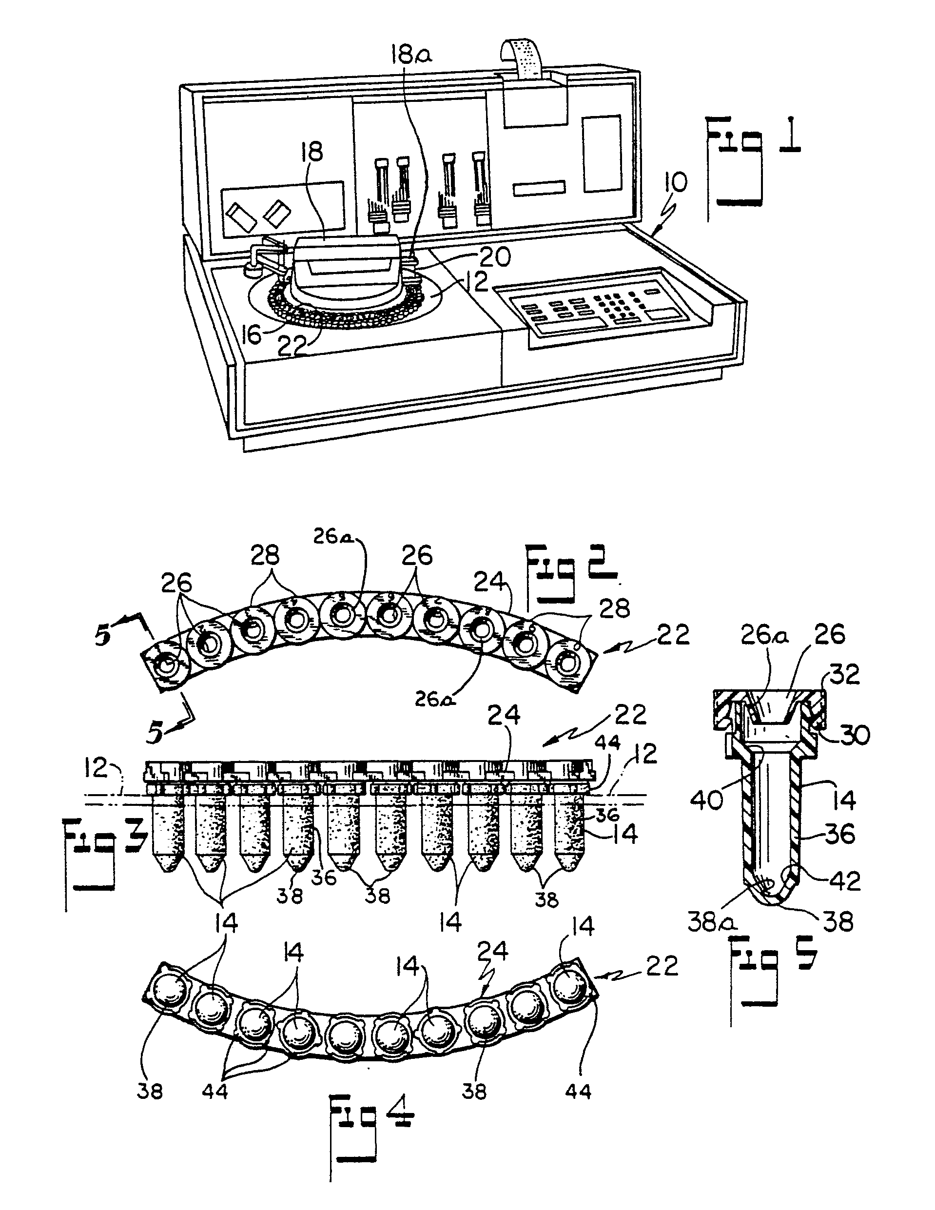
FIGURE 1 is a perspective view of a clinical analyzer apparatus with which the specimen
receptacle assembly of the invention may be used;
FIGURE 2 is a top plan view of the specimen receptacle assembly of the invention;
FIGURE 3 is a front elevational view of the specimen assembly illustrated in Figure
2;
FIGURE 4 is a bottom plan view of the specimen assembly illustrated in Figures 2 and
3;
FIGURE 5 is an enlarged, vertical sectional view taken generally along the plane of
line 5-5 of Figure 2, looking in the direction of the arrows;
FIGURE 6 is a top plan view of the specimen cup per se of the assembly of Figures
2-5;
FIGURE 7 is a vertical sectional view taken generally along the plane of line 7-7
of Figure 6, looking in the direction of the arrows;
FIGURE 8 is an enlarged, fragmentary illustration of the head or upper portion of
the specimen cup of Figures 6 and 7, illustrating in greater detail the interlocking
barbs and associated cam surfaces thereon, for facilitating the assembly and disassembly
of the cup with the strip cap, and for holding the cup in assembled relationship with
the cap;
FIGURE 9 is an enlarged, fragmentary illustration of the cup and cap in assembled
condition;
FIGURE 10 is an enlarged, fragmentary illustration of the cup and cap during assembly
of the cap onto an associated cup, and showing the generally radial inward flexure
of the interlocking barbs on the upper end portion of the cup, due to the application
of the cap to the cup, which permits the entry of the cups into interlocking coaction
with the associated cap;
FIGURE 11 is an enlarged, fragmentary top plan illustration of the cup, and showing
in phantom lines the flexure of the web structure of the upper portion of the cup
during the inward bending or flexure movement of the interlocking barbs of the cup
upon entry into the cap, and upon disassembly of the cup from the cap, to accomplish
the snap-on connection thereof; and
FIGURE 12 isa bottom plan illustration of the cap member of the assembly of Figures
2-5. The apparatus illustrated in Figure 1 is related to the testing of biological
samples such as for instance serum, but the present invention is not restricted to
such type of analyzing. Such analyzer apparatus may be used, for instance, to provide
for automatic testing of individual body fluid samples of a substantial number of
patients suspected of having for example, some disease, such as for instance gonorrhea,
and facilitates mass population screen testing.
[0015] Such apparatus conventionally includes a transport ring 12 which has a plurality
of openings 12a therein disposed in a circular pattern, for receiving for instance,
specimen cups 14 (Figs. 3 and 5) which are supported in such openings and contain
the specimens to be analyzed by the apparatus. In the apparatus illustrated, the inner
ring 16 of vessels are the specimen cups illustrated in connection with the invention.
A rotatable and powered head 18 on the apparatus may include an arm 18a which is movably
transversely with respect to a transport ring 12 and which may include a vertically
movable probe 20 for taking material from the respective serum cup. Apparatus 10 may
be of the general type identified as an Impact 400 Analyzer, produced by the present
applicant. Reference may also be had to U.S. patent 4,236,825 (Saul R. Gilford) for
an example of another type of analyzer which is adapted to perform the same general
operations on specimens, using however, a somewhat different and less sophisticated
mode of operation as compared to the aforementioned Impact 400 Analyzer.
[0016] Figures 2-5 show a cap and cup assembly 22 according to the invention for use in
the analyzer of Figure 1, but it will be understood that this may be used in other
types of analyzers and other apparatus wherein it is an advantage to be able to handle
a plurality of the specimen cup members at one time, instead of individually. Assembly
22 comprises a strip-like cap 24, having a plurality of the aforementioned specimen
cups 14 removably secured thereto, as shown for instance in Figures 2-5. Cap 24 has
a plurality of openings 26 extending therethrough and disposed in generally spaced
relation lengthwise of the cap. The openings may have indicia 28, in this instance
numbers, associated therewith, for identifying the particular specimen cup openings.
Each of the openings 26 is preferably defined by a funnel-like structure 26a extending
downwardly from the top surface of the cap, for a purpose described below.
[0017] Referring in particular to Figure 12 which shows the bottom of the strip cap 24,
there is associated with each of the openings 26 in the cap, means 30 for interlocking
the cups 14 in the strip cap in releasable relationship. Such means 30 provides a
snap-fastening arrangement between the cap 24 and the cups 14.
[0018] Means 30, in the embodiment illustrated, comprises an inwardly extending shoulder
30a circumscribing the respective recess 31 in the cap receiving the upper end of
the respective cup therein, and adapted for interlocking coaction with complementary
fastening means 32 (Figures 9 and 10) on the cups 14, as is described below in greater
detail.
[0019] The strip cap 24 is preferably formed of plastic so that it may be thrown away after
one use thereof, and. a suitable plastic material has been found to be medium impact
ABS plastic. Such plastic material is preferably white for marker readability. The
height H (Figure 10) of the strip cap is such as to provide adequate space for writing
on the exterior side surfaces of the cap by the analyzer operator, and the plastic
material is preferably of such a type that such writing can be accomplished by conventional
writing instruments. Sufficient space is provided on the top surface to provide suitable
indicia for identifying each individual cup, as aforesaid.
[0020] The cups 14 preferably comprise a widened mouth portion 34 (Figure 7) which facilitates
the pouring of a specimen into the cup, an elongate stem of body portion 36 depending
from the mouth portion 34, and a tip portion 38 which preferably has a highly polished
spherical-like interior surface 38a for facilitating the removal of the specimen material
in the cup as by aspiration from the cup, and thus minimizes the amount of residual
fluid when the cup is aspirated, as for instance by the automatic probe 20. The mouth
portion 34 is preferably connected to the stem or body portion 36 by inwardly sloping
surface 40 disposed at an angle of approximately 45° with respect to the horizontal,
with the tip portion 38 being connected to the stem or body portion 36, on its interior
surface, by downwardly and inwardly sloping side wall surfaces 42, as best illustrated
in Figure 7. The cup 14 may have a plurality of circumferentially spaced protrusions
44 thereon, adapted to support the cup in an opening in a support surface, such as
the aforementioned transport ring 12, and to prevent said cup from falling through
any hole in the transport ring 12.
[0021] Each cup is provided at its upper end with the aforementioned interlocking means
32, which in the embodiment illustrated comprise spaced barbs 46, connected with thin
web sections 46a.
[0022] Each of the barbs 46 has a cam surface 48 thereon adapted to camming engagement with
a complementary cam surface 50 (Figures 9 and 10) on the shoulder 30a of cap member
24, so as to cause inward flexing or general radial movement of the barbs during assembly
of the cap onto the cup or vice versa. Aforementioned cam surfaces 48 and 50 preferably
slope at an angle of approximately 15° with respect to the vertical. During such general
-inward movement of the barbs during application of the cap (or the removal of the
cap from the cup) the webs 46a flex or crease so as to permit the barbs 46 on the
cup to pass the shoulder 30a on the cap until the barbs clear the shoulder, at which
time they snap back into their non-deformed positions and into snap-fastening coaction
with the shoulder 30a on the cap, to interlock the cap and the cups together. In such
interlocked conditions, the top of the cap generally has a clearance C (Figure 9)
at top to resist disengagement when bumped sideways and to provide overtravel to ensure
complete installation of all cups. The aforementioned funnel portion 26a, aids in
preventing evaporation of the specimen contained in the respective cup, thus aiding
in preserving the accuracy of the tests run thereon.
[0023] Each barb 46 on the cup preferably has a sloping undersurface 54 (Figure 8) which
is adapted for camming engagement with the sloping surface 56 on the respective shoulder
30 of the cap, so as to provide a directional engagement force, the barbs being thus
easily installed and more difficult to remove. During disengagement, the barbs again
swing or move inwardly against the resistance to creasing or crimping of the webs
46a until the head of the barbs on the cup move past the respective shoulder 30 on
the cap, at which time the barbs swing back to their normal non-deformed position,
as illustrated for instance in Figures 7, 8 and 9. Aforementioned surfaces 54 and
56 preferably slope at an angle of approximately 30° with respect to the horizontal.
[0024] The cups are preferably formed of plastic so that they can be readily thrown away
after one use thereof. A suitable material has been found to be polyethylene plastic,
and a mixture of approximately 25% by weight of high density polyethylene and approximately
75% by weight of low density polyethylene has been found to be particularly suitable
for providing the cups of the invention with the desired flexibility. However, it
will be understood that other mixtures and types of plastic materials may also be
used.
[0025] The interlocking coaction between the shoulder means 30 on the cap with the interlocking
means 32 on the cups, provides a sufficient connection to support the axial load of
the specimen material disposed in the cups, and is such as preferably to provide for
a minimum holding power of approximately 185 g (6.5 ounce) axial load on the respective
cup. Such as arrangement provides for the maintenance of the assembly of the cap and
the cups for the purpose to which they are adapted for use, and yet provides for ready
separation of the cups from the cap or vice versa, when that is deemed desirable or
necessary.
[0026] The rounded exterior configuration of the end tip of the cups facilitates the entry
of the cap-cup assembly into the receiving openings in support plate, such as for
instance the aforementioned transport plate 12 of the analyzer apparatus.
1. A specimen cup and cap assembly (22) for a clinical analyzer apparatus (10), comprising
a strip-like cap (24) having a plurality of generally vertically extending spaced
openings (26) therethrough, a plurality of separate specimen cups (14), and means
(30; 32) on said cap (24) and on each said cups (14) for releasably attaching said
cups (14) to said cap (24) as an assembly, whereby each of said openings (26) provide
access from the exterior to the interior of a respective one said cups (14), said
openings (26) being adapted to provide access for an automatic probe (20) of the clinical
analyzer apparatus (10).
2. An assembly in accordance with claim 1, wherein said cap (24) is formed as an arcuate
strip segment, in plan, said plurality of openings (26) therethrough being spaced
lengthwise of said cap segment and in generally evenly spaced relation between the
sides thereof.
3. An assembly in accordance with claim 1 or 2, wherein each of said cups (14) has
an upper portion comprising said attaching means (32) and possessing general flexibility
so that said cup (14) can be snapped into and out of holding coaction with said cap
(24) upon respectively upward and downward or sidewise force applied to said cup (14).
4. An assembly in accordance with claim 3, wherein said upper portion of said cup
(14) is formed of polyethylene plastic, said upper portion possessing memory but being
deformable generally radially inwardly to permit said snap fastening entry and/or
removal of said cup (14) from said cap (24) or vice versa.
5. An assembly in accordance with claim 3 or 4, wherein said attaching means (32)
on said cup (14) includes an interlock surface (54) disposed at an angle of approximately
30° with respect to the horizontal and which diverges in a downward and inward direction,
said cap (24) having a complementarily arranged interlock surface (56) adapted for
surface-to-surface engagement with said interlock surface (54) on said cup (14).
6. An assembly in accordance with claim 3, 4 or 5, wherein said attaching means (32)
on said cup (14) comprises a plurality of peripherally spaced projections (46) thereon,
each of which has cam means (48) adapted for camming coaction with generally complementary
cam means (50) on said cap (24) for causing said inward deformation of said upper
portion of said cup (14) with respect to said cap (24) and entry of said cup (14)
into snapped fastened coaction relation with said cap (24).
7. An assembly in accordance with claim 6, wherein said projections (46) are connected
by flexible webs (46a), the complementary cam means (50) on the cap being adapted
for camming coaction with said cam means (48) on said cup (14) such as to force the
cam means (48) on said cup (14) generally radially inwardly to cause generally radial
folding of said webs (46a) until said cam means (50, 48) on said cap (24) and said
cup (14) pass one another at which time said webs (46a) and cam means (48) on said
cup (14) are adapted to spring back into their original orientation to cause said
attaching means (32) to interlock said cup (14) with said cap (24).
8. An assembly in accordance with claim 7, wherein said cam means (48) on said upper
portion of said cup (14) is disposed at an angle of approximately 15 degrees with
respect to the vertical and slopes in a direction upwardly and inwardly toward the
axis of said cup (14), and wherein said cam means (50) on said cap (24) is disposed
at an angle of approximately 15 degrees with respect to the vertical and extends in
an upward and inward direction from the horizontal.
9. An assembly in accordance with any preceding claim, wherein said cap (24) is formed
of medium impact ABS plastic.
10. An assembly in accordance with any preceding claim, including laterally projecting
protrusions (44) on each of said cups (14) intermediate the upper and lower extremities
of said cup, adapted for engagement with a support ring (12) of the apparatus (10).
11. An assembly in accordance with any preceding claim including indicia (28) on said
cap (24) for identifying the openings (26) in said cap (24) with a particular specimen
placed therein.
12. An assembly in accordance with any preceding claim, wherein each of said cups
(14) comprises a widened mouth portion (34) at its upper end which can be conveniently
poured into, and a narrower stem portion (36) depending from said mouth portion (34).
13. An assembly in accordance with claim 12, wherein the juncture of said mouth portion
(34) with said stem portion (36) is defined by a sloping surface (40) extending in
converging relationship in a downward direction.
14. An assembly in accordance with any preceding claim, wherein the lower tip portion
(38) of each of said cups (14) comprises a highly polished spherical interior surface
(38a) at its extremity to facilitate the removal of solution from the respective cup
(14) by aspiration.
15. An assembly in accordance with claim 14, wherein the exterior end of said tip
portion is of convergingly tapered configuration in a downward direction.
16. A specimen cup (14) adapted for assembly with a cap (24) for use in a clinical
analyzer apparatus (10), said cup (14) comprising an upper portion possessing general
flexibility so that said cup (14) can be snapped into and out of holding coaction
with an associated cap (24) upon respectively upward and downward force applied to
said cup (14) with respect to said cap, said upper portion comprising attaching and
cam means (32, 48) spaced circumferentially about the periphery of said cup at the
upper end thereof, and being so constructed and arranged that said attaching and cam
means (32, 48) can flex generally radially inwardly upon either upward movement of
said cup (14) with respect to an associated cap (24) or upon downward movement of
the associated cap (24) with respect to said cup (14), for causing interlocking coaction
between said attaching and cam means on said cup (32, 48) and complementary attaching
and cam means (30, 50) on the cap (24).
17. A cup in accordance with claim 16, wherein said attaching and cam means (32, 48)
comprises spaced projection (46) spaced about the periphery of said cup (14) and connected
by flexible webs (46a) so that upon insertion and/or removal of said cup (14) from
the cap (24), the projections (46) are caused to move generally radially inwardly
and to cause flexure to said webs (46a), to permit the attaching and cam means (32,
48; 30, 50) on the cup (14) and the cap (24) to pass by one another, after which said
attaching and cam means (32, 48) on said cup (14) spring back into non-deformed condition.
18. A cup in accordance with claim 16 or 17, said cup (14) comprising a stem portion
(36) extending downwardly from said upper portion, and including means (44) projecting
laterally of said stem portion (36) for engagement with an apertured support (12)
in which the cup (14) is adapted to be mounted in the analyzer apparatus (10).
19. A cup in accordance with claim 16 or 17, which comprises an upper mouth portion
(34), a stem portion (36) depending from the mouth portion (34), and a lower tip portion
(38) extending downwardly from said stem portion (36), said cup (14) being of a generally
circular configuration in horizontal cross-section with said mouth portion (34) being
of a greater diameter as compared to the diameter of said stem portion (36), and with
said tip portion (38) have a spherical interior surface (38a) with the centre of the
spherical surface being disposed in a plane extending through the lower extremity
of said stem portion (36).
20. A cup in accordance with claim 19, wherein the radius of said spherical surface
(38a) is less than the radius of said stem portion (36), and wherein said mouth portion
(34) is connected to said stem portion to define the recess in said cup (14) by a
downwardly sloping shoulder portion (40) disposed at an angle of approximately 45°
with respect to the horizontal.
21. A cup in accordance with any one of claims 16 to 20, which is formed of a mixture
of high density and low density polyethylene thereby providing flexibility to the
cup.
22. A cup in accordance with claim 21, wherein the polyethylene material for the cup
comprises twenty-five percent by weight of high density polyethylene and seventy-five
percent by weight of the low density polyethylene.
23. A cap adapted for assembly with a plurality of specimen cups for use for instance
in a clinical analyzer apparatus, said cup (24) comprising an arcuate strip of material
having a plurality of generally vertically extending openings (26) therethrough, and
means (30) on the underside of said cap (24) for releasably attaching a plurality
of associated cups (14) to the cap (24) as an assembly, said means (30) coacting with
each of said openings (26) for orientating a respective cup (14) in communicating
relation with the respective one of said openings (26) in said cap (24) from exterior
of said cap (24).
24. A cap in accordance with claim 23, wherein each of said openings (26) is defined
by an inverted truncated conical portion (26a), and said means (30) comprises a shoulder
(30a) coacting with the respective opening (26) adapted for interlocking an associated
cup (14) to the underside of the cap (24).
25. A cap in accordance with claim 24, formed of opaque plastic material, said cap
(24) having a defining exterior side wall depending below said conical portions (26a)
defining said openings therethrough, said plastic being able to be written upon by
conventional writing instruments.
1. Probengefäß- und Deckelaufbau (22) für einen klinischen Analyseapparat (10) gekennzeichnet
durch einen streifenähnlichen Deckel (24) mit einer Vielzahl von sich im wesentlichen
vertikal erstreckenden beabstandeten Öffnungen (26) durch diesen, eine Vielzahl von
separaten Probengefäßen (14) und eine Einrichtung (30; 32) an dem Deckel (24) und
an jedem der Gefäbe (14) für das lösbare Anbringen der Gefäße (14) an dem Deckel (24)
als eine Gesamtheit, wobei jede der o Öffnungen (26) einen Zugang von der Außenseite
zu dem Inneren von jeweils einem der Gefäße (14) vorsieht, und wobei die Öffnungen
(26) für den Zugang einer automatischen Sonde (20) des klinischen Analyseapparates
(10) ausgebildet sind.
2. Aufbau nach Anspruch 1, dadurch gekennzeichnet, daß der Deckel (24) als eine bogenförmiges
Streifensegment ausgebildet ist, wobei die Vielzahl der Öffnungen (26) durch dieses
in der Anordnung in Längsrichtung des Deckelsegments und im allgemeinen gleichmäßig
zwischen dessen Seiten beabstandet sind.
3. Aufbau nach Anspruch 1 oder 2, dadurch gekennzeichnet, daß jedes Gefäß (14) einen
oberen Abschnitt besitzt, der die Befestigungseinrichtung (32) aufweist, und der eine
derartige allgemeine Flexibilität besitzt, daß das Gefäß (14) in ein und aus ein haltendes
Zusammenwirken mit dem Deckel (24) jeweils bei aufwärts und abwärts oder seitwärts
gerichteter Kraft, die auf das Gefäß (14) ausgeübt wird, eingerastet werden kann.
4. Aufbau nach Anspruch 3, dadurch gekennzeichnet, daß der obere Abschnitt des Gefäßes
(14) aus Polyethylenkunststoff gebildet ist, wobei der obere Abschnitt Formerinnerungsvermögen
besitzt, aber im allgemeinen radial nach innen verformbar ist, um den Eintritt der
Schnappbefestigung und/oder das Entfernen des Gefäßes (14) von dem Deckel (24) oder
umgekehrt zu ermöglichen.
5. Aufbau nach Anspruch 3 oder 4, dadurch gekennzeichnet, daß die Befestigungseinrichtung
(32) an dem Gefäß (14) eine Verriegelungsfläche (54) aufweist, die in einem Winkel
von etwa 30° bezüglich der Waagerechten angeordnet ist und die in einen runden und
nach innen weisenden Richtung auseinanderläuft, wobei der Deckel (24) eine in komplementärer
Weise angeordnete Regelungsfläche (56) besitzt, die für eine flächige Anlage an der
Verriegelungsfläche (54) an dem Deckel (14) ausgebildet ist.
6. Aufbau nach Anspruch 3, 4 oder 5, dadurch gekennzeichnet, daß die Befestigungseinrichtung
(32) an dem Gefäß (14) eine Vielzahl von in Umfangsrichtung auf diesem beabstandete
Ansätze (46) aufweist, von denen jeder eine Führungseinrichtung (48) für das führende
Zusammenwirken mit einer im wesentlichen komplementären Führungseinrichtung (50) an
dem Deckel (24) besitzt, um die nach innen gerichtete Verformung des oberen Abschnitts
des Gefäßes (14) bezügliche des Deckels (24) und den Eintritt des Gefäßes (14) in
die eingeschnappte befestigte Zusammenwirkungszuordnung mit dem Deckel (24) zu veranlassen.
7. Aufbau nach Anspruch 6, dadurch gekennzeichnet, daß die Ansätze (16) mittels flexibler
Stege (46a) verbunden sind, wobei die komplementäre Führungseinrichtung (50) an dem
Deckel für das führende Zusammenwirken mit der Führungseinrichtung (48) an dem Gefäß
(14) derart ausgebildet ist, daß sie die Führungseinrichtung (48) an dem Gefäß (14)
im allgemeinen radial nach innen drückt, um ein im allgemeinen radiales Falten der
Stege (46a) zu veranlassen, bis die Führungseinrichtungen (50, 48) an dem Deckel (24)
und an dem Gefäß (14) aneinander vorbeitreten, wobei zu dieser Zeit die Stege (46a)
und die Führungseinrichtung (48) an dem Gefäß (14) in ihre ursprüngliche Orientierung
zurückzuspringen vermögen, damit die Befestigungseinrichtung (32) das Gefäß (14) mit
dem Deckel (24) verriegelt.
8. Aufbau nach Anspruch 7, dadurch gekennzeichnet, daß die Führungseinrichtung (48)
an dem oberen Abschnitt des Gefäßes (14) unter einem Winkel von etwa 15° bezüglich
der vertikalen Richtung angeordnet ist und in einer Richtung nach oben und nach innen
zu der Achse des Gefäßes (14) schräg abfällt, und daß die Führungseinrichtung (50)
an dem Deckel (24) unter einem Winkel von etwa 15° bezuglich der Senkrechten angeordnet
ist und sich in einer nach oben und nach innen weisenden Richtung aus der Horizontalen
erstreckt.
9. Aufbau nach einem vorangehenden Anspruch, dadurch gekennzeichnet, daß der Deckel
(24) aus einem ABS-Kunstharz mittlerer Schlagfestigkeit (medium impact ABS plastic)
gebildet ist.
10. Aufbau nach einem vorangehenden Anspruch, gekennzeichnet durch seitlich vorstehenden
Vorsprünge (44) an jedem Gefäß (14) zwischen dem oberen und dem unteren Ende des Gefäßes,
die für das Angreifen an einem Haltering (12) des Apparates (10) ausgebildet sind.
11. Aufbau nach einem vorangehenden Anspruch, gekennzeichnet durch Anhaltszahlen (28)
auf dem Deckel (24) für das Identifizieren der Öffnungen (26) in dem Deckel (24) mit
einer besonderen Probe, die darin angeordnet ist.
12. Aufbau nach einem vorangehenden Anspruch, dadurch gekennzeichnet, daß jedes Gefäß
(14) einen ausgeweiteten Mündungsabschnitt (34) an seinem oberen Ende, in den in üblicher
Weise eingegossen werden kann, und einen engeren Schaftabschnitt (36) aufweist, der
von dem Mündungsabschnitt (34) nach unten weist.
13. Aufbau nach Anspruch 12, dadurch gekennzeichnet, daß die Verbindungsstelle des
Mündungsabschnitts (34) mit dem Schaftabschnitt (36) durch eine geneigte Fläche (40)
gebildet ist, die sich in konvergierender Zuordnung in einer nach unten weisenden
Richtung erstreckt.
14. Aufbau nach einem vorangehenden Anspruch, dadurch gekennzeichnet, daß der untere
Endabschnitt (38) jedes Gefäßes (14) eine hochpolierte sphärische Innenfläche (38a)
an seinem äußersten Ende aufweist, um das entfernen von Lösung aus dem jeweiligen
Gefäß (14) durch Ansaugen zu erleichtern.
15. Aufbau nach Anspruch 14, dadurch gekennzeichnet, daß das äußere Ende des Endabschnitts
in nach unten weisender Richtung eine konvergente chronisch zulaufende Ausbildung
aufweist.
16. Probengefäß (14) für das Zusammensetzen mit einem Deckel (24) zur Verwendung bei
einem klinische Analyseapparat (10), wobei das Gefäß (14) gekennzeichnet ist durch
einen oberen Abschnitt, der eine allgemeine Flexibilität in der Weise besitzt, daß
das Gefäß (14) in ein und aus ein haltendes Zusammenwirken mit einem zugeordneten
Deckel (14) bei jeweils nach oben und nach unten gerichteter Kraft, die auf das Gefäß
(14) bezüglich des Deckels ausgeübt wird, eingerastet werden kann, wobei der obere
Abschnitt eine Befestigungs- und Führungseinrichtung (32, 48) aufweist, die rings
um den Umfang des Gefäbes an dessen oberen Ende beabstandet und so ausgebildet und
angeordnet ist, daß die Befestigungs- und Führungseinrichtung (32, 48) sich im allgemeinen
radial nach innen entweder bei einer Aufwärtsbewegung des Gefäßes (14) bezüglich eines
zugeordneten Deckels (24) oder einer Abwärtsbewegung des zugeordneten Deckels (24)
bezüglich des Gefäßes (14) biegen kann, um ein verriegelndes Zusammenwirken zwischen
der Befestigungs- und Führungseinrichtung (32, 48) an dem Gefäß und der komplementären
Befestigungs- und Führungseinrichtung (30, 50) an dem Deckel (24) zu veranlassen.
17. Gefäß nach Anspruch 16, dadurch gekennzeichnet, daß die Befestigungs- und Führungseinrichtung
(32, 48) beabstandete Ansätze (46) besitzt, die derart um den Umfang des Gefäßes (14)
beabstandet und durch flexible Stege (46a) verbunden sind, daß beim Einsetzen und/oder
Entfernen des Gefäßes (14) von dem Deckel (24) die Ansätze (46) veranlaßt werden,
sich allgemein radial nach innen zu bewegen und das Biegen der Stege (46a) zu verursachen,
um das Passieren der Befestigungs- und Führungseinrichtungen (32, 48; 30, 50) an dem
Gefäß (14) und an dem Deckel (24) aneinander zu ermöglichen, wonach die Be- - festigungs-
und Führungseinrichtung (32, 48) an dem Gefäß (14) in den nicht deformierten Zustand
zurückspringt.
18. Gefäß nach Anspruch 16 oder 17, dadurch gekennzeichnet, daß das Gefäß (14) einen
Schaftabschnitt (36) besitzt, der sich von dem oberen Abschnitt nach unten erstreckt,
und eine Einrichtung (44) aufweist, die seitlich von dem Schaftabschnitt (36) für
den Eingriff in einen mit Löchern versehenen Halter (12) vorstehen, in dem das Gefäß
(14) in dem Analyseapparat montierbar ist.
19. Gefäß nach Anspruch 16 oder 17, gekennzeichnet durch einen oberen Mündungsabschnitt
(34), einen Schaftabschnitt (36), der von dem Mündungsabschnitt (34) nach unten weist,
und einem unteren Endabschnitt (38), der sich von dem Schaftabschnitt (36) nach unten
erstreckt, wobei das Gefäß (14) im Horizontalschnitt eine allgemein kreisförmige Gestaltung
besitzt, wobei der Mündungsabschnitt (34) einen größeren Durchmesser im Vergleich
zu dem Durchmesser des Schaftabschnitts (36) aufweist, und wobei der Endabschnitt
(38) eine sphärische Innenfläche (38a) besitzt, wobei die Mitte der sphärischen Fläche
in einer Ebene angeordnet ist, die sich durch das untere Ende des Schaftabschnitts
(36) erstreckt.
20. Gefäß nach Anspruch 19, dadurch gekennzeichnet, daß der Radius der sphärischen
Fläche (38a) kleiner als der Radius des Schaftabschnitts (36) ist, und daß der Mündungsabschnitt
(34) mit dem Schaftabschnitt verbunden ist, um den Absatz in dem Gefäß (14) mittels
eines nach unten geneigten Schulterabschnitts (40) zu bilden, der unter einem Winkel
von etwa 45° bezüglich der Horizontalen angeordnet ist.
21. Gefäß nach einem der Ansprüche 16-20, gekennzeichnet durch die Herstellung aus
einem Gemisch aus hochverdichtetem und niedrigverdichtetem Polyethylen, um dadurch
die Flexibilität für das Gefäß zu schaffen.
22. Gefäß nach Anspruch 21, dadurch gekennzeichnet, daß das Polyethylenmaterial für
das Gefäß 25 Gew.-% an hochverdichtetem Polyethylen und 25 Gew.-% an niedrigverdichtetem
Polyethylen aufweist.
23. Deckel zum Zusammensetzen mit einer Vielzahl von Probengefäßen zur Verwendung
beispielsweise in einem klinischen Analyseapparat, dadurch gekennzeichnet, daß der
Deckel (24) aus einem gebogenen Materialstreifen besteht, der zahlreiche sich vertikal
erstreckende Öffnungen (26) durch diesen besitzt, und daß eine Einrichtung (30) an
der Unterseite des Deckels (24) vorgesehen ist, um lösbar eine Vielzahl von zugeordneten
Gefäßen (14) an dem Deckel (24) als Gesamtheit zu befestigen, wobei die Einrichtung
(30) mit jeder der Öffnungen (26) in Berührung steht, um ein jeweiliges Gefäß (14)
in kommunizierender Zuordnung mit der jeweiligen Öffnung (26) in dem Deckel (24) von
der Außenseite des Dekkels (24) zu orientieren.
24. Deckel nach Anspruch 23, dadurch gekennzeichnet, daß jede der Öffnungen (26) durch
einen umgekehrten abgeschnittenen konischen Abschnitt (26a) gebildet ist, und daß
die Einrichtung (30) eine mit der jeweiligen Öffnung (26) zusammenwirkende Schulter
(30a), aufweist, durch die ein zugeordnetes Gefäß (14) an der Unterseite des Deckels
(24) verriegelbar ist.
25. Deckel nach Anspruch 24 aus einem opaken Kunststoffmaterial, dadurch gekennzeichnet,
daß der Deckel (24) eine begrenzende Außenseitenwand besitzt, die unterhalb der konischen
Abschnitte (26a) herabreicht, durch welche die Öffnungen gebildet sind, wobei das
Kunststoff mit üblichen Schreibinstrumenten beschreibbar ist.
1. Ensemble (22) de tubes à échantillon avec couvercle, pour un appareil d'analyse
clinique (10), comprenant un couvercle en forme de bande (24) traversé par une pluralité
d'ouvertures (26) s'étendant verticalement dans leur ensemble, une pluralité de tubes
à échantillon (14) et des moyens (30, 32) prévus sur ledit couvercle (24) et sur chacun
desdits tubes (14) pour fixer ces derniers sur ledit couvercle (24) de façon amovible
pour former un ensemble, de telle façon que chacune desdites ouvertures (26) procure
un accès de l'extérieur vers l'intérieur du tube (24) correspondant, ces ouvertures
(26) étant adaptées à procurer un accès pour une sonde automatique (20) de l'appareil
d'analyse clinique (10).
2. Ensemble selon la revendication 1, dans lequel ledit couvercle (24) a la forme,
en plan, d'un arc de cercle, lesdites ouvertures (26) qui le traversent étant espacées
le long de cet arc de cercle et sensiblement à égale distance de ses bords.
3. Ensemble selon la revendication 1 ou 2, dans lequel chacun desdits tubes (14) comprend
une partie supérieure comportant lesdits moyens de fixation (32) et présente une flexibilité
d'ensemble telle que ledit tube (14) peut être emboîté dans ledit couvercle (24) et
en être déboîté sous l'action de forces appliquées audit tube (14) et dirigé respectivement
vers le haut et vers la bas ou latéralement.
4. Ensemble selon la revendication 3, dans lequel ladite partie supérieure dudit tube
(14) est en polyéthylène plastique, ayant une mémoire, mais est déformable radialement
vers l'intérieur pour permettre ladite fixation par emboîtement et/ou le déboîtement,
et vice-versa.
5. Ensemble selon la revendication 3 ou 4, dans lequel lesdits moyens de fixation
(32) prévus sur le tube (14) comprennent une surface d'enclenchement (54) fais ant
à peu près 30° avec l'horizontale et dirigée vers le bas et vers l'intérieur, le couvercle
(24) portant une surface d'enclenchement complémentaire (56) disposée pour coopérer
par un engagement surface- contre-surface avec ladite surface d'enclenchement (54)
du tube (14).
6. Ensemble selon l'une des revendications 3 à 5, dans lequel lesdits moyens de fixation
(32) du tube (14) comprennent une série de saillies (46) écartées le long de sa périphérie,
et pourvues chacune d'une came (48) destinée à coopérer par effet de came avec une
came complémentaire (50) prévue sur le couvercle (24), pour procurer ladite déformation
vers l'intérieur de la partie supérieure du tube (14) par rapport au couvercle (24)
et amener ledit tube en relation d'enclenchement avec le couvercle.
7. Ensemble selon la revendication 6, dans lequel lesdites saillies (46) sont reliées
entre elles par des voiles flexibles (46a), les cames complémentaires (50) du couvercle
étant adaptées pour coopérer avec lesdites cames (48) du tube (14) de telle façon
qu'elles poussent les cames (48) du tube radialement vers l'intérieur en pliant radialement
lesdites voiles (46a) jusqu'à ce que lesdites cames (50, 48) du couvercle (24) et
du tube (14) passent l'une sur l'autre, lesdites voiles (46a) et cames (48) du tube
revenant élastiquement en arrière à ce moment pour reprendre leur orientation initiale
et provoquer l'enclenchement du tube (14) avec le couvercle grâce aux moyens de fixation
(32).
8. Ensemble selon la revendication 7, dans lequel ladite came (48) de la partie supérieure
du tube (14) fait un angle d'environ 15° avec la verticale étant dirigée vers le haut
et vers l'intérieur, en direction de l'axe du tube (14), et ladite came (50) du couvercle
(24) fait un angle d'environ 15° avec la verticale et est dirigée vers le haut et
vers l'intérieur.
9. Ensemble selon l'une des revendications précédentes, dans lequel ledit couvercle
(24) est en ABS de résistance moyenne au choc.
10. Ensemble selon l'une des revendications précédentes, comportant des saillies latérales
(44) sur chaque tube, entre ses extrémités supérieure ou inférieure, destinées à coopérer
avec un anneau de support (12) de l'appareil (10).
11. Ensemble selon l'une des revendications précédentes, comportant des repères (28)
sur le couvercle (24) pour indentifier les ouvertures (26) dudit couvercle avec l'échantillon
particulier qui y est placé.
12. Ensemble selon l'une des revendications précédentes, dans lequel chaque tube (14)
a une partie d'embouchure (34) élargie, et une partie de queue (36) plus étroite,
au-dessous de la partie d'embouchure.
13. Ensemble selon la revendication 12, dans lequel la jonction entre les parties
d'embouchure (34) et de queue (36) est constituée par une surface inclinée (40) convergente
vers le bas.
14. Ensemble selon l'une des revendications précédentes, dans lequel la partie de
fond (38) de chaque tube (14) présente une surface intérieure sphérique finement polie
(38a) à son extrémité pour faciliter l'enlèvement d'une solution dudit tube 14 par
aspiration.
15. Ensemble selon la revendication 14, dans lequel l'extérieur de l'extrémité de
ladite partie de fond a une forme biseautée, convergente vers le bas.
16. Tube à échantillon (14) destiné à être monté sur un couvercle (24) pour être utilisé
dans un appareil d'analyse clinique (10) et comprenant une partie supérieure ayant
une flexibilité d'ensemble telle que ledit tube (14) peut être emboîté sur un couvercle
associée (24) et en être déboîté sous l'effet d'une force appliquée audit tube respectivement
vers le haut et vers le bas, ladite partie supérieure comprenant des moyens de fixation
et des cames (32, 48) écartés circonfé- rentiellement sur la périphérie dudit tube
à son extrémité supérieure, et étant conçue de telle façon que lesdits moyens de fixation
et cames (32, 48) peuvent fléchir radialement vers l'intérieure sous l'effet d'un
déplacement vers le haut dudit tube (14) par rapport audit couvercle (24), ou vers
le bas dudit couvercle par rapport audit tube, afin de provoquer une coopération d'enclenchement
entre lesdits moyens de fixation et cames (32, 48) du tube et des moyens de fixation
et cames complémentaires (30, 50) dudit couvercle.
17. Tube selon la revendication 16, dans lequel lesdits moyens de fixation et cames
(32, 48) comprennent des saillies (46) écartées le long de la périphérie du tube et
reliées entre elles par des voiles flexibles (46a), de telle façon que, lors de la
fixation du tube (14) sur le couvercle (24) ou son enlèvement, les saillies (46) sont
forcées à se déplacer radialement vers l'intérieur et obliger lesdits voiles (46a)
à fléchir afin de permettre aux moyens de fixation et cames (32, 48; 30, 50) du tube
(14) et du couvercle (24) de passer l'un sur l'autre, après quoi lesdits moyens de
fixation et cames (32, 48) du tube reviennent élastiquement en arrière pour reprendre
leur étant initial.
18. Tube selon la revendication 16 ou 17, et comprenant une partie de queue (36) s'étendant
vers le bas à partir de la partie supérieure, et comportant des moyens (44) faisant
saillie latéralement sur ladite partie de queue, et destinés à coopérer avec un support
(12) pourvu d'ouvertures, et auquel le tube est adapté en vue d'être monté dans un
appareil d'analyse (10).
19. Tube selon la revendication 16 ou 17, comprenant une partie supérieure d'embouchure
(34), une partie de queue (36) au-dessous de la partie d'embouchure, et une partie
de fond inférieur (38) s'étendant vers le bas par rapport à la partie de queue (34),
ledit tube ayant une forme générale circulaire en section horizontale, la partie d'embouchure
(34) étant de diamètre supérieur à celui de la partie de queue (36), et la partie
de fond (38) ayant une surface intérieure (38a) sphérique, le centre de la sphère
étant dans un plan passant par l'extrémité inférieure de ladite partie de queue.
20. Tube selon la revendication 19, dans lequel le rayon de ladite surface sphérique
(38a) est inférieur à celui de la partie de queue, et dans lequel la partie d'embouchure
(34) se raccorde à la partie de queue (34) par un épaulement (40) à surface inclinée
d'environ 45° avec l'horizontale.
21. Tube selon l'une des revendications 16 à 20, et constitué d'un mélange de polyéthylène
haute et basse densité, qui procure la fiexibilité du tube.
22. Tube selon la revendication 21, dans lequel le polyéthylène est formé de 25 %
de polyéthylène haute densité et 75 % de polyéthylène basse densité.
23. Couvercle (24) destinée à former un ensemble avec plusieurs tubes à échantillon
pour usage, par exemple, dans un appareil d'analyse clinique, et comprenant une bande
en forme d'arc de cercle traversée par une série d'ouvertures (26) verticales dans
l'ensemble, et comportant, sur sa face inférieure, des moyens (30) pour fixer, de
façon amovible, sur ledit couvercle, une série de tubes associées (14), afin de constituer
un ensemble, lesdits moyens (30) coopérant avec chaque ouverture (26) pour orienter
le tube (14) correspondant pour le mettre en communication avec l'extérieure à travers
ladite ouverture.
24. Couvercle selon la revendication 23, dans lequel chaque ouverture (26) est limitée
par une partie en tronc de cône inversé (26a), et lesdits moyens (30) comprennent
un épaulement (30a) coopérant avec ladite ouverture correspondante (26) pour enclencher
le tube (14) associée sur la face inférieure du couvercle.
25. Couvercle selon la revendication 24, en matière plastique opaque, et comportant
une paroi extérieure descendant au-dessous desdites parties tronconiques (26a) limitant
les ouvertures
(26), ladite matière plastique étant telle qu'on peut écrire sur elle avec des moyens
d'écriture usuels.