| (19) |
 |
|
(11) |
EP 0 014 072 B2 |
| (12) |
NEW EUROPEAN PATENT SPECIFICATION |
| (45) |
Date of publication and mentionof the opposition decision: |
|
18.03.1987 Bulletin 1987/12 |
| (45) |
Mention of the grant of the patent: |
|
11.05.1983 Bulletin 1983/19 |
| (22) |
Date of filing: 16.01.1980 |
|
|
| (54) |
Viscous fan drive
Flüssigkeitsreibungsantrieb eines Ventilators
Transmission à fluide visqueux d'un ventilateur
|
| (84) |
Designated Contracting States: |
|
DE GB |
| (30) |
Priority: |
17.01.1979 US 4095
|
| (43) |
Date of publication of application: |
|
06.08.1980 Bulletin 1980/16 |
| (71) |
Applicant: EATON CORPORATION |
|
Cleveland
Ohio 44114 (US) |
|
| (72) |
Inventor: |
|
- Bridge, Erland Thomas
Marshall, Michigan 49068 (US)
|
| (74) |
Representative: Wright, Peter David John et al |
|
Willowbrook
Winkfield Row
GB-Bracknell, Berkshire RG42 6LS
GB-Bracknell, Berkshire RG42 6LS (GB) |
|
| |
|
[0001] This invention concerns a viscous fluid drive.
[0002] Temperature responsive viscous drives are used to drive engine cooling fans on automotive
vehicles. These drives have a disengaged mode at which the fan is rotated at a relatively
low angular velocity and an engaged mode at which the angular velocity is relatively
high. For fuel conservation and noise reduction, it is preferred to have the disengaged
mode at as low an angular velocity as possible. When a temperature responsive drive
is left in a non-operating vehicle for a period of time, viscous fluid within the
drive fills both the reservoir and the working chamber. Upon start- up of the vehicle's
engine, the water in the radiator is usually relatively cool and, accordingly, operation
of the fan is not required. It is, therefore, desirable to have the fluid pumped out
of the working chamber into the reservoir as quickly as possible in order to reduce
the fan's angular velocity and, accordingly, the noise created by the fan. During
the engaged mode of the drive, it is desirable to keep the fan operating at a relatively
high angular velocity relative to engine angular velocity in order to achieve maximum
cooling. In the event that the pumping element of the drive is too efficient, most
of the fluid within the working chamber will be pumped into the reservoir during relatively
high angular velocities of the engine. This will result in the phenomena commonly
referred to as "high speed pump out" causing the fan speed to be reduced.
[0003] A viscous fluid drive having a rotatable clutch member located in a working chamber
within a rotatable housing member, apertures in a radial wall of the housing member
through which fluid can enter and leave the chamber, and a fixed pumping device located
in the housing member for directing fluid out of the outlet aperture during relative
rotation of the members is known from, for example, U.S. Patent No. 3990556 and W.
German Specification No. 27 23 429. In each case, the pumping device comprises a flat
element mounted on the radial wall adjacent the outlet aperture and thus lying entirely
in a radial plane. A circumferentially extending recess in the element of W. German
Specification No. 27 23 429 serves to direct fluid into the outlet aperture.
[0004] US-A-4133417 discloses a generally similar viscous fluid drive in which a plug straddles
the margin of the rotatable clutch member and serves to pump viscous fluid from annular
spaces which lie on opposite sides of the margin of the clutch member. A front face
of the plug defines a passageway across the periphery of the clutch member through
which the fluid from the space on one side can flow to the other side, from where
it can leave through an outlet.
[0005] The present invention provides, according to one aspect, a viscous fluid drive having
a rotatable clutch member (16) located in a working chamber (22) within a rotatable
housing member (18), an aperture (72) through which working fluid can leave the working
chamber, the aperture being in a radially extending wall (26) of the housing member
and facing a radially extending surface (74) of the clutch member, and a fixed means
(64) in said housing member for directing fluid out through the aperture during relative
rotation of the members, said fixed means (64) comprising a portion (78) in register
with the aperture in the radial direction, and partly obstructing the space between
said radially extending wall and radially extending surface characterised in that
said fixed means (64) has a portion (76) which is in generally the same peripheral
position as the portion (78) and which at least partly obstructs and forms a constriction
in the space between the peripheral inner cylindrical surface (54) of the housing
member and the peripheral outer cylindrical surface (52) of the clutch member at a
position in the peripheral direction, adjacent to said aperture.
[0006] Such a viscous drive will have a relatively low angular velocity in the disengaged
mode, a relatively high angular velocity in the engaged mode without a high speed
pump out, and a relatively short pump out time.
[0007] The preferred embodiment of the present disclosure provides such a drive using components
and assembly techniques that are currently being used on standard viscous drives that
do not possess the characteristics of the invention.
[0008] This embodiment features a temperature responsive viscous fluid drive having a relatively
large clearance between the outer peripheral surface of the clutch member and the
inner peripheral surface of the housing member, and a generally L shaped pumping element
within the working chamber having a radially extending portion secured to the valve
plate and an axially extending portion extending at least across a portion of the
space between the two peripheral surfaces. An outlet opening within the valve plate
is aligned with the pumping element to direct fluid from the working chamber.
[0009] The invention is described further, by way of example, with reference to the accompanying
drawings, in which:-
Fig. 1 is a fragmentary side elevation view in section of a temperature responsive
viscous fluid fan drive according to the disclosure.
Fig. 2 is an enlarged side elevational view of a pumping element according to the
disclosure showing its alignment with the outlet opening.
Fig. 2a is a side elevational view similar to Fig. 2 of another embodiment of a pumping
element.
Fig. 3 is a side view of Fig. 2 or Fig. 2a;
Fig. 4 is a top view of Fig. 2 or Fig. 2a.
Fig. 5 is an enlarged view of a portion of the drive of Fig. 1 taken along another
section line.
Figs. 6 and 7 are similar to Figs. 2 and 4 and illustrating another embodiment of
the invention.
Figs. 8 and 9 are similar to Figs. 2 and 4 and illustrate yet another embodiment of
the invention.
Figs. 10 and 11 are similar to Figs. 2 and 4 and illustrate a prior art pumping element.
[0010] Fig. 1 illustrates a temperature responsive viscous fan drive 10 having an input
shaft 12 which is secured via a flange 14 to an engine of a vehicle (not illustrated).
A clutch member 16 is rigidly secured to one end of shaft 12 and rotatably supports
a housing member 18 via a bearing 20. A working chamber 22 is defined by a casting
24 and a valve plate 26 of housing member 18 and by clutch member 16. A reservoir
28 is provided adjacent chamber 22 and is defined by a cover plate 30 and valve plate
26. The cover and valve plates are rigidly secured to the casting.
[0011] Valve means 32 in the form of a bi-metallic coil 34 secured to a valve arm 36 via
a shaft 38 is provided to cover and uncover an input opening 40 in valve plate 26.
Input opening 40 provides fluid communication between reservoir 28 and working chamber
22. Coil 34 is responsive to ambient temperature changes exterior of housing member
18 to move valve arm 36.
[0012] Viscous silicon fluid (not illustrated in Fig. 1, but illustrated in Fig. 5) is provided
in reservoir 28 and is allowed to flow into working chamber 22 via opening 40 to affect
the transmission of energy from driving clutch member 16 to driven housing member
18. In operation, a fan (not illustrated) is secured to casing 24 by bolts within
threaded openings 42.
[0013] Clutch member 16 includes a pair of axially spaced generally radially extending annular
surfaces 44 and 46. Casting 24 includes a side portion 48 having a generally radially
extending annular surface 50 spaced from surface 46. Surfaces 46 and 50 include a
plurality of annular interdigitated lands and grooves. Clutch member 16 is further
defined by an annular axially extending outer peripheral surface 52 which is radially
spaced from an annular axially extending inner peripheral surface 54 of casting 24.
A pair of diametrically opposed radially extending "U" shaped grooves 56 project through
the lands and grooves in surface 46 of clutch member 16. Each groove 56 terminates
in a "U" shaped slot 58 which extends axially through clutch member 16 from surface
46 to surface 44. A plurality of circumferentially spaced openings 60 and 62 are located
in clutch member 16 radially between the lands and grooves and the rotational axis
of shaft 12.
[0014] The foregoing describes certain well known features of a temperature responsive viscous
fan drive which is currently being sold for use on automobiles produced in the United
States of America. Further details of the operation of such a drive may be acquired
by reading U.S. Letters Patent 3,055,473 and 4,132,299. For ease of understanding,
Fig. 1 has been drawn without the viscous fluid while Fig. 5 illustrates a portion
of the drive of Fig. 1 taken at a slightly different location of the cross section
and illustrating the viscous fluid within the drive 10 when the drive is being rotated
in an engaged mode. Identical characters are used throughout the specification and
drawings to designate a similar or identical items.
[0015] In the preferred embodiment, the invention is directed towards providing a relatively
large radial clearance between peripheral surfaces 52 and 54. For example if the outside
diameter of clutch member 16 is approximately 4.4 inches (11.2 cm), the radial clearance
between the peripheral surfaces would be approximately 0.1 inches (.25 cm). The increase
in the radial dimension between surfaces 52 and 54 from those or some standard drives
aids in the reduction of the disengaged angular velocity of drive 10.
[0016] For purposes of understanding the preferred pumping element 64 illustrated in Figs.
2,3, and 4, a standard pumping element for a viscous fan drive 10 will first be described.
As illustrated in Figs. 10 and 11, the standard pumping element is a radially extending
member that is welded to valve plate 26 and bounded by a curved top surface 66 and
bottom surface 68. A horseshoe shaped opening 70 of the pumping element bounds an
outlet opening 72 (Fig. 5) in valve plate 26 on three sides with the rear edge of
opening 70 being aligned with the rear edge 72a of outlet opening 72. The pumping
element cooperates with an annular pumping surface 74 on clutch member 16. In operation,
and as illustrated in Figs. 1 and 5, both the clutch and housing members rotate with
the top portion moving toward the viewer and the clutch member rotating faster than
the housing member. The opening 70, accordingly, has its rear edge behind the paper
with the fluid being directed down into the paper and thereby into the opening 70
past the front edge 72b of outlet opening 72 toward the back portion of opening 70
and into outlet opening 72 of valve plate 26. In the embodiment illustrated in Figs.
1, 2, 3, 4, and 5, applicant has added an axially extending portion 76 and projecting
within the radial space between peripheral surfaces 52 and 54 substantially between
the surfaces 80 and 82 of housing member 18. The surfaces 84, 86, and 88 of pump element
64 are curved with surfaces 84 and 86 substantially conforming to annular peripheral
surfaces 54 and 52. Surface 90 of pump element 64 is welded to valve plate 26 with
surface 92 being axially spaced from annular pumping surface 74. Pump element 64 is
formed by stamping.
[0017] If axially extending portion 76 is decreased in width "D", pump out time is increased.
In a given test with a distance of approximately 0.3 inches (.76 cm) between surfaces
80 and 82 of housing member 18, an outside diameter of clutch member 16 of approximately
4.4 inches (11.2 cm), a radial clearance between surfaces 52 and 54 of approximately
0.1 inches (.25 cm), an axial distance between surfaces 74 and 92 of approximately
0.02 inches (.05 cm), a height "H" of radial extending portion 78 of approximately
0.3 inches (.76 cm) and a thickness "t" of the radial extending portion of the pumping
element being approximately 0.05 inches (.127 cm), the following results were obtained
by varying the shape and width of axial portion 76 of the pumping element.
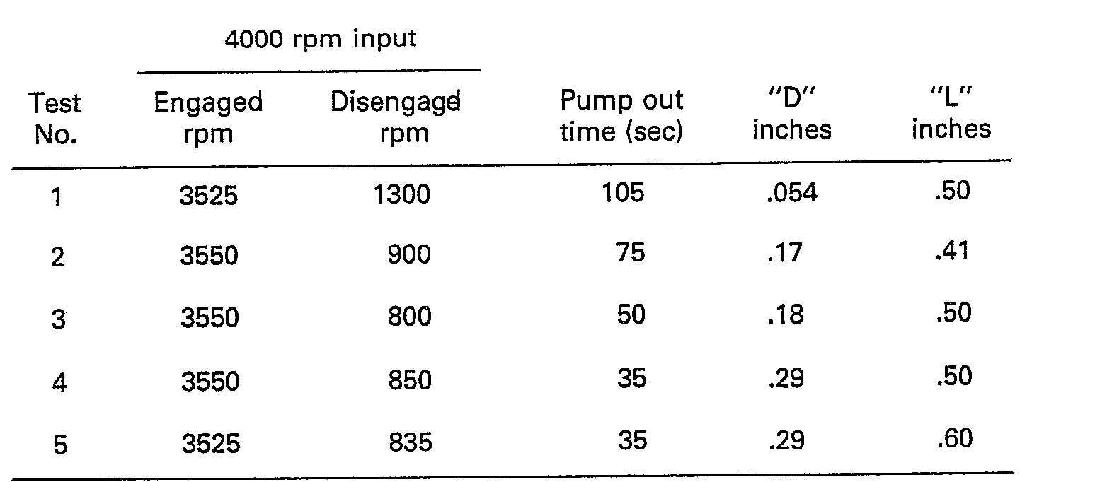
[0018] In each test, the viscosity and volume of the viscous fluid was held constant along
with the remaining measurements of the drive. The distance L from the rear edge 94
of the pumping element to the front edge 96 of the axially extending portion 76 was
varied as indicated in the table and shaped as illustrated in the drawings while the
length of from the rear edge 94 to the front edge 96a of radially extending portion
78 was held relatively constant at 0.5 inches (1.27 cm). As illustrated, the front
edge 96a defines opening 70 in Figs. 2, 6, 8, and 10.
[0019] Figs. 2-4 are representative of the pumping elements of tests 3 and 4. Figs. 6 and
7 are representative of the pumping element of test 2. Figs. 8 and 9 are representative
of the pumping element of test 5. Figs. 10 and 11 are representative of the pumping
element of test 1.
[0020] It is believed that the minimum length "L" of axially extending portion 76 should
be at least twenty percent of the maximum length of the radially extending portion
measured from rear edge 94 to front edge 96a in order to achieve the desired results.
By reducing "L" below twenty percent of the length of the radially extending portion,
it appears that the improvement will be marginal. The front edge 96 of axially extending
portion 76 should be located in line with or preferably forward of the rear edge of
opening 70. It should be noted that, although not tested, it is believed that pumping
element 64 may be constructed without an opening 70 as illustrated in Fig. 2a and
still accomplish the desired results. With the Fig. 2a pumping element, the front
edge 96a of the radially extending portion 78 is straight and aligned with the rear
edge 72a of outlet opening 72. It is also believed that the width "D" of axially extending
portion 76 should be at least fifty percent of the axial distance between surfaces
80 and 82 to achieve the desired results. Although widths "D" less than fifty percent
will show some improvement over pumping elements not having an axially extending portion
to reduce disengaged speeds, the pump out time will not be substantially reduced.
[0021] It is desirable to have the axially extending portion of the pumping out element
extend radially and axially as far as possible between the peripheral surfaces of
the clutch and housing members and the side surfaces of the housing member.
[0022] Since the pumping element, however, is secured to the housing member and the clutch
and housing members rotate relative to one another, adequate clearance should be provided
within acceptable manufacturing tolerances to ensure that the pumping element does
not rub against the clutch member.
[0023] If desired, the axially and radially extending portions may be separate and respectively
secured to casting 24 and valve plate 26. In such an assembly, the two portions would
be circumferentially aligned to ensure impingement and direction of the fluid into
opening 72. Further, it is desirable to locate the rear edge 72a of outlet opening
72 adjacent front edge 96a of radially extending portion 78 to achieve ultimate results.
[0024] It has also been determined that by making use of the improved pumping element that
lighter fans can be used on fan drives without increasing the disengaged speed. This
is achieved due to the more efficient pumping action of the improved pumping element.
1. A viscous fluid drive including a housing member (18) having axially spaced generally
radially extending side surfaces (80, 82) which, together with a generally axially
extending inner peripheral cylindrical surface (54) on said housing member, define
a working chamber (22), a reservoir (28) defined by said housing member adjacent said
working chamber, a clutch member (16) located within said working chamber and having
a pair of axially spaced generally radially extending side surfaces (44, 46) axially
spaced from said radially extending side surfaces of said housing member and a generally
axially extending outer peripheral cylindrical surface (52) spaced from said inner
peripheral surface of said housing member, viscous fluid within said working chamber
and said reservoir, an input shaft (12) rotatably secured to one of said members and
rotatably supporting said other member, an outlet opening (72) located in a radially
extending portion of said housing member adjacent said peripheral surfaces for communicating
fluid from said working chamber to said reservoir, the outlet opening having a front
edge (72b) at its upstream side, in relation to the circumferential direction of fluid
movement during operation of said drive, and a rear edge (72a) at its downstream side,
an inlet opening (40) in said housing member for communicating fluid from said reservoir
to said working chamber, condition responsive valve means (34, 36) to direct fluid
between said reservoir and said working chamber through one of said openings, and
a fixed pumping device (64) in said housing member for directing fluid out of the
working chamber through said outlet opening, said fixed pumping device (64) having
a radially extending portion (78) which is adjacent said outlet opening, projects
axially toward said adjacent clutch side surface (44), and has a front edge (96a)
which is substantially aligned with the rear edge of said outlet opening; characterised
in that the condition responsive valve means (34, 36) is associated with said inlet
opening and said fixed pumping device further includes an axially extending portion
(76) circumferentially aligned with said radially extending portion, projecting radially
a distance between said inner and outer cylindrical peripheral surfaces so as to form
a constriction in the space between them, and extending axially a distance between
said side surfaces of said housing member to impinge fluid flowing in the peripheral
direction between said cylindrical peripheral surfaces and thereby direct said impinged
fluid radially inwardly along said adjacent side surface of said members into contact
at one side with said front edge of said radially extending portion and into said
outlet opening.
2. A viscous fluid drive according to claim 1, characterised in that said radially
extending portion and said axially extending portion are secured together.
3. A viscous fluid drive according to claim 1 or claim 2, characterised in that said
front edge of said radially extending portion is configured in part to define an opening
(70) which bounds said outlet opening on three sides and is opened on the fourth side
to direct fluid into said opening of said pump and thereafter into said outlet opening.
4. A viscous fluid drive according to claim 3, characterised in that said front edge
of said axially extending portion is located to the rear of the most forwardly portion
of the front edge of said radially extending portion and forward of the rear edge
of said pump opening.
5. A viscous fluid drive according to claim 1, 2 or 3, characterised in that said
axially extending portion extends substantially between said side surface of said
housing member.
6. A viscous fluid drive according to claim 1, 2 or 3, characterised in that said
axially extending portion extends at least one-half of the distance between said side
surfaces of said housing member.
7. A viscous fluid drive according to claim 6, characterised in that the minimum length
of said axially extending portion is greater than twenty percent of the maximum length
of said radially extending portion.
8. A viscous fluid drive according to claim 6, characterised in that the front edge
(96) of said axially extending portion and the front edge of said radially extending
portion lie substantially in line with one another.
9. A viscous fluid drive according to claim 6, characterised in that the front edge
(96) of the axially extending portion is skewed relative to the axis of rotation of
said input shaft.
10. A viscous fluid drive having a rotatable clutch member (16) located in a working
chamber (22) within a rotatable housing member (18), an aperture (72) through which
working fluid can leave the working chamber, the aperture being in a radially extending
wall (26) of the housing member and facing a radially extending surface (74) of the
clutch member, and a fixed means (64) in said housing member for directing fluid out
through the aperture during relative rotation of the members, said fixed means (64)
comprising a portion (78) in register with the aperture in the radial direction, and
partly obstructing the space between said radially extending wall and radially extending
surface characterised in that said fixed means (64) has a portion (76) which is in
generally the same peripheral position as the portion (78) and which at least partly
obstructs and forms a constriction in the space between the peripheral inner cylindrical
surface (54) of the housing member and the peripheral outer cylindrical surface (52)
of the clutch member at a position in the peripheral direction, adjacent to said aperture.
1. Viskositätsfluidantrieb mit einem Gehäusteil (18), das axial in Abstand voneinander
liegende, im wesentlichen radial verlaufende Seitenflächen (80, 82) aufweist, die
zusammen mit einer im wesentlichen axial verlaufenden inneren zylindrischen Umfangsfläche
(54) des Gehäuseteils eine Arbeitskammer (22) bilden, einem von dem Gehäuseteil benachbart
der Arbeitskammer gebildeten Speicherraum (28), einem innerhalb der Arbeitskammer
angeordneten Kupplungsteil (16), das zwei axial in Abstand voneinander liegende, im
wesentlichen radial verlaufende, axial in Abstand von den radial verlaufenden Seitenflächen
des Gehäuseteils befindliche Seitenflächen (44, 46) und eine im wesentlichen axial
verlaufende äußere zylindrische Umfangsfläche (52) aufweist, die in Abstand von der
inneren Umfangsfläche des Gehäuseteils liegt, einem viskosen Fluid in der Arbeitskammer
und dem Speicherraum, einer mit einem der Teile drehfest verbundenen Antriebswelle
(12), welche das andere Teile drehbar abstützt, einer Auslaßöffnung (72), die sich
in einem radial verlaufenden Abschnitt des Gehäuseteils benachbart den Umfangsflächen
befindet, um Fluid von der Arbeitskammer zu dem Speicherraum gelangen zu lassen und
die an ihrer bezüglich der Umfangsrichtung der Fluidbewegung während des Arbeitens
des Antriebes stromaufwärts liegenden Seite eine Vorderkante (72b) sowie an ihrer
stromab liegenden Seite eine Hinterkante (72a) aufweist, einer Einlaßöffnung (40)
in dem Gehäuseteil, die Fluid von dem Speicherraum zu der Arbeitskammer gelangen läßt,
einer auf einen Zustand ansprechenden Ventilanordnung (34, 36), um Fluid zwischen
dem Speicherraum und der Arbeitskammer durch eine der Öffnungen hindurchzuleiten,
und einer festen Pumpeinrichtung (64) in dem Gehäuseteil, um Fluid durch die Auslaßöffnung
hindurch aus der Arbeitskammer herauszuleiten, wobei die feste Pumpeinrichtung (64)
einen radial verlaufenden Abschnitt (78) aufweist, der benachbart der Auslaßöffnung
liegt, axial in Richtung auf die benachbarte Kupplungsseitenfläche (44) vorragt und
eine Vorderkante (96a) aufweist, die mit der Hinterkante der Auslaßöffnung im wesentlichen
ausgerichtet ist, dadurch gekennzeichnet, daß die auf einen Zustand ansprechende Ventilanordnung
(34, 36) der Einlaßöffnung zugeordnet ist und die feste Pumpeinrichtung ferner einen
axial veraufenden Abschnitt (76) aufweist, der mit dem radial verlaufenden Abschnitt
umfangsmäßig ausgerichtet ist, zwischen den zylindrischen inneren und äußeren Umfangsflächen
radial um ein solches Stück vorsteht, daß in dem Raum zwischen diesen eine Verengung
gebildet wird, und der in Axialrichtung zwischen den Seitenflächen des Gehauseteils
eine Strecke weit verläuft, um in der Umfangsrichtung zwischen den zylindrischen Umfangsflächen
strömendes Fluid auftreffen zu lassen und dadurch das auftreffende Fluid radial einwärts
entlang der benachbarten Seitenfläche der Teile in Kontakt an einer Seite mit der
Vorderkante des radial verlaufenden Abschnitts und in die Auslaßöffnung zu lenken.
2. Viskositätsfluidantrieb nach Anspruch 1, dadurch gekennzeichnet, daß der radial
verlaufende Abschbitt und der axial verlaufende Abschnitt untereinander fest verbunden
sind.
3. Viskositätsfluidantrieb nach Anspruch 1 oder Anspruch 2, dadurch gekennzeichnet,
daß die Vorderkante des radial verlaufenden Abschnitts derart ausgestaltet ist, daß
sie zum Teil eine Öffnung (70) bildet, welche die Auslaßöffnung and drei Seiten begrenzt
und die an der vierten Seite offen ist, um Fluid in die Öffnung der Pumpe und danach
in die Auslaßöffnung zu lenken.
4. Viskositätsfluidantrieb nach Anspruch 3, dadurch gekennzeichnet, daß die Vorderkante
des axial verlaufenden Abschnitts hinter dem vordersten Abschnitt der Vorderkante
des radial verlaufenden Abschnitts und vor der Hinterkante der Pumpenöffnung angeordnet
ist.
5. Viskositätsfluidantrieb nach Anspruch 1, 2 oder 3, dadurch gekennzeichnet, daß
der axial verlaufende Abschnitt sich im wesentlichen zwischen den Seitenflächen des
Gehäuseteils erstreckt.
6. Viskositätsfluidantrieb nach Anspruch 1, 2 oder 3, dadurch gekennzeichnet, daß
sich der axial verlaufende Abschnitt über mindestens die Hälfte des Abstandes zwischen
den Seitenflächen des Gehäuseteils erstreckt.
7. Viskositätsfluidantrieb nach Anspruch 6, dadurch gekennzeichnet, daß die Mindestlänge
des axial verlaufenden Abschnitts größer als zwanzig Prozent der Höchstlänge des radial
verlaufenden Abschnitts ist.
8. Viskositätsfluidantrieb nach Anspruch 6, dadurch gekennzeichnet, daß die Vorderkante
(96) des axial verlaufenden Abschnitts und die Vorderkante des radial verlaufenden
Abschnitts im wesentlichen in einer Linie miteinander liegen.
9. Viskositätsfluidantrieb nach Anspruch 6, dadurch gekennzeichnet, daß die Vorderkante
(96) des axial verlaufenden Abschnitts mit Bezug auf die Drehachse de Antriebswelle
schräg steht.
10. Viskositätsfluidantrieb mit einem drehbaren Kupplungsteil (16), das in einer Arbeitskammer
(22) innerhalb eines drehbaren Gehäuseteils (18) sitzt, einer Öffnung (72), durch
die hindurch Arbeitsmittel die Arbeitskammer verlassen kann und die in einer radial
verlaufenden Wand (26) des Gehäuseteils vorgesehen sowie einer radial verlaufenden
Oberfläche (74) des Kupplungsteils zugewendet ist, und einer festen Einrichtung (64)
in dem Gehäuseteil, die während einer relativen Drehung der Teile Fluid nach außen
durch die Öffnung hindurchlenkt die einen Abschnitt (78) aufweist, der mit der Öffnung
in radialer Richtung fluchtet und den Raum zwischen der radial verlaufenden Wand und
der radial verlaufenden Oberfläche teilweise versperrt, dadurch gekennzeichet, daß
die feste Einrichtung (64) einen Abschnitt (76) aufweist, der im wesentlichen in der
gleichen Umfangsstellung wie der Abschnitt (78) liegt und der den Raum zwischen der
inneren zylindrischen Umfangsfläche . (54) des Gehäuseteils und der äußeren zylindrischen
Umfangsfläche (52) des Kupplungsteils an einer in der Umfangsrichtung der Öffnung
benachbarten Stelle mindestens teilweise versperrt und eine Verengung in diesem Raum
bildet.
1. Dispositif d'entraînement à fluide visqueux comprenant un organe formant carter
(18) présentant des surfaces latérales (80, 82) s'étendant sensiblement radialement
et axialement espacées et qui, conjointement avec une surface cylindrique périphérique
intérieure (54) s'étendant sensiblement axialement sur ledit organe formant carter,
définissent une chambre de travail (22), un réservoir (28) défini par ledit organe
formant carter en position adjacente à ladite chambre de travail, un organe d'embrayage
(16) disposé à l'intérieur de ladite chambre de travail et comportant deux surfaces
latérales (44, 46) s'étendant sensiblement radialement et espacées axialement entre
elles, ainsi qu'axialement espacées desdites surfaces latérales s'étendant radialement
ménagées sur ledit organe formant carter, et une surface cylindrique périphérique
extérieure (52) s'étendant sensiblement axialement, et espacée de ladite surface périphérique
intérieure ménagée sur ledit organe formant carter, un fluide visqueux à l'intérieur
de ladite chambre de travail et dudit réservoir, un arbre d'entrée (12) solidaire
en rotation de l'un desdits organes et supportant libre de rotation l'autre organe,
un orifice de sortie (72) ménagé dans une partie s'étendant radialement dudit organe
formant carter, à proximité desdites surfaces périphériques, et agencé pour permettre
la communication du fluide à partir de ladite chambre de travail vers ledit réservoir,
l'orifice de sortie présentant une arête frontale (72b), sur son côté amont, défini
par rapport à la direction circonférentielle du déplacement de fluide lors du fonctionnement
dudit dispositif d'entraînement, et une arête arrière (72a) sur son côté aval, un
orifice d'entrée (40) ménagé dans ledit organe formant carter et destiné à permettre
au fluide de passer, à partir dudit réservoir, vers ladite chambre de travail, des
moyens formant soupape (34, 36) sensibles à des paramètres de fonctionnement et agencés
pour diriger le fluide entre ledit réservoir et ladite chambre de travail à travers
l'un desdits orifices et un appareil de pompage fixe (64) à l'intérieur dudit organe
formant carter pour diriger du fluide à partir de la chambre de travail à travers
l'orifice de sortie, l'appareil de pompage fixe (64) possédant une partie s'étendant
radialement (78) qui est adjacente audit orifice de sortie, qui fait saillie axialement
vers ladite surface latérale adjacente (44) de l'organe d'embrayage, et présente une
arête frontale (96a) qui est sensiblement alignée avec l'arête arrière dudit orifice
de sortie, caractérisé en ce que les moyens formant soupape (34, 36) sensibles à des
paramètres de fonctionnement, sont associés à l'orifice d'entrée et que l'appareil
de pompage comprend en outre une partie s'étendant axialement (76) circonférentiel-
lement alignée avec ladite partie s'étendant radialement, qui s'étend radialement
d'une certaine distance entre lesdites surfaces périphériques cylindriques intérieure
et extérieure pour former un resserrement dans l'espace qui les sépare et s'étend
axialement d'une certaine distance entre lesdites surfaces latérales dudit organe
formant carter, de façon à heurter le fluide circulant dans la direction périphérique
entre lesdits surfaces périphériques cylindriques pour diriger ledit fluide heurté,
radialement vers l'intérieur le long desdites surfaces latérales adjacentes desdits
organes, pour le mettre en contact d'un côté avec ladite arête frontale de ladite
partie s'étendant radialement, et pour qu'il pénètre dans ledit orifice de sortie.
2. Dispositif d'entraînement à fluide visqueux selon la revendication 1, caractérisé
par le fait que ladite partie s'étendant radialement et ladite partie s'étendant axialement
sont fixées ensemble.
3. Dispositif d'entraînement à fluide visqueux selon l'une des revendications 1 et
2, caractérisé par le fait que ladite arête frontale de ladite partie s'étendant radialement
est conformée en partie pour définir une ouverture (70) qui entoure ledit orifice
de sortie surtrois côtés et est ouverte sur le quatrième côté pour diriger le fluide
dans ladite ouverture de ladite pompe, puis dans ledit orifice de sortie.
4. Dispositif d'entraînement à fluide visqueux selon la revendication 3, caractérisé
par le fait que l'arête frontale de ladite partie s'étendant axialement est située
à l'arrière de la partie la plus avancée de l'arête frontale de ladite partie s'étendant
radialement et à l'avant de l'arête arrière de ladite ouverture de la pompe.
5. Dispositif d'entraînement à fluide visqueux selon l'une des revendications 1 à
3, caractérisé par le fait que ladite partie s'étendant axialement s'étend sensiblement
entre lesdites surfaces latérales dudit organe formant carter.
6. Dispositif d'entraînement à fluide visqueux selon l'une des revendications 1 à
3, caractérisé par le fait que ladite partie s'étendant axialement s'étend au moins
sur la moitié de la distance entre lesdites surfaces latérales dudit organe formant
carter.
7. Dispositif d'entraînement à fluide visqueux selon la revendication 6, caractérisé
par le fait que la longueur minimale de ladite partie s'étendant axialement est supérieure
à vingt pour cent de la longueur maximale de ladite partie s'étendant radialement.
8. Dispositif d'entraînement à fluide visqueux selon la revendication 6, caractérisé
par le fait que l'arête frontale (96) de ladite partie s'étendant axialement et l'arête
frontale de ladite partie s'étendant radialement sont sensiblement alignées l'une
avec l'autre.
9. Dispositif d'entraînement à fluide visqueux selon la revendication 6, caractérisé
par le fait que l'arête frontale (96) de ladite partie s'étendant axialement est orientée
en biais par rapport à l'axe de rotation dudit arbre d'entrée.
10. Dispositif d'entraînement à fluide visqueux comprenant un organe d'embrayage rotatif
(16) disposé dans une chambre de travail (22) prévue à l'intérieur d'un organe formant
carter rotatif (18), une ouverture (72) à travers laquelle un fluide d'entraînement
peut être évacué de la chambre de travail, l'ouverture étant ménagée dans un paroi
s'étendant radialement (26) de l'organe formant carter et faisant face à une surface
s'étendant radialement L74) de l'organe d'embrayage, et des moyens fixes (64) dans
ledit organe formant carter, agencée pour diriger le fluide vers l'extérieur à travers
l'ouverture lors de la rotation relative des organes, lesdits moyens fixes (64) comprenant
une partie (78) qui coïincide avec l'ouverture dans la direction radiale, et obture
partiellement l'espace compris entre la paroi s'étendant radialement et la surface
s'étendant radialement, caractérisé en ce que les moyens fixes (64) possèdent une
partie (76) qui est sensiblement dans la même position périphérique que la partie
(78) et qui obture au moins partiellement l'espace situé entre la surface (54) cylindrique
périphérique intérieure de l'organe formant carter et la surface cylindrique (52)
périphérique extérieure de l'organe d'embrayage et forme une restriction dans cet
espace, dans une position, dans la direction périphérique, adjacente à ladite ouverture.