| (19) |
 |
|
(11) |
EP 0 138 940 B1 |
| (12) |
EUROPEAN PATENT SPECIFICATION |
| (45) |
Mention of the grant of the patent: |
|
18.03.1987 Bulletin 1987/12 |
| (22) |
Date of filing: 05.04.1984 |
|
| (86) |
International application number: |
|
PCT/NO8400/019 |
| (87) |
International publication number: |
|
WO 8403/942 (11.10.1984 Gazette 1984/24) |
|
| (54) |
METHOD AND APPARATUS FOR MEASURING THE DISTANCE TO AN OBJECT
VERFAHREN UND VORRICHTUNG ZUM MESSEN DES ABSTANDES BIS ZU EINEM GEGENSTAND
PROCEDE ET APPAREIL DE MESURE DE LA DISTANCE D'UN OBJET
|
| (84) |
Designated Contracting States: |
|
AT BE CH DE FR GB LI LU NL SE |
| (30) |
Priority: |
05.04.1983 NO 831198
|
| (43) |
Date of publication of application: |
|
02.05.1985 Bulletin 1985/18 |
| (71) |
Applicant: AUTRONICA A/S |
|
N-7000 Trondheim (NO) |
|
| (72) |
Inventors: |
|
- BEKKADAL, Fritz
N-7075 Tiller (NO)
- SCHAUG-PETTERSEN, Tor
N-7000 Trondheim (NO)
|
| (74) |
Representative: Betten, Jürgen, Dipl.-Ing. |
|
Betten & Resch Patentanwälte
Reichenbachstrasse 19
80469 München
80469 München (DE) |
|
| |
|
| Note: Within nine months from the publication of the mention of the grant of the European
patent, any person may give notice to the European Patent Office of opposition to
the European patent
granted. Notice of opposition shall be filed in a written reasoned statement. It shall
not be deemed to
have been filed until the opposition fee has been paid. (Art. 99(1) European Patent
Convention).
|
[0001] The invention relates to a method, as stated in the introductory part of claim 1,
to determine the distance to an object, particularly to the surface of a liquid or
another flowable medium in a container or similar enclosure.
[0002] Further the invention relates to a device for such a determination of distance, as
stated in the introductory part of claim 10. Methods and devices as stated in the
introductory part of these claims are previously known, see e.g. FR-A-2141844, FR-A-2385085,
GB-A-1234791, GB-A-2083312, US-A-4044355, US―A―4218678.
[0003] The terminology used in this specification relating to microwave technology is in
accordance with the definitions in IEC Standard, Publication 615: "Terminology for
microwave apparatus", Geneve, Switzerland, 1976.
[0004] For the purpose stated above the following methods based on radiation of electromagnetic
waves are known and used:
Pulse radar
[0005] The signal is transmitted as short pulses. The received signal consists of a series
of pulses corresponding to echoes from different distances. The signal processing
consists of time and amplitude determination of the echo pulses, which requires very
fast acting circuits. The resolution will increase with decreasing pulse length
T. A new pulse cannot be transmitted before all significant echoes have returned. If
the interval between transmission of pulses is T, the ratio of peak power to average
power for the radar transmitter will be TIT. To avoid distortion of the pulses, the
radar receiver should have a bandwidth > 1/
T.
Chirp radar
[0006] This type of radar differs from the pulse radar in the method of generation and detection
of pulses only. The transmitted signal has a longer duration, but is frequency modulated,
the frequency changing from the lowest to the highest value, or vice versa, of the
pulse spectrum. In the receiver the signal is passed to a matched filter which delays
the low frequencies relatively to the high ones and compresses the signal to a pulse
of the same length as in a pulse radar with the same resolution. After compression,
the signal processing is the same for the two systems. The chirp radar requires lower
peak power than the pulse radar, but needs a matched filter.
FM-radar
[0007] In this type of radar the transmitted signal has a constant amplitude. It is frequency
modulated linearly and periodically from the lowest to the highest frequency in the
band, or vice versa, similarly to the chirp radar, but the frequency scan can be of
longer duration. A part of the transmitted signal is branched off and used as a local
oscillator signal for a receiving mixer in which it is mixed with the reflected signal.
Due to the time delay of the reflected signal, a beat frequency proportional to the
distance to the reflecting object is created. Different contributions to the reflected
signal appear as different frequency components in the received signal.
[0008] Analysis of the received signal is carried out in a filter bank or by means of one
or more tunable filters. The receiver may be narrow-banded, but the scanning time
must be short for the beat frequency to be in the low noise region of the receiver.
Reflectometer
[0009] By this method the reflection coefficient p = r·e
jΨof the antenna is measured over a frequency range corresponding to the spectrum of
the radar pulse. Here r is the module (amplitude) of the reflection coefficient and
(p its phase, e is the base of the natural logarithm and j = V - 1. The reflection
coefficient p(f), where f is the frequency, is measured for a series of discrete frequencies
evenly distributed over the frequency range. The measured values are fed to a microprocessor
or computer performing a Fourier transformation of p(f) from the frequency domain
to the time domain. The result is a time function corresponding to the reflected signal
of a pulse radar system. Systems based on this method may thus be termed synthesized
pulse radar systems. The pulse will not, however, be present in real time, but contained
in a data set, which implies great advantages for the signal analysis.
[0010] The present invention utilizes the reflectometer principle described above combined
with a number of special methods of signal generation and processing which will give
the measurements more accuracy and flexibility than existing methods and give other
advantages to be described below.
[0011] Systems based on the reflectometer method cannot operate in real time, as indicated
above. It is then convenient to use digital signal processing, which will give the
system some characteristic features. A discrete Fourier transformation (DFT) has to
be carried out, preferably with equidistant frequencies when using fast DFT-algoritms,
such as "Fast FourierTransform" (FFT). If the distance between the frequencies in
this equidistant set is Af, the time representation of the reflection coefficient
p(f) obtained by a discrete Fourier transformation will be periodic with a period
T = 1/Af. Two contributions to p(f) with time delays
T1 and
T2 will appear at the same location in the time representation if
T2 -
T1 = nT, where n is an integer (n = 0,1, 2,...). It is thus necessary first to choose
T larger than the largest value,
Tmax. of then time delay
T within the measurement range. Further T should be chosen so large that no significant
interfering reflections have time delays larger than T.
[0012] A simplification of the system can be achieved by measuring only the real part, Re{p(f)},
or only the imaginary part im{p(f)}, of the complex reflection coefficient p(f). If
the phase of the reference signal, the signal to which the reflected signal from the
antenna is compared, is set to 0, a reflected signal with time delay
T will give a contribution to p(f) which is proportional to e-
j2fr. The real part of this contribution is Re{e
-j2Πfr} = cos (2nfr) = 1/2[e
j2Πfr+ e-
J2Πfr], which will give contributions of equal strengths at time delays
T and -
T. Due to the said periodicity of the discrete Fourier transformation, the contribution
with time delay -
T also appears with the time delay T-
T. This means that, when only the real part or the imaginary part of p(f) is measured,
T has to be chosen so large that the maximum time delay within the range of measurement,
Tmax, is less than T/2.
[0013] A difficulty in measuring the distance to an object by using a freely radiating antenna
is caused by the substantial decrease in the reflected signal with increased distance
to the object. For a plane reflecting surface, as an important special case, the amplitude
of the reflected signal is inversely proportional to the distance from the antenna,
provided that the distance exceeds a certain threshold; while the reflected amplitude
for an object of small angular extension is inversely proportional to the distance
squared. Such is the case when the medium between the antenna and the object is loss
free. If electromagnetic waves are significantly attenuated in the said medium, the
amplitude of the received signal will decrease more strongly with distance than stated
above.
[0014] Problems related to digital signal processing arise particularly when the desired
signal is only a small fraction of the total signal. A large resolution is then needed,
i.e. a large number of digits in the digital representation of the signal. A considerable
improvement in this respect is achieved by the present invention which, instead of
using the values of the reflection coefficient of the antenna itself in the Fourier
transformation, utilizes a function of the reflection coefficient which is adapted
to the system configuration and to the type of object to be measured, and then performs
a Fourier transformation of this function.
[0015] When measuring towards a plane surface through a medium with low attenuation, the
optimum choice of function is the derivative of the reflection coefficient p(f), with
respect to frequency, i.e.
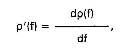
as the following calculation will show:
[0016] If F {x} is the Fourier transform of x and

then
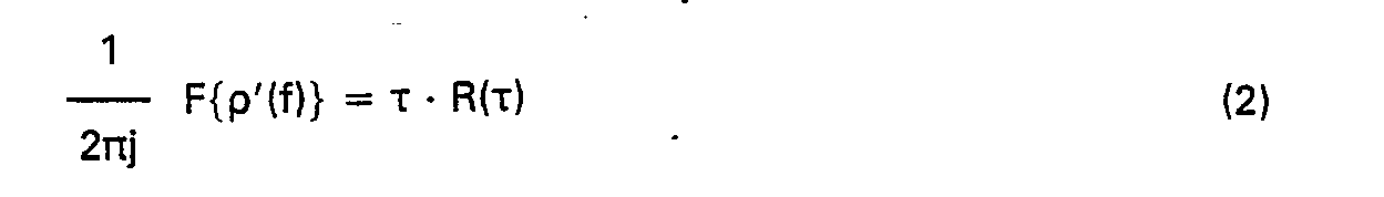
[0017] This shows that by using the derivative of p(f), the contribution from larger distances
will be emphasized relatively to the contribution from smaller distances and be in
proportion to this distance. The echo amplitude from a large, plane surface will then
be independent of the distance from the antenna.
[0018] In a practical case, not p'(f), but the differential of p(f), Ap(f) will be measured,
by subtracting the values of p(f) at 2 frequencies differing by f
d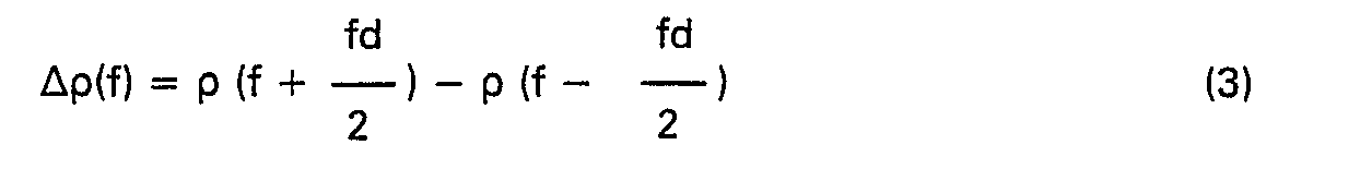
This process should be carried out before the analog to digital signal conversion
in order to obtain the abovementioned reduction in the necessary digital resolution.
[0019] To obtain the differential of p(f) or its real or imaginary part, the following method
is convenient: The microwave signal input to the antenna changes between two frequencies
whose difference is
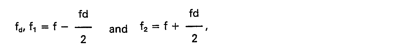
where f is the nominal measurement frequency. The signal reflected from the antenna
terminal is fed to a detection circuit whose output voltage V is proportional to,
e.g., Re{p}. When the frequency varies between f
1 and f
2, V will vary between V
t~ Re{p(f
1)} and V2~ Re{p(f
2)}. The voltage ΔV = V
2 - V
1 is then a measure of Re{p(f
2)} - Re{p(f
1)}. Similarly a higher differential can be formed by changing the frequency between
n values f
1, f
2, ..., f
n, and selecting a suitable linear combination of the corresponding detected voltages
V
1, V
2, ..., V
n.
[0020] To achieve a high accuracy in the measurement according to the present invention,
it is necessary to know the frequencies at which the values of the function of the
antenna input reflection coefficient are measured, the measurement frequencies, with
high accuracy. This can in principle be obtained by synthesizing the measurement frequencies
or by using e.g. a frequency counter of sufficient accuracy. These methods will, however,
be both expensive and time consuming, and the following method is chosen in the present
invention:
The microwave signal is generated by a voltage controlled oscillator (VCO), and the
control voltage varies to increase or decrease the frequency substantially linearly
with time. The measurements may then suitably be taken at constant intervals of time.
The signal is split in two equal parts, one part being used for measuring the reflection
from an impedance element, the reference impedance, whose reflection coefficient is
a known function of frequency. The frequency impedance is measured at the same or
at some of the same frequencies as the antenna.
[0021] If the reflection coefficient p, of the reference impedance at the frequency of measurement
f
k is ρ
rk, f
k is determined by solving the equation:

wherein p
r(f) expresses the known frequency dependence of ρ
r. The frequency f would then in principle have to be a single-valued function of ρ
r over the total frequency range. If it is known, however, that f
k lies between two frequencies f
a and f
b, the distance between which being less than the total frequency range, it is sufficient
that f is a single-valued function of p, in the frequency range f
a to f
b.
[0022] This method will normally not ensure equidistant measurement frequencies, and suitable
interpolation routines are used when an equidistant set of frequencies is needed,
as for an FFT-algorithm.
[0023] In the preceding, it is assumed that the object being measured is stationary. If
the object is moving, as, e.g., the surface of a liquid in a container being filled
or emptied, errors of measurement may occur.
[0024] Assume that the measurement is carried out in the frequency range (f
o - AF/2, f
o + ΔF/2), i.e. in a frequency range of width ΔF around the center frequency f
o, and that the duration of the measurement is To. If the distance to be measured changes
from h
1 to h
2 during the time To, the phase of the reflection coefficient changes from ϕ
1 = 4π(f
o - ΔF/2)h
1/c to ϕ
2= 4π(f
o + ΔF/2)h
2/c where c is the velocity of light in the medium between the antenna and the object,
provided that the measurement is made with increasing frequency.
[0025] The phase change will then be:
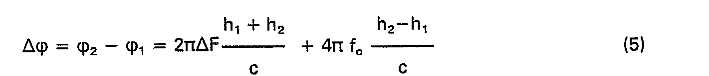
[0026] This should be compared to the phase change for an object at rest at a distance h,
which will be 4πΔFh/c by making h
1 = h
2 = h in (5). The apparent distance to the moving object will then be:

In this equation the average distance

is the natural definition of the distance to a moving object, the expression (f
o/ΔF) (h
2 - h
i) represents the error.
[0027] If e.g. f
o/ΔF is equal to 10, e.g. an error of measurement results which is 10 times the change
of distance during the time of measurement. This error can be eliminated by making
another measurement with the frequency decreasing from f
o + AF/2 to f
o - ΔF/2 during the time of measurement T
o. If the object is moving at an even rate, the last measurement will give an error
with the same absolute value at the first, but of opposite sign. By averaging the
two measurements, a distance is determined, which corresponds to the distance in the
middle of the total period of measurement.
[0028] The objects of the invention are achieved by carrying out the method according to
claim 1. Further features of the invention, including a device for carrying out the
method, are described in the dependent claims.
[0029] The invention will be described in more detail with reference to the accompanying
drawings, which show possible realizations of the invention:
Fig. 1 shows schematically the layout of a device according to the invention for measuring
the level in a container, comprising an antenna 11, a measuring unit 12, a channel
unit 13 and a monitoring unit or central unit 14, which will all be further described
below. In the case that the object to be measured is the level 17 of the liquid 16
in a container 15, the antenna is placed at the top of the container as shown.
Figs. 2 to 4 show block diagrams of some realizations of the measuring unit 12 of
Fig. 1.
[0030] The measuring unit according to Fig. 2 functions as follows: In the measuring unit
12 a microwave signal is generated by a microwave generator 18, which may be a voltage
controlled oscillator, and is split in a power divider 19 between an antenna measurement
unit 20 in channel A and a frequency calibration unit 21 in channel B. The control
voltage for the microwave generator 18 is provided by a frequency control unit 22,
which makes the signal frequency assume a set of nominal values. To produce the set
of frequencies around each measuring frequency, which is needed to create the described
function of the antenna reflection coefficient, an additional voltage from a function
control unit 23 is superimposed upon the control voltage. This voltage is also input
to the detection units 24A and 24B, to give the contribution from each frequency the
desired weight.
[0031] The circuit of Fig. 3 differs from that of Fig. 2 is the manner of production of
the set of frequencies around each measurement frequency. In a steered phase shifter
26 the phase of the microwave signal is increased by ψ during an interval T
1. The frequency of the microwave signal will then increase by

By varying ↓ and/or T
1 the frequency change can be controlled and the desired set of frequencies generated.
It is not necessary, however, to increase the phase linearly with the time in the
interval T
1, the phase may be increased in one or several steps, by means of a multiple phase
modulator.
[0032] The circuit of Fig. 4 differs from that of Fig. 3 by using two steered phase shifters
27A and 27B, one for the signals to the antenna, and one for the signals to the reference
impedance. It will then be possible to use different functions for the two channels,
A and B.
[0033] The antenna measuring unit 20 and the frequency calibration unit 21 may be embodied
as reflectometers. In Fig. 5 is shown a block diagram for an embodiment of a reflectometer.
The microwave signal from the power divider 19 is input to a second power divider
30. A part of the signal is used as a reference signal (local oscillator) in a mixer
32, while another part is input to a duplexing circuit 31. From the duplexing circuit
31 the signal is transmitted to the impedance to be measured, the reflected signal
being transferred from the duplexing unit 31 to the mixer 32, in which it is mixed
with the reference signal, producing a low frequency signal going to the detection
unit 24 (24A and 24B).
[0034] The detected signals in channel A (from the antenna measuring units 20), and in channel
B (from the frequency calibrating unit 21) are converted from analog to digital form
in unit 13 and stored in a data memory or register in a data aquisition unit 28, to
make the measured data from the two channels available for further processing in a
signal processing unit 29.
[0035] A schematic diagram showing the main functions of the signal processing unit 29 is
shown in Fig. 6. These will be further described below.
[0036] From the data aquisition unit 31 values of the described function of the reflection
coefficient of the antenna at a finite number discrete frequencies within a certain
range of frequencies are present in channel A and values of the described function
of the reflection coefficient for the reference impedance at the same or some of the
same measuring frequencies in channel B.
[0037] By the data from channel B, the measuring frequencies (f) are determined by a routine
33 for frequency calculation. These frequencies are used in an interpolation routine
34 to find values of the described function for channel A at a given set of frequencies
which is compatible with the subsequent signal processing, in the case that this set
of frequencies and the set of measurement frequencies are not identical. This set
of function values are then Fourier transformed, followed by a selection of the contribution
from the object and calculation of the distance by means of routines 36, adapted to
the signal, and utilizing previously established data for the measurement path.
[0038] The measurements and calculations are carried out as described for two sequencies
in rapid succession, one for increasing frequencies and the other for decreasing,
to eliminate errors due to uniform change in the distance to the object during the
interval of measurement, by a process of averaging included in the processing routines
36.
[0039] By the monitoring unit 14 the various other units and circuits are monitored and
controlled, parallel to the computation of other user data based on data from the
signal processing unit in the described channel unit 13, as well as from tables of
information stored, other calculating units, sensors etc.
[0040] The monitoring unit 14 may handle several of the described channel units by using
a multiplexing circuit between the channel units and the detector unit to select in
turn each of the channel units connected in parallel to the multiplexing circuit.
[0041] Correspondingly the channel unit 13 can be used for several-measuring units with
a multiplexing circuit between the measuring units and the channel unit, or the signal
processing unit 29 of the channel unit 13 can be used for several data aquisition
units, each connected to a measuring unit, by using a multiplexing circuit between
the data aquisition units and the signal processing unit.
1. Method for measuring the distance to the surface of an object, particularly for
determining the distance to the surface of a liquid or another flowable medium in
a container or similar environment, wherein a microwave signal with predetermined
frequency is generated, a part of which is used as a reference signal, while a second
part is fed to an antenna, which is directed against said surface at a distance therefrom,
whereby the surface and other objects present influence the input impedance of the
antenna and the corresponding input reflection coefficient through their distance
dependent contributions to the said reflection coefficient characterized by a function
of the input reflection coefficient being formed as a combination of values of the
reflection coefficient at at least two different frequencies in an interval around
the nominal frequency of measurement, the combination being chosen in such a manner
that contributions to the said function from objects at certain distances being emphasized
relative to contributions from objects at other distances, in that a Fourier transformation
is made starting with a set of values of this function at a chosen set of frequencies,
in that the different contributions of the objects to the function resulting from
the Fourier transformation being separated according to the different distances from
the antenna of the objects from which the said contributions originated, in that contributions
from fixed objects being eliminated, their contributions to the Fourier transformed
function being known, and thereby the contribution of the surface being selected on
account of its strength and/or position, to enable the determination of the distance
to the surface.
2. Method according to claim 1, characterized by the said function being chosen, when
measuring the distance to a plane surface, as the differential of the input reflection
coefficient of the antenna or of its real or imaginary part, the said differential
being defined as the derivative with respect to frequency of the reflection coefficient
and approximated by the difference between the values of the reflection coefficient
at two different frequencies within an interval around the nominal frequency of measurement.
3. Method according to claim 1, characterized by the said function being chosen, when
measuring the distance to an object of limited angular extension relative to the directions
from the antenna, as the second order differential of the complex input reflection
coefficient of the antenna, the said differential being defined as the second derivative
with respect to frequency of the reflection, and approximated by a corresponding linear
combination of the values of the reflection coefficient at three or more different
frequencies in interval around the nominal frequency of measurement.
4. Method according to one of the claims 1-3, characterized by the said function being
chosen, when measuring the distance to an object surrounded by a medium in which the
electromagnetic waves are substantially attenuated, as a combination, adapted to the
measuring situation, of differentials of different orders of the reflection coefficient,
the differentials being defined as with respect fo frequency deviations of corresponding
orders the respect to frequency of the reflection coefficient, being approximated
by a combination of values of the reflection coefficient at a corresponding number
of frequencies within an interval around the nominal frequency of measurement.
5. Method according to one of the claims 1-4, characterized by a set of values of
the said function being formed, the said set consisting of the values of the function
at a chosen set of discrete frequencies within a chosen range, and a discrete Fourier
transformation of the said set of values being performed, the set of frequencies being
chosen so as to achieve a certain accuracy and to ensure that the indication of distance
is unambiguous within the chosen range of measurement.
- 6. Method according to claim 1, wherein the values of the said measurement frequencies,
at which the values of the said function is measured, are not accurately known at
the time of measurement, characterized by the said set of measurement frequencies
being sufficiently dense to allow interpolation of the values of the said function
at intermediate frequencies, by the values of the said function being measured for
a suitable, frequency dependent impedance element, the reference impedance, for the
same, or part of the same set of measuring frequencies, by the values of the measuring
frequencies being accurately determined from the measurements of the reference impedance,
and by the values of the said function of the antenna input reflection coefficient
being calculated for another set of frequencies adapted to the subsequent signal processing.
7. Method according to claim 1, characterized by the sequence of measurements to obtain
values of the said function being carried out twice in close succession, once with
a sequence of increasing measuring frequencies and once with decreasing frequencies,
or vice versa, in order to eliminate errors due to a possible change of the distance
to the object during the time of measurement.
8. Method according to one of the claims 1-5, characterized by the values of the reflection
coefficient used in the said function being obtained by feeding a signal with a single
frequency component to the antenna, the frequency of this component taking on a sequence
of values in an interval around the nominal measuring frequency, and by detector circuits
being used to obtain the values of the said function, in which circuits the reflected
signal is mixed with a reference signal, the detector circuits being synchronized
with the time variation of the transmitted signal and being designed to produce a
weighted sum of the different values of the reflection coefficient, whereby the desired
value of the said function appears after detection.
9. Method according to one of the claims 1-5, characterized by the values of the reflection
coefficient used to obtain the value of the said function being found by letting the
signal fed to the antenna be composed of at least two frequency components whose frequencies
take on, in time sequence, a set of values in an interval around the nominal measuring
frequency, and by detector circuits being used to obtain the values of the said function,
in which circuits the reflected signal is mixed with a reference signal, the detector
circuits being synchronized with the time variation of the transmitted signal and
being designed to produce a weighted sum of the different values of the reflection
coefficient, whereby the desired value of the said function appears after detection.
10. Device for carrying out measurements according to claim 1, comprising an antenna
(11) placed at a distance from, and pointing towards a surface (17), whose distance
from the antenna is to be determined, a measuring unit (12) and signal processing
circuits (28, 29), characterized by comprising a controllable frequency microwave
generator (18), a frequency steering unit (23) and detection units (24A, 24B) to form
the said function of the antenna input reflection coefficient for a set of discrete
measuring frequencies within a certain frequency range, and by the signal processing
circuits comprising means to perform a Fourier transformation of the set of function
values, to process the data obtained and to calculate the distance to be determined.
11. Device according to claim 10, characterized in that it comprises one or more controlled
phase shift circuits (26, 27A, 27B) to form the described function.
12. Device according to claim 10 and 11, characterized in that the measuring unit
(12) comprises a signal divider (19) splitting up the signal from the microwave generator
(18) to an antenna measuring unit (20) and to a frequency calibrating unit (21) which
are both connected to detection units (24A, respectively 24B) which in turn are connected
to the data processing unit (28) for transforming the signals detected from the antenna
measuring unit (20) and from the frequency calibrating unit (21) into digital form
and to supply these signals to the signal handling unit (29).
13. Device according to one of the claims 10-12, characterized in that the circuitry
for forming the described function of the reflection coefficient comprises means (22,
23, 26, 27A, 27B) for changing the amplitude, frequency and/or phase of the microwave
signal and detector circuits (24A, 24B) synchronized with the signal supplied to the
antenna and/or to reference impedance.
14. Device according to one of the claims 12 or 13, characterized in that the antenna
measuring unit (20) and the frequency calibrating unit (21) each comprise a reflectometer,
the antenna measuring unit (20) containing a duplexing circuit (31) connected to the
antenna (11), while in the frequency calibrating unit (21) a duplexing circuit is
connected to a frequency dependent reference impedance element.
1. Verfahren zum Messen des Abstands zu der Oberfläche eines Objekts, insbesondere
zur Bestimmung des Abstands zur Oberfläche einer Flüssigkeit oder eines anderen fließfähigen
Mediums in einem Behälter oder einem ähnlich abgeschlossenen Raum, bei dem ein Mikrowellensignal
mit vorbestimmter Frequenz erzeugt wird, von dem ein Teil als Bezugssignal verwendet
und ein zweiter Teil der Antenne zugeführt wird, die gegen die Oberfläche gerichtet
und in einem Abstand dazu angeordnet ist, wobei die Oberfläche und andere vorhandene
Objekte die Eingangsimpedanz der Antenne und den entsprechenden Eingangsreflexionskoeffizienten
über ihre abstandsabhängigen Beiträge zum Reflexionskoeffizienten beeinflussen, dadurch
gekennzeichnet, daß eine Funktion des Eingangsreflexionskoeffizienten der Antenne
durch eine Kombination von Werten des Reflexionskoeffizienten bei mindestens zwei
Frequenzen in einem Intervall um eine Nennmeßfrequenz herum so gebildet wird, daß
die Beiträge zu dieser Funktion von den Objekten in bestimmten Abständen relativ zu
Beiträgen von Objekten in anderen Abständen betont bzw. bewertet werden, daß eine
Fouriertransformation bezüglich einer Reihe von Werten dieser Funktion beginnend mit
einer vorbestimmten Reihe von Meßfrequenzen durchgeführt wird, daß die Beiträge der
verschiedenen Objekte zur fouriertransformierten Funktion entsprechend ihren verschiedenen
Abständen zur Antenne aufgetrennt werden, daß feste Beiträge von anderen Objekten,
deren Beiträge zur Fouriertransformierten Funktion bekannt sind, eliminiert werden
und dadurch der Beitrag der Oberfläche aufgrund seiner Stärke und/oder Position herausdividiert
wird, um die Bestimmung des Abstands zur Oberfläche zu ermöglichen.
2. Verfahren nach Anspruch 1, dadurch gekennzeichnet, daß die beschriebene Funktion
beim Messen des Abstands zu einer ebenen Oberfläche als Differential des komplexen
Eingangsreflexionskoeffizienten der Antenne oder dessen realen oder imaginären Teils
gebildet wird, wobei das Differential als Ableitung nach der Frequenz des Reflexionskoeffizienten
definiert oder als Differenz zwischen den Werten des Reflexionskoeffizienten bei zwei
verschiedenen Frequenzen in einem Intervall um die Nennmeßfrequenz herum angenähert
wird.
3. Verfahren nach Anspruch 1, dadurch gekennzeichnet, daß die beschriebene Funktion
beim Messen des Abstands zu einem Objekt mit einem begrenzten Winkelmaß relativ zur
Ausrichtung der Antenne als Differential zweiter Ordnung des Eingangsrflexionskoeffizienten
der Antenne gebildet wird, wobei das Differential zweiter Ordnung als zweite Ableitung
nach der Frequenz des Reflexionskoeffizienten definiert und als eine entsprechende
Linearkombination der Werte des Reflexionskoeffizienten bei drei oder mehr aufeinanderfolgenden
Frequenzen in einem Interval um die Nennmeßfrequenzy herum angenähert wird.
4. Verfaharen nach einem der Ansprüche 1 bis 3, dadurch gekennzeichnet, daß die beschriebene
Funktion beim Messen des Abstands von Objekten, die von einem Medium umgeben sind,
in dem die elektromagnetischen Wellen stark gedämpft werden, als eine an die bestehende
Dämpfung angepaßte Kombination von Differentialen verschiedener Ordnung des Eingangsreflexionskoeffizienten
der Antenne gewählt wird, wobei das allgemeine Differential n-ter Ordnung als die
Ableitung n-ter Ordnung des Antenneneingangsreflexionskoeffizienten nach der Frequenz
definiert oder als entsprechende Kombination von Werten des Reflexionskoeffizienten
bei entsprechenden Frequenzen in einem Intervall um die Nennmeßfrequenz herum angenähert
wird.
5. Verfahren nach einem der Ansprüche 1 bis 4, dadurch gekennzeichnet, daß die Werte
der beschriebenen Funktion des Antenneneingangsreflexionskoeffizienten für eine endliche
Anzahl diskreter Meßfrequenzen innerhalb eines begrenzten Frequenzbereiches gebildet
werden und daß dann eine diskrete Fouriertransformation der Werte der Funktion durchgeführt
wird, wobei die Meßfrequenzen so gewählt werden, daß eine vorbestimmte Gernauigkeit
erreicht und das Meßergebnis im gewählten Meßbereich eindeutig ist.
6. Verfahren nach Anspruch 1, bei dem die Meßfrequenzen, bei denen die Werte der Funktion
des Eingangsreflexsionskoeffizienten der Antenne bestimmte werden, zum Zeitpunkt der
Messung nicht genau bekannt sind, dadurch gekennzeichnet, daß die Meßfrequenzen ausreichend
nahe beieinander gewählt werden, um eine Interpolation der Funktionswerte bei Zwischenfrequenzen
zu ermöglichen, daß Funktionswerte für ein geeignet ausgewähltes, frequenzabhängiges
Impedanzelement als Bezugsimpedanz bei den gleichen oder einem Teil der gleichen Meßfrequenzen
bestimmit werden, und daß die Meßfrequenzen aus Messungen an der Bezugsimpedanz genau
bestimmt werden und daß die Funktionswerte des Eingagnsreflexionskoeffizienten der
Antenne bei einer anderen Reihe von Frequenzen, angepaßt an die nachfolgende Signalverarbeitung,
berechnet werden.
7. Verfahren nach Anspruch 1, dadurch gekennzeichnet, daß die Meßfolge zur Bestimmung
der Werte der beschriebenen Funktion zweimal kurz hintereinander durchgeführt wird,
das erste Mal mit einer steigenden Meßfrequenz und das zweite Mal mit einer abnehmenden
Meßfrequenz oder umgekehrt, um die Fehler aufgrund einer Änderung des Abstands zum
Objekt während der Messung zu eliminieren.
8. Verfahren nach einem der Ansprüche 1 bis 5, dadurch gekennzeichnet, daß die zur
Bildung der beschriebenen Funktion verwendeten Werte des Reflexionskoeffizienten derart
bestimmt werden, daß man eine Frequenzkomponente des der Antenne zugeführten Signals
eine Reihe von Frequenzwerten in einem Intervall um die Nennmeßfrequenz herum annehmen
läßt, und daß Detektorschaltungen vorgesehen werden, die zur Bildung der Funktionswerte
dienen und in denen das reflektierte Signal und das Bezugssignal gemischt werden und
die, mit der zeitlichen Änderung des übertragenen Signals synchronisiert und daz verwendet
werden, eine gewichtete Summe der Werte des Reflexionskoeffizienten zu erzeugen, um
den gewünschten Wert der Funktion nach ihrer Erfassung zu erhalten.
9. Verfahren nach einem der Ansprüche 1 bis 5, dadurch gekennzeichnet, daß die Werte
des zur Bildung der beschriebenen Funktion verwendeten Reflexionskoeffizienten dadurch
erhalten werden, daß das der Antenne zugeführte Signal aus mindestens zwei Frequenzkomponenten
zusammengesetzt ist, die nacheinander eine Reihe von Werten in einem Intervall um
die Nennmeßfrequenz herum annehmen, und daß Detektorschaltung zur Bildung der Funktionswerte
verwendet werden, in denen das reflektierte Signal mit dem Bezugssignal gemischt wird,
die mit der zeitlichen Änderung des übertragenen Signals s synchronisiert werden und
die dazu verwendet werden, eine gewichtete Summe der Werte des Reflexionskoeffizienten
zu erzeugen, um den gewünschten Wert der Funktion nach ihrer Erfassung zu erhalten.
10. Vorrichtung zur Durchführung des Verfahrens nach Anspruch 1 mit einer Antenne
(11), die in einem Abstand zu einer Oberfläche (17), deren Abstand zur Antenne bestimmt
werden soll, angeordnet und gegen diese gerichtet ist, einer Meßeinheit (12) und Signalverarbeitungsschaltungen
(28, 29), dadurch gekennzeichnet, daß sie einen frequenzgesteuerten Mikrowellengenerator
(18), eine Funktionssteuereinheit (23) sowie Detektoreinheiten (24A, 24B) zur Bildung
der breschriebenen Funktion des Eingangsreflexionskoeffizienten der Antenne bei einer
Anzahl von diskreten Meßfrequenzen innerhalb eines bestimmten Frequenzbereiches aufweist,
und daß die Signalverarbeitungsschaltung Mittel zur Durchführung einer Fouriertransformation
bezüglich der Werte der Funktion aufweisen und zur Verarbeitung der gelieferten Daten
und zur Berechnung des zu bestimmenden Abtands dienen.
11. Vorrichtung nach Anspruch 10, gekennzeichnet durch, eine oder mehrere gesteuerte
Phasenverschiebungsschaltungen (26, 27A, 27B) zur Bildung der beschriebenen Funktion.
12. Vorrichtung nach einem der Ansprüche 10 und 11, dadurch gekennzeichnet, daß die
Meßeinheit (12) einen Signalteiler (19) aufweist, der das Signal des Mikrowellengenerators
(18) zwischen einer Antennenmeßeinrichtung (20) und einer Frequenzkalibriereinrichtung
(21) aufteilt, die beide mit dem Detektoreinrichtungen (24A, bzw. 24B) verbunden sind,
die wiederum mit einer Datenverarbeitungseinrichtung (28) verbunden sind, um die von
der Antennenmeßeintungseinrichtung (28) verbunden sind, um die von der Antennenmeßeinrichtung
(20) und der Frequenzkalibriereinrichtung (21) erfaßten Signale in digital Form umzuwandeln
und der Signalverarbeitungseinrichtung (29) zuzuführen.
13. Vorrichtung nach einem der Ansprüche 10 bis 12, dadurch gekennzeichnet, daß die
Schaltung zur Bildung der beschriebenen Funktion des Reflexionskoeffizienten Mittel
(22, 23, 26, 27A, 27B) zur Änderung der Amplitude, der Frequenz und/oder der Phase
des Mikrowellensignals und Detektorschaltungen (24A, 24B) aufweist, die mit dem der
Antenne und/oder der Bezugsimpedanz zugeführten Signal synchronisiert sind.
14. Vorrichtung nach Anspruch 12 oder 13, dadurch gekennzeichnet, daß die Antennenmeßeinrichtung
(20) und die Frequenzkalibriereinrichtung (21) jeweils ein Reflektometer aufweisen,
wobei die Antennenmeßeinrichtung (20) eine mit der Antenne (11) verbundene Duplexschaltung
(31) und die Frequenzkalibriereinrichtung (21) eine mit einem frequenzabhängigen Bezugsimpedanzelement
verbundene Duplexschaltung aufweisen.
1. Procédé pour mesurer la distance à la surface d'un objet, en particulier pour déterminer
la distance à la surface d'un liquide ou de tout autre milieu fluide se trouvant dans
un récipient ou dans un environnement analogue, dans lequel on produit un signal microonde
de fréquence prédéterminée dont une partie est utilisée comme signal de référence,
tandis que l'autre partie est appliquée à une antenne dirigée vers la surface à une
certaine distance de celle-ci, de sorte que la surface ci-dessus et les autres objet
présents influencent l'impédance d'entrée de l'antenne et le coefficient de réflexion
d'entrée correspondant, par l'intermédiaire de leurs contributions, dépendant de la
distance, au coefficient de réflexion, procédé caractérisé ence qu'une fonction du
coefficient de réflexion d'entrée est obtenue sous la forme d'une combinaison de valeurs
due coefficient de réflexion à deux fréquences différentes au moins se situant dans
un intervalle entourant la fréquence nominale de mesure, la combinaison étant choisie
de façon que les contributions à la fonction, des objets placés à d'autres distances,
en ce qu'une transformation de Fourier est effectuée à partir d'un ensemble de valeurs
de cette fonction pour un ensemble choisi de fréquences, en ce que les différentes
contributions des objets à la fonction résultant de la transformation de Fourier,
sont séparées, suivant les différentes distances à l'antenne des objets dont les contributions
ont été issues, en ce que les contributions des objets fixes sont suprimées, leurs
contributions à la fonction transformée de Fourier étant connues, ce qui permet ainsi,
par la contribution de la surface choisie, compte tenu de sa force et/ou de sa position,
de déterminer la distance à cette surface.
2. Procédé selon la revendication 1, caractérisé en ce que la fonction est choisie,
lorsqu'on mesure la distance à une surface plane, comme la différentielle du coefficient
de réflexion d'entrée complexe de l'antenne ou de sa partie réelle ou imaginaire,
cette différentielle étant définie comme la dérivée, par rapport à la fréquence, du
coefficient de réflexion, et approchée par la différence entre les valeurs du coefficient
de réflexion à deux fréquences différentes dans un intervalle entourant la fréquence
nominale de mesure.
3. Procédé selon la revendication 1, caractérisé en ce que la fonction est choisie,
lorsqu'on mesure la distance à un objet d'extension angulaire limitée par rapport
aux directions de l'antenne, comme la différentielle du second ordre du coefficient
de réflexion d'entrée complexe de l'antenne, cette différentielle étant définie comme
la dérivée seconde de la réflexion par rapport à la fréquence, et approchée par une
combinaison linéaire correspondante des valeurs du coefficient de réflexion à trois
fréquences différentes ou plus dans un intervalle entourant la fréquence nominale
de mesure.
4. Procédé selon l'une quelconque des revendications 1 à 3, caractérisé en ce que
la fonction est choisie, lorsqu'on mesure la distance à un objet entouré par un milieu
dans lequel les ondes électromagnétiques sont nettement atténuées, comme une combinaison,
adaptée aux conditions de mesure, de différentielles de différents ordres du coefficient
de réflexion, ces différentielles étant définies, par rapport aux écarts de fréquence
des orderes correspondants, comme la dérivée du coefficient de réflexion par rapport
à la fréquence, et se trouvant approchées par une combinaison de valeurs du coefficient
de réflexion à un nombre de fréquences correspondant, dans un intervalle entourant
la fréquence nominale de mesure.
5. Procédé selon l'une quelconque des revendications 1 à 4, caractérisé en ce qu'on
forme un ensemble de valeurs de la fonction, cet ensemble étant constitué par les
valeurs de la fonction pour un ensemble choisi de fréquences discrètes dans une plage
choisie, et en ce qu'on effectue une transformation de Fourier discrète de cet ensemble
de valeurs, l'ensemble de fréquences étant choisi de manière à obtenir une certaine
précision et à s'assurer que l'indication de distance n'est past ambigüe dans la plage
de mesure choisie.
6. Procédé selon la revendication 1, dans lequel les valeurs des fréquences de mesure
pour lesquelles les valeurs de la fonction sont mesurées, ne sont pas connues avec
précision au moment de la mesure, procédé caractérisé en ce que l'ensemble de fréquences
de mesure est suffisamment dense pour permettre une interpolation des valeurs de cette
fonction à des fréquences intermédiaires, en ce que les valeurs de cette fonction
sont mesurées pour un éléments d'impédance convenable dépendant de la fréquence, constituant
l'impédance de référence, pour ce même ensemble de fréquences de mesure, en ce que
les valeurs des fréquences de mesure sont déterminées avec précision à partir des
mesures de l'impédance de référence, et en ce que les valeurs de cette fonction du
coefficient de réflexion d'entrée de l'antenne sont calculées pour un autre ensemble
de fréquences adapté au traitement du signal ultérieur.
7. Procédé selon la revendication 1, caractérisé en ce que la séquence de mesures
pour obtenir les valeurs de la fonction, est effectuée deux fois à intervalle de temps
très court, une fois avec une séquence n de fréquences de mesure croissantes, et une
fois avec une séquence de fréquences de mesure décroissantes, ou vice versa, pour
supprimer les erreurs dues à un changement possible de la distance à l'objet pendant
le temps de la mesure.
8. Procédé selon l'une quelconque des revendications 1 à 5, caractérisé en ce que
les valeurs du coefficient de réflexion utilisé dans la fonction, sont obtenues envoyant
à l'antenne un signal de composante de fréquence unique, la fréquence de cette composante
étant prise dans une séquence de valeurs situées dans un intervalle entourant la fréquence
de mesure nominale, et en ce que des circuits détecteurs sont utilisés pour obtenir
les valeurs de la fonction, le signal réfléchi étant mélangé à un signal de référence
dans ces circuits détecteurs qui sont synchronisés avec les variations de temps du
signal émis, et conçus pour fournir une somme pondérée des différentes valeurs du
coefficient de réflexion, ce qui permet de faire appaître la valeur voulue de la fonction
après détection.
9. Procédé selon l'une quelconque des revendications 1 à 5, caractérisé en ce que
les valeurs du coefficient de réflexion utilisé pour obtenir la valeur de la fonction
s'obtiennent en appliquant à l'antenne un signal constitué d'au moins deux composantes
de fréquence, dont les fréquences sont prises, dans une séquence de temps, à l'intérieur
d'un ensemble de valeurs situées dans un intervalle entourant la fréquence de mesure
nominale, et en ce que des circuits détecteurs sont utilisés pour obtenir les valeurs
de cette fonction, le signal réfléchi étant mélangé dans ces circuits à un signal
de référence, les circuits détecteurs étant synchronisés avec la variation temporelle
du signal émis, et se trouvant conçus de manière à produire une somme pondérée des
différentes valeurs du coefficient de réflexion, ce qui permet de faire appaître la
valeur voulue de la fonction après détection.
10. Dispositif pour effectuer les mesures selon la revendication 1, comprenant une
antenne (11) pointée vers une surface (17) à une certaine distance de celle-ci, cette
distance à l'antenne devant être déterminée, un bloc de mesure (12) et des circuits
de traitement de signal (28, 29), dispositif caractérisé en ce quil comprend un générateur
de microondes (18) à fréquence commandable, un bloc de pilotage de fréquence (23)
et des blocs de détection (24A, 24B), de manière à former la fonction due coefficient
de réflexion d'entrée de l'antenne pour un ensemble de fréquences de mesure discrètes
situées dans une certaine plage de fréquences, et en ce que les circuits de traitement
de signal comprennent des moyens permettant d'effectuer une transformation de Fourier
de l'ensemble de valeurs de la fonction, pour traiter les données obtenues et calculer
la distance à déterminer.
11. Dispositif selon la revendication 10, caractérisé en ce qu'il comprend un ou plusieurs
circuits de déphasage commandés (26, 27A, 27B) pour former la fonction décrite.
12. Dispositif selon l'une quelconque des revendications 10 et 11, caractérisé en
ce que le bloc de mesure (12) comprend un diviseur de signal (19) séparant le signal
issu du générateur de microondes (18) en un signal appliqué à un bloc de mesure d'antenne
20) et un signal appliqué à un bloc d'étalonnage de fréquence, ces deux blocs étant
branchés à des blocs de détection respectifs (24A, 24B) eux-mêmes branchés au bloc
de traitement de données (28) destiné à transformer les signaux détectés du bloc de
mesure d'antenne (20) et du bloc d'étalonnage de fréquence (21), en signaux numériques,
pour appliquer ces signaux numériques au bloc de traitement de signal (29).
13. Dispostif selon l'une quelconque des revendications 10 à 12, caractérisé en ce
que le circuit destiné à former la fonction, décrite ci-dessus, du coefficient de
réflexion, comprend des moyens (22, 23, 26, 27A, 27B) permettant de changer l'amplitude,
ta fréquence et/ou la phase du signal microonde, et des circuits détecteurs (24A,
24B) synchronisés avec le signal appliqué à l'antenne et/ou à une impédance de-référence.
14. Dispositif selon l'une quelconque des revendications 12 et 13, caractérisé en
ce que le bloc de mesure d'antenne (20) et le bloc d'étalonnage de fréquence (21)
comprennent chacun un réflectomètre, le bloc de mesure d'antenne (20) contenant un
circuit de duplexeur (31) branché à l'antenne (11), tandis que, dans le bloc d'étalonnage
de fréquence (21 ), un circuit de duplexeur est branché à un élément d'impédance de
référence dépendant de la fréquence.