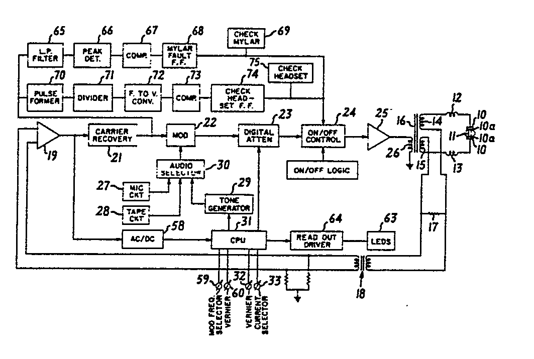
(57) @ Sound generating apparatus, for example for use as an audiometer, comprises a series
resonant circuit (12-17) having electrode terminals (10) for application to a patient
so as to include the impedance of the patient in the resonant circuit. An oscillator
(10-26) supplies to the resonant circuit a carrier signal at a high frequency determined
by the resonant circuit. A modulator (22) amplitude-modulates the carrier signal at
an audio frequency provided by an adjustable- frequency generator (27-29). An attenuator
(23) is controllable to adjust the amplitude of the carrier signal to a selected value.
An A/D converter (58, 31) generates a first digital representation of the actual amplitude
of the carrier signal, and a manually-operable selector (32, 33) provides a second
digital representation of a selected value of the carrier signal amplitude. A central
processor (31), responsive to the first and second digital representations, controls
the attenuator to maintain the amplitude of the carrier signal at the selected value.
The audio modulation frequency is similarly controlled by comparing a digital representation
of the desired frequency, as set up on a manually-operable selector (59, 60), with
a digital representation of the actual frequency. The current and modulation frequency
selectors are preset stepwise by manual rotation of rotors (40) having detents formed
by cooperating magnetic elements (46, 47) which establish rest positions corresponding
to steps to which the selector may be set. Each selector has spaced- apart segments
(42) which cooperate with a pair of optointerruptors (43, 44) to feed signals to a
logic circuit (48-57) which generates stepping pulses and pulses indicating the direction
of adjustment of the selector.
|
|
