|
(11) | EP 0 215 270 A1 |

| (12) | EUROPEAN PATENT APPLICATION |
|
|
|
|
|||||||||||||||||||||||||||
| (54) | Method and apparatus for reading recorded data by a magnetoresistive head |
| (57) Method and apparatus for magnetoresistive (MR) head biasing and output signal detection
for reading data recorded in magnetic media. The MR head may be biased by constant
current or constant voltage, and an output signal, proportional to the ratio of the
instantaneous value of the change in MR head resistance to total MR head resistance
when exposed to the magnetic field of the media, is detected. |
[0001] The present invention relates to retrieval of previously stored data, including data recorded in magnetic media and data stored in magnetic bubble memories, by a magnetoresistive (MR) read head or sensor.
[0002] An MR head is an active or parametric transducer which requires an electrical current through its resistive sensor stripe to be active. The current serves as a sensing current for converting the stripe resistance variations produced by the field, Hy, emanating from the medium into voltage variations across the stripe.
[0003] The higher the current applied to the head, the larger the readout voltage. The magnitude of the current, however, must be limited to avoid overheating the sensor stripe, and to avoid electromigration of the stripe material. This current should be provided from a low noise source to minimise noise injected into the read channel electronics.
[0004] Most existing MR head preamplifiers bias the sensor stripe of the head at a constant bias current, Ib, and detect the signal voltage, Vs, developed at the head terminals. Thus,
Vs = IbΔRh, (A)
where ΔRh is the absolute change in the head resistance, Rh, owing to the magnetic input signal, Hy, from the media being read.
[0005] Stripe height, the dimension of the sensing stripe perpendicular to the media will vary from device to device because of variations in the lapping process. Stripe height also changes as much as 50% over the life of an MR head in contact recording applications. Since both Rh and, more importantly, ΔRh are proportional to stripe height prior art preamplifiers which detect Vs of equation (A) provide different sensitivity if switched from one head to another in a multihead storage device or, in contact recording devices, as the stripe height is worn away. Similarly, different sensitivities would be encountered when switching from one sensor to another in bubble memory systems.
[0006] Moreover, Rh typically exhibits a temperature coefficient of about 0.3 to 0.5% per degree C. Thus, as temperature varies, Rh varies according to its particular temperature coefficient. The corresponding variation in ΔRh causes low frequency noise modulation of the output signal, Vs.
[0007] US-A-3,814,863 describes one prior art configurations which proposes biasing an MR head using resistors having large values with respect to the value of Rh, and an AC coupled differential voltage amplifier. In another described in US-A-4,040,113 a current source used for biasing a centre-tapped MR element and an AC coupled differential voltage amplifier for detecting the output signal produced by the head. Finally, US-A-4,191,977 describes a method of biasing a centre-tapped MR head using two inductors in series with the head and a voltage source with a DC coupled differential voltage amplifier.
[0008] Thus, the prior art teaches biasing the MR head with a constant bias current and detecting the signal produced across the head with a differential voltage amplifier. The detected signal, therefore, which is proportional to ΔRh, is sensitive to production tolerances, contact recording wear, and temperature variations.
[0009] The present invention overcomes the disadvantages of the prior art by detecting the ratio of the instantaneous value of the change in the resistance of the magneto-resistive (MR) head to the total MR head resistance.
[0010] Biasing and detection of the signal produced by an MR head, centre-tapped or not, according to the principles of the present invention may be biased by either a constant current or constant voltage source.
[0011] For a constant current configuration, MR stripe resistance, Rh, is biased by a DC current, Ib. Current variations, proportional to the instantaneous value of the relative change, ΔRh/Rh as the head detects variations in the magnetisation of the recording medium representing data, can then be applied to the input of a current sensing differential preamplifier.
[0012] In a constant DC voltage configuration instantaneous value of voltage variations produced by the MR head as it detects data recorded in a magnetic medium can be applied to the input of a voltage sensing differential preamplifier. In either the constant current or constant voltage biasing configurations only the instantaneous value of AC signal, ie the change, produced by the MR head is detected and conditioned by the differential preamplifier.
[0013] It can be seen the instantaneous value of signal produced by the MR head in these configurations is proportional to ΔRh/Rh. As both Rh and ΔRh are proportional to stripe height and to temperature changes in the same way ΔRh/Rh is independent of stripe height and temperature variations. By normalising in this way the signal produced by the MR head, variations in the value of Rh arising in such heads because of manufacturing tolerances and temperature sensitivity are therefore intrinsically corrected. It has also been found that detecting ΔRh/Rh not only corrects fully, for variations in stripe lengths, but also substantially corrects for variations in stripe thickness. Thus, in a multiple head memory device, for example, switching the signal conditioning circuitry from one head to another, does not require adjustment of the signal conditioning electronics to different levels of gain to accommodate varying detection sensitivities of the heads involved.
[0014] A number of embodiments of the invention as well as one prior art arrangement are described in the following with reference to the accompanying drawings in which:
Figure 1 is a block diagram of one typed prior art MR head biasing and output signal detection;
Figure 2A is a block diagram of one embodiment of the present invention employing constant current biasing;
Figure 2B is a block diagram of another embodiment employing constant current biasing;
Figure 3 is block diagram of an embodiment of the present invention employing a single-ended configuration;
Figure 4 is a block diagram of a further embodiment of the invention employing a pseudo-balanced configuration; and
Figure 5 is a block diagram of an embodiment of the invention employing constant voltage biasing.
[0015] Referring first to Figure 1, constant bias current, Ib, is supplied to MR head, Rh, employed, for example, in a read/write channel for reading data recorded in magnetic media. Impedances Z are the internal impedances of the bias current source. Since voltage amplifier 10 detects the head voltage, Vs, given by Equation (A) where ΔRh is the absolute change in head resistance Rh. The amplifier output, Vs, is therefore proportional to ΔRh. Hence, all other factors causing changes in Rh are also detected. Such other factors interfere with detecting only those changes in Rh which are caused by data bits recorded on a magnetic medium. The large DC voltage component produced by the constant current flowing through Rh may be removed by AC coupling capacitors at the input of amplifier 10.
[0016] Since the magnitude of ΔRh caused by a certain magnetic excitation is directly proportional to MR head resistance Rh, the output signal of amplifier 10 changes as Rh changes with temperature. The temperature coefficient of a typical MR head resistance comprising a permalloy stripe is in the range from 0.3 to 0.5% per degree C. Thus, as much as 10% change in output voltage of amplifier 10 is produced for every 20 degrees C of ambient temperature change. Since biasing and sensitivity of the MR head is also dependent on production tolerances in Rh, adjustment of the bias current for individual heads to obtain the same specified read mode sensitivity of the channel would be required.
[0017] Figure 2A illustrates an embodiment of the present invention. In this, the MR head is biased by a constant DC current, Ib. Zs is the internal source impedance of the current sources, Ib where |Zs|> >Rh. AC current variations such as noise, line hum, and the like, produced by the current sources, Ib, or supply voltage V+ and V-, are shorted out by capacitor C₁. C₁ is large enough so that,
1/2 Π Rh C₁ < < F₀,
where F₀ is the lowest frequency of interest in the signal detection channel.
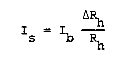
[0018] Dynamic variation of the head resistance from Rh to Rh+ΔRh produces a signal current, Is, to flow in the RhC₁ circuit. Any current sensor, such as a toroid current probe transformer can be used to detect Is. Thus, from
it follows that
If ΔRh is small with respect to Rh, then
Is ≅ IbΔRh/Rh,
and output signal, Vs, is given by
Vs ≅ KIbΔRh/Rh, (1)
where K is the sensitivity of the current sensor.
[0019] Thus, the configuration shown in Figure 2A detects a current proportional to the relative resistance change, ΔRh/Rh. Since the temperature coefficient is cancelled by this technique, Vs is substantially insensitive to temperature changes to which the MR head is subjected. Detection of a voltage proportional to relative resistance change is also insensitive to production tolerances affecting the value of Rh. Therefore, Ib need not be adjusted for uniform sensitivity from one head to another, and read mode sensitivity is independent of resistance variations arising during the manufacturing process, or owing to wear during the life of the head in contact recording applications. As shown earlier in this specification, C₁ is selected for shorting out noise current produced by the biasing network yet does not limit the bandwidth of the data signals produced by the MR head. Other interference sources at the head/media interface, which cause interference current to flow into or out of the two head terminals, are cancelled by the differential current sensing shown in Figure 2A. Therefore, this arrangement provides high rejection of common-mode interference.
[0020] In Figure 2B, Ib is derived from a reference voltage, Vr, via matched resistors, Rs. If Rs is much greater than Rh, the bias current is given by
Ib = Vr/2Rs.
[0021] Toroid, T, is a ferrite toroid having, any suitable number of recording windings, and a primary winding found by the head leads which are fed thru the toroid so that head signal current adds and common mode currents cancel. Thus, for this configuration according to equation (1), if
K = 10mv/mA, Ib = 10 mA, ΔRh/Rh = 0.5%, then Vs = 500 µv.
[0022] Referring now to Figure 3, a single-ended configuration of the present invention is shown. In this circuit, one side of Rh is grounded by C₁ at one input of differential amplifier 30. The combination of amplifier 30 and Rf is current sensing amplifier 32. Coupling capacitor C₂ removes the DC component from the output signal, Vs. Thus,
Vs = IbRf(ΔRh/Rh).
[0023] For the configuration of Figure 3, if Rh is 50 ohms and ΔRh/Rh = 0.5%, Rf is 500 ohms, C1 is 0.5 µF, C2 is 0.1 µF and amplifier 30 is a wideband amplifier, then Vs is 25 mV at F₀ = 6 kHz.
[0024] The pseudo-balanced configuration of Fig. 4 is useful in the presence of undesirable stray ground currents which may be injected into the MR head sensing stripe through the slider-to-stripe capacitance. One-half of the injected ground current, Ig, will flow through grounding resistor, Rg. The other half of Ig will flow through feedback resistor, Rf. If Rg and Rf are matched or otherwise substantially equal, the voltage developed by the flow of one-half Ig through each of these resistors will be cancelled at the amplifier output since they are of opposite phase. Thus, stray ground current, Ig, does not contaminate Vs.
[0025] For the configuration of Fig. 4, if Rh changes by an amount ΔRh, the resulting signal current is given by
Is = -Ib(ΔRh/Rh).
[0026] Current Is is supplied from feedback resistor Rf and flows through Rg to ground. Thus,
Vs = -2IbRf(ΔRh/Rh).
[0027] For the configuration of Fig. 4, with Ib = 10 mA, ΔRh/Rh = 0.5%, Is = 50 µA and Vs = -50 mV if C₁ = 0.5 µF, C₂ = 0.1 µF, Rf = 500 ohms and amplifier 30 is a wideband amplifier, such as an MC1733, manufactured by Motorola.
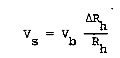
[0028] Referring now to Fig. 5, where an embodiment for constant voltage biasing of an MR head according to the present invention is shown, model reference 50 comprises a fixed current source, Ir, a resistor, Rr and capacitor, C. Voltage Vb, given by the product of Ir and Rr, provides the reference for bias voltage across MR head resistor, Rh. Since capacitor C forms a short circuit for all data frequencies, the input of voltage amplifier 70 is effectively coupled across MR head resistance, Rh. Capacitor C also shorts out all noise produced by resistor Rr. Thus, signal amplifier 70 detects and amplifies the instantaneous value of the voltage, Vs, produced by the MR head according to the relation
1. A method, employing a magnetoresistive element, for detecting magnetic fields having
encoded information, said method being characterised by the step of detecting the
ratio of the instantaneous value of the change in the resistance of the magnetoresistive
element to the total magnetoresistive element resistance.
2. A method as claimed in claim 1, comprising the steps of:
providing a current through the magnetoresistive element, said current having a constant time average value;
exposing said magnetoresistive element to the magnetic field; and
detecting current deviations from said constant time average value, said current deviations being proportional to the relative resistance change of the magnetoresistive element produced by said magnetic field.
3. A method as claimed in claim 2, wherein the step of detecting current deviations
further includes the step of amplifying the instantaneous value of the current deviations,
Is, substantially according to the relation

where Ib is the current provided by the bias current source, Rh is the absolute resistance of the magnetoresistive element, and ΔRh is the instantaneous value of the change in resistance of the magnetoresistive element in the presence of the magnetic field.
where Ib is the current provided by the bias current source, Rh is the absolute resistance of the magnetoresistive element, and ΔRh is the instantaneous value of the change in resistance of the magnetoresistive element in the presence of the magnetic field.
4. A method as claimed in claim 1, comprising the steps of:
providing a voltage to the magnetoresistive element to produce a current therethrough, said voltage having constant time average value;
exposing said magnetoresistive element to the magnetic fields; and
detecting voltage deviations from said constant time average value, said voltage deviations being proportional to the relative resistance change of the magnetoresistive element produced by said magnetic field.
5. A method as in claim 4, wherein the step of detecting voltage deviations further
includes the step of amplifying the instantaneous value of the voltage deviations,
Vs, substantially according to the relation
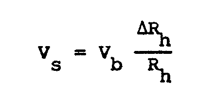
where Vb is the voltage provided by the bias voltage source, Rh is the absolute resistance of the magnetoresistive element, and ΔRh is the instantaneous value of the change in the resistance of the magnetoresistive element in the presence of the magnetic field.
where Vb is the voltage provided by the bias voltage source, Rh is the absolute resistance of the magnetoresistive element, and ΔRh is the instantaneous value of the change in the resistance of the magnetoresistive element in the presence of the magnetic field.
6. circuit for detecting magnetic fields having encoded information to produce electrical
signals representing the encoded information, the circuit comprising a magneto resistive
element and being characterised by means for detecting the ratio of the instantaneous
value of the change in the resistance of the magnetoresistive element to the total
magnetoresistive element resistance.
7. A circuit as claimed in claim 6 wherein the detecting means comprise:
a current source coupled to the magnetoresistive element to produce a current therethrough whose time average value is constant; and
detector means for detecting current deviations from said constant time average value, said deviations being proportional to the relative resistance change of the magnetoresistive element produced by exposing said magnetoresistive element to the magnetic field.
8. A circuit as in claim 7, wherein the detector means further includes amplifier
means for amplifying the instantaneous value of the current deviations, Is, substantially according to the relation
where Ib is the current provided by the bias current source, Rh is the absolute resistance of the magnetoresistive element, and ΔRh is the instantaneous value of the change in the resistance of the magnetoresistive element in the presence of the magnetic field.
where Ib is the current provided by the bias current source, Rh is the absolute resistance of the magnetoresistive element, and ΔRh is the instantaneous value of the change in the resistance of the magnetoresistive element in the presence of the magnetic field.
9. A circuit as claimed in claim 6, wherein the detecting means comprise:
a voltage source coupled to the magnetoresistive element to produce a current therethrough, said voltage source having constant time average value; and
detector means for detecting voltage deviations from said constant time average value, said deviations being proportional to the relative resistance change of the magnetoresistive element produced by exposing said magnetoresistive element to the magnetic field.
10. A circuit as claimed in claim 9, wherein the detector means further includes amplifier
means for amplifying the instantaneous value of the voltage deviations, Vs, substantially according to the relation
where Vb is the voltage provided by the bias voltage source, Rh is the absolute resistance of the magnetoresistive element, and ΔRh is the instantaneous value of the change in the resistance of the magnetoresistive element in the presence of the magnetic field.
where Vb is the voltage provided by the bias voltage source, Rh is the absolute resistance of the magnetoresistive element, and ΔRh is the instantaneous value of the change in the resistance of the magnetoresistive element in the presence of the magnetic field.