|
(11) | EP 0 227 094 A2 |

| (12) | EUROPEAN PATENT APPLICATION |
|
|
|
|
|||||||||||||||||||||||||||
| (54) | High molecular weight polycarbonate receiving layer used in thermal dye transfer |
| (57) A dye-receiving element for thermal dye transfer comprises a support having thereon
a dye image-receiving layer comprising a polycarbonate, such as a bisphenol A polycarbonate,
having a number average molecular weight of at least 25,000. Use of this material
reduces an undesirable relief image which otherwise tends to be obtained. |
[0001] This invention relates to dye-receiving elements used in thermal dye transfer, and more particularly to the use of a support having thereon a dye image-receiving layer comprising a polycarbonate having a number average weight of at least 25,000.
[0002] In recent years, thermal transfer systems have been developed to obtain prints from pictures which have been generated electronically from a color video camera. According to one way of obtaining such prints, an electronic picture is first subjected to color separation by color filters. The respective color-separated images are then converted into electrical signals. These signals are then operated on to produce cyan, magenta and yellow electrical signals. These signals are then transmitted to a thermal printer. To obtain the print, a cyan, magenta or yellow dye-donor element is placed face-to-face with a dye-receiving element. The two are then inserted between a thermal printing head and a platen roller. A line-type thermal printing head is used to apply heat from the back of the dye-donor sheet. The thermal printing head has many heating elements and is heated up sequentially in response to the cyan, magenta and yellow signals. The process is then repeated for the other two colors. A color hard copy is thus obtained which corresponds to the original picture viewed on a screen.
[0003] In Japanese laid open publication number 19,138/85, an image-receiving element for thermal dye transfer printing is disclosed. The dye image-receiving layer disclosed comprises a polycarbonate containing a plasticizer. The specific polycarbonates employed have a relatively low average molecular weight.
[0004] While polycarbonate is a desirable material for a dye-image receiving layer because of its effective dye compatibility and receptivity, there is a problem with employing the specific polycarbonates disclosed in the above reference since they have been found to be quite susceptible to thermal surface deformation. This occurs because of the heating and pressure contact within the nip between the thermal print head and a rubber roller, which causes the raised/depressed pattern of the thermal print head to be embossed upon the receiving layer. Additional distortion of the receiving layer may also occur from differential heating. The rough relief image on the surface of the receiving layer results in an undesirable differential gloss and could also result in a maximum density loss in extreme cases.
[0005] It is an object of this invention to provide a polycarbonate dye image-receiving layer which does not have the disadvantages discussed above, and in which less permanent surface deformation occurs, producing more pleasing prints of uniform gloss free from visible relief images.
[0006] These and other objects are achieved in accordance with this invention which comprises a dye-receiving element for thermal dye transfer which comprises a support having thereon a polycarbonate dye image-receiving layer, characterized in that the polycarbonate has a number average molecular weight of at least 25,000.
[0007] The term "polycarbonate" as used herein means a polyester of carbonic acid and glycol or a divalent phenol. Examples of such glycols or divalent phenols are p-xylyene glycol, 2,2-bis(4-oxyphenyl)propane, bis(4-oxyphenyl)methane, 1,1-bis(4-oxyphenyl)ethane, 1,1-bis(oxyphenyl)butane, 1,1-bis(oxyphenyl)cyclohexane, 2,2-bis(oxyphenyl)butane, etc.
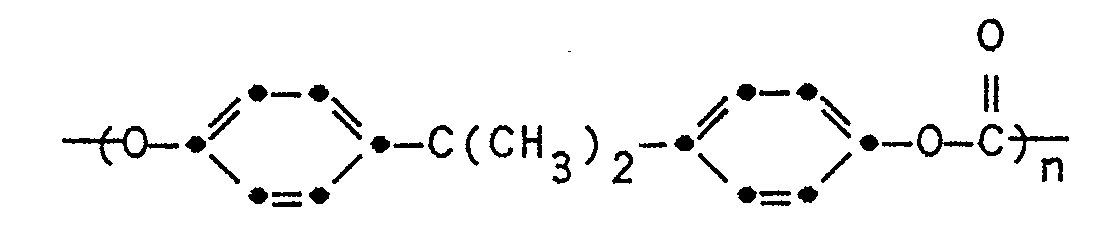
[0008] In a preferred embodiment of the invention, the polycarbonate is a bisphenol A polycarbonate. In another preferred embodiment of the invention, the bisphenol A polycarbonate comprises recurring units having the formula
wherein n is from 100 to 500.
[0009] Examples of such polycarbonates include: General Electric Lexan® Polycarbonate Resin #ML-4735 (Number average molecular weight app. 36,000), and Bayer AG, Makrolon #5705® (Number average molecular weight app. 58,000).
[0010] The polycarbonate employed in the dye image-receiving layer may be present in any amount which is effective for the intended purpose. In general, good results have been obtained at a total concentration of from 1 to 5 g/m².
[0011] The support for the dye-receiving element of the invention may be a transparent film such as a poly(ether sulfone), a polyimide, a cellulose ester such as cellulose acetate, a poly(vinyl alcohol-coacetal) or a poly(ethylene terephthalate). The support for the dye-receiving element may also be reflective such as baryta-coated paper, white polyester (polyester with white pigment incorporated therein), an ivory paper, a condenser paper or a synthetic paper such as duPont Tyvek®. In a preferred embodiment, polyester with a white pigment incorporated therein is employed. It may be employed at any thickness desired, usually from 50 µm to 1000 µm.
[0012] A dye-donor element that is used with the dye-receiving element of the invention comprises a support having thereon a dye layer. Any dye can be used in such a layer provided it is transferable to the dye image-receiving layer of the dye-receiving element of the invention by the action of heat. Especially good results have been obtained with sublimable dyes such as
or any of the dyes disclosed in U.S. Patent 4,541,830. The above dyes may be employed singly or in combination to obtain a monochrome. The dyes may be used at a coverage of from 0.05 to 1 g/m² and are preferably hydrophobic.
[0013] The dye in the dye-donor element is dispersed in a polymeric binder such as a cellulose derivative, e.g., cellulose acetate hydrogen phthalate, cellulose acetate, cellulose acetate propionate, cellulose acetate butyrate, cellulose triacetate; a polycarbonate; poly(styrene-co-acrylonitrile), a poly(sulfone) or a poly(phenylene oxide). The binder may be used at a coverage of from 0.1 to 5 g/m².
[0014] The dye layer of the dye-donor element may be coated on the support or printed thereon by a printing technique such as a gravure process.
[0015] Any material can be used as the support for the dye-donor element provided it is dimensionally stable and can withstand the heat of the thermal printing heads. Such materials include polyesters such as poly(ethylene terephthalate); polyamides; polycarbonates; glassine paper; condenser paper; cellulose esters; fluorine polymers; polyethers; polyacetals; polyolefins; and polyimides. The support generally has a thickness of from 2 to 30 µm. It may also be coated with a subbing layer, if desired.
[0016] A dye-barrier layer comprising a hydrophilic polymer may also be employed in the dye-donor element between its support and the dye layer which provides improved dye transfer densities.
[0017] The reverse side of the dye-donor element may be coated with a slipping layer to prevent the printing head from sticking to the dye-donor element. Such a slipping layer would comprise a lubricating material such as a surface active agent, a liquid lubricant, a solid lubricant or mixtures thereof, with or without a polymeric binder.
[0018] As noted above, dye-donor elements are used to form a dye transfer image. Such a process comprises imagewise-heating a dye-donor element and transferring a dye image to a dye-receiving element as described above to form the dye transfer image.
[0019] The dye-donor element employed in certain embodiments of the invention may be used in sheet form or in a continuous roll or ribbon. If a continuous roll or ribbon is employed, it may have only one dye thereon or may have alternating areas of different dyes such as cyan, magenta, yellow, black, etc., as dislcosed in U. S. Patent 4,541,830.
[0020] In a preferred embodiment of the invention, a dye-donor element is employed which comprises a poly(ethylene terephthalate) support coated with sequential repeating areas of cyan, magenta and yellow dye, and the above process steps are sequentially performed for each color to obtain a three-color dye transfer image. Of course, when the process is only performed for a single color, then a monochrome dye transfer image is obtained.
[0021] Thermal printing heads which can be used to transfer dye from the dye-donor elements employed in the invention are available commercially. There can be employed, for example, a Fujitsu Thermal Head (FTP-040 MCSOO1), a TDK Thermal Head F415 HH7-1089 or a Rohm Thermal Head KE 2008-F3.
[0022] A thermal dye transfer assemblage using the invention comprises
a) a dye-donor element as described above, and
b) a dye-receiving element as described above,
the dye-receiving element being in a superposed relationship with the dye-donor element so that the dye layer of the donor element is in contact with the dye image-receiving layer of the receiving element.[0023] The above assemblage comprising these two elements may be preassembled as an integral unit when a monochrome image is to be obtained. This may be done by temporarily adhering the two elements together at their margins. After transfer, the dye-receiving element is then peeled apart to reveal the dye transfer image.
[0024] When a three-color image is to be obtained, the above assemblage is formed on three occasions during the time when heat is applied by the thermal printing head. After the first dye is transferred, the elements are peeled apart. A second dye-donor element (or another area of the donor element with a different dye area) is then brought in register with the dye-receiving element and the process repeated. The third color is obtained in the same manner.
Example
[0026] A magenta dye-donor element was prepared by coating the following layers in the order recited on a 6 µm poly(ethylene terephthalate) support:
1) dye-barrier layer of gelatin nitrate (gelatin, cellulose nitrate, and salicylic acid in approximately 20:5:2 weight ratio in a solvent of acetone, methanol and water) (0.11 g/m²), and
2) dye layer containing the following magenta dye (0.17 g/m²), 11 mg/m² 3M FC-431® surfactant, duPont DLX-6000® poly(tetrafluoroethylene) micropowder (16 mg/m²) and cellulose acetate propionate (2.5% acetyl, 45% propionyl) (0.37 g/m²) coated from a butanone and cyclopentanone solvent mixture.
On the back side of the element was coated a typical slipping layer.Magenta Dye
[0028] Dye-receiving elements were prepared by coating the polycarbonates as listed in Table 1 (2.9 g/m²) and 41 mg/m² of 3M FC-431® surfactant from a dichloromethane/trichloroethylene solvent mixture on an ICI Melinex 990® "white polyester" support.
[0029] A second set of dye-receiving elements was prepared as above except that it contained 0.29 g/m² di-n-butyl phthalate as a plasticizer.
[0030] The dye side of each dye-donor element strip 1.25 inches (30 mm) wide was placed in contact with the dye image-receiving layer of the dye-receiver element of the same width. The assemblage was fastened in the jaws of a stepper motor driven pulling device. The assemblage was laid on top of a 0.55 (14 mm) diameter rubber roller and a TDK Thermal Head (No. L-133) and was presssed with a spring at a force of 8.0 pounds (3.6 kg) against the dye-donor element side of the assemblage pushing it against the rubber roller.
[0031] The imaging electronics were activated causing the pulling device to draw the assemblage between the printing head and roller at 0.123 inches/sec (3.1 mm/sec). Coincidentally, the resistive elements in the thermal print head were pulse heated at approximately 8 msec to generate a maximum density image. The voltage supplied to the print head was approximately 22v representing approximately 1.5 watts/dot (12 mjoules/dot) for maximum power.
[0033] Surface deformation was measured using a Gould Microtopographer. Three dimensional topographic representations of the maximum density image surfaces were generated by driving a 0.0001 inch radius diamond stylus at a 45 degree angle relative to the print head direction. The data was analyzed by a Hewlett-Packard computer program to give an average surface roughness in microinches of projection. The following results were obtained:
Polycarbonates:
[0035] Polycarbonate A was Scientific Polymer Products Inc., Catalog #035 (number average molecular weight approximately 24,000), n calc. approximately 95. Polycarbonate B was General Electric Lexan® Polycarbonate Resin #ML-4735 (number average molecular weight approximately 36,000), n calc. approximately 140. Polycarbonate C was Bayer AG Makrolon #5705® (number average molecular weight approximately 58,000), n calc. approximately 230.
[0036] The above data indicate that the three polycarbonate receivers all gave equivalent maximum densities. However, the surface roughness decreases significantly (less deformation) as the polycarbonates of the invention were used which had a higher molecular weight. The same relationship was also observed with the plasticized samples. Thus, a polycarbonate having a number average molecular weight above 25,000 is necessary in order to minimize surface deformations.
1. A dye-receiving element for thermal dye transfer comprising a support having thereon
a polycarbonate dye image-receiving layer, characterized in that said polycarbonate
has a number average molecular weight of at least 25,000.
2. The element of Claim 1 characterized in that said polycarbonate is a bisphenol
A polycarbonate.
3. The element of Claim 2 characterized in that said bisphenol A polycarbonate comprises
recurring units having the formula
wherein n is from 100 to 500.
wherein n is from 100 to 500.
4. The element of any of Claims 1 to 3 characterized in that said support is poly(ethylene
terephthalate) having a white pigment incorporated therein.
5. A thermal dye transfer assemblage comprising:
a) a dye-donor element comprising a support having thereon a dye layer, and
b) a dye-receiving element comprising a support having thereon a polycarbonate dye image-receiving layer,
said dye-receiving element being in a superposed relationship with said dye-donor element so that said dye layer is in contact with said dye image-receiving layer,
characterized in that said polycarbonate has a number average molecular weight of at least 25,000.
6. The assemblage of Claim 5 characterized in that said polycarbonate is a bisphenol
A polycarbonate.
7. The assemblage of Claim 6 characterized in that said bisphenol A polycarbonate
comprises recurring units having the formula
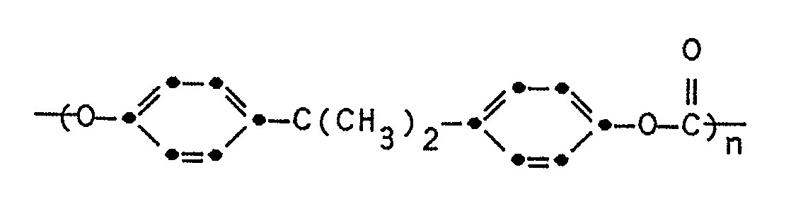
wherein n is from 100 to 500.
wherein n is from 100 to 500.
8. The assemblages of any of Claims 5 to 7 characterized in that said support of said
dye-receiving element is poly-(ethylene terephthalate) having a white pigment incorporated
therein.