|
(11) | EP 0 227 095 A2 |

| (12) | EUROPEAN PATENT APPLICATION |
|
|
|
|
|||||||||||||||||||||||||||
| (54) | Magenta dye-donor element used in thermal dye transfer |
| (57) A magenta dye-donor element for thermal dye transfer comprises a support having thereon
a magenta dye dispersed in a polymeric binder, the magenta dye comprising a substituted
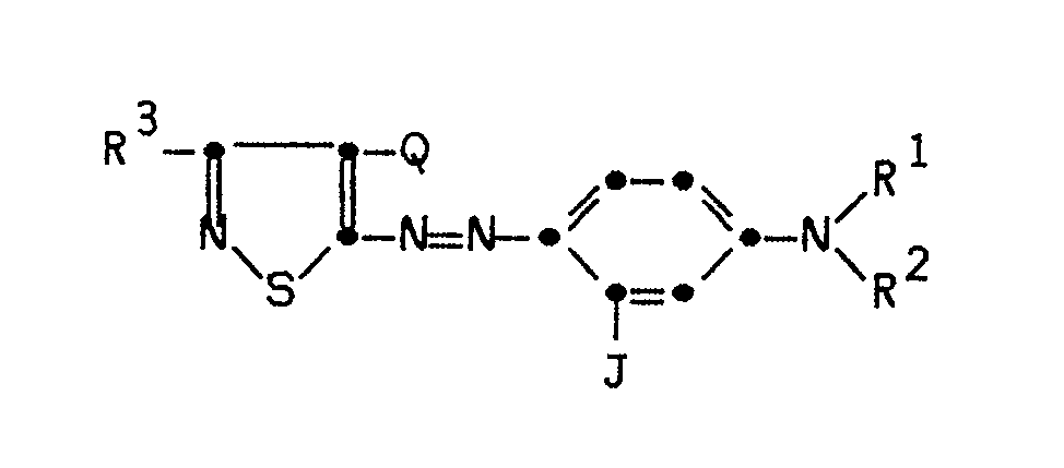
5-arylazoisothiazole. In a preferred embodiment, the magenta dye has the formula: wherein R¹ and R² may each independently be hydrogen, alkyl, allyl, cycloalkyl or aryl; or R¹ and R² may be taken together to form a ring; or R¹ or R² may be part of a 5- or 6-membered heterocyclic ring; R³ may be hydrogen, alkyl, aryl, alkylthio or halogen; J may be alkyl, aryl or NHA, where A is an acyl or sulfonyl radical; and Q may be cyano, thiocyanato, alkylthio or alkoxycarbonyl. |
[0001] This invention relates to magenta dye-donor elements used in thermal dye transfer which have good hue and dye stability.
[0002] In recent years, thermal transfer systems have been developed to obtain prints from pictures which have been generated electronically from a color video camera. According to one way of obtaining such prints, an electronic picture is first subjected to color separation by color filters. The respective color-separated images are then converted into electrical signals. These signals are then operated on to produce cyan, magenta and yellow electrical signals. These signals are then transmitted to a thermal printer. To obtain the print, a cyan, magenta or yellow dye-donor element is placed face-to-face with a dye-receiving element. The two are then inserted between a thermal printing head and a platen roller. A line-type thermal printing head is used to apply heat from the back of the dye-donor sheet. The thermal printing head has many heating elements and is heated up sequentially in response to the cyan, magenta and yellow signals. The process is then repeated for the other two colors. A color hard copy is thus obtained which corresponds to the original picture viewed on a screen.
[0003] Japanese Patent Publication 60/030394 relates to magenta thiadiazole dyes used in thermal transfer. These compounds have some structural similarity to those of the invention.
[0004] There is a problem with many of these dyes proposed for use in thermal dye transfer printing in that they do not have adequate stability to light. Others do not have good hue.
[0005] It is an object of this invention to provide dyes which have good light stability and have improved hues.
[0006] These and other objects are achieved in accordance with this invention which comprises a magenta dye-donor element for thermal dye transfer comprising a magenta dye dispersed in a polymeric binder, characterized in that the magenta dye comprises a substituted 5-arylazoisothiazole.
[0007] In a preferred embodiment of the invention, the substituted 5-arylazoisothiazole has the following formula:
wherein:
R¹ and R² may each independently be hydrogen; substituted or unsubstituted alkyl or allyl of from 1 to 6 carbon atoms such as methyl, ethyl, propyl, isopropyl, butyl, pentyl, hexyl or such alkyl groups substituted with hydroxy, acyloxy, alkoxy, aryl, cyano, acrylamido, halogen, etc.; substituted or unsubstituted cycloalkyl of from 5 to 7 carbon atoms such as cyclopentyl, cyclohexyl, p-methylcyclohexyl, etc.; or substituted or unsubstituted aryl of from 5 to 10 carbon atoms such as phenyl, p-tolyl, m-chlorophenyl, p-methoxyphenyl, m-bromophenyl, o-tolyl, etc.; or R¹ and R² may be taken together to form a ring such as pentamethylene, hexamethylene, etc.; or a 5- or 6-membered heterocyclic ring may be formed with R¹ or R², the nitrogen to which R¹ or R² is attached, and either carbon atom ortho to the carbon attached to the nitrogen atom;
R³ may be hydrogen; substituted or unsubstituted alkyl of from 1 to 6 carbon atoms such as those listed above for R¹ and R²; substituted or unsubstituted aryl of from 5 to 10 carbon atoms such as phenyl, p-tolyl, m-chlorophenyl, p-methoxyphenyl, m-bromophenyl, o-tolyl, etc.; alkylthio or halogen;
J may be substituted or unsubstituted alkyl of from 1 to 6 carbon atoms or substituted or unsubstituted aryl of from 5 to 10 carbon atoms such as such as those listed above for R₃; or NHA, where A is an acyl or sulfonyl radical such as formyl, lower alkanoyl, aroyl, cyclohexylcarbonyl, lower alkoxycarbonyl, aryloxycarbonyl, lower alkylsulfonyl, cyclohexylsulfonyl, arylsulfonyl, carbamoyl, lower alkylcarbamoyl, arylcarbamoyl, sulfamoyl, lower alkylsulfamoyl, furoyl, etc; and
Q may be cyano, thiocyanato, alkylthio or alkoxycarbonyl.
[0008] The compounds used in the invention may be prepared by established synthetic procedures such as are described in Example 2 of U.S. Patent 3,770,370 of Weaver et al.
[0009] In a preferred embodiment of the invention, R³ is methyl and Q is CN. In another preferred embodiment of the invention, J is -NHCOCH₃. In still another preferred embodiment of the invention, R₁ is C₂H₅ and R² is CH₂C₆H₅, cyclohexyl or CH₂CH₂O₂CCH₃. In yet another preferred embodiment of the invention, R¹ and R² are each n-C₃H₇ or C₂H₅.
[0011] A dye-barrier layer may be employed in the dye-donor elements of the invention to improve the density of the transferred dye.
[0012] The dye in the dye-donor element of the invention is dispersed in a polymeric binder such as a cellulose derivative, e.g., cellulose acetate hydrogen phthalate, cellulose acetate, cellulose acetate propionate, cellulose acetate butyrate, cellulose triacetate; a polycarbonate; poly(styrene-co-acrylonitrile), a poly(sulfone) or a poly(phenylene oxide). The binder may be used at a coverage of from 0.1 to 5 g/m².
[0013] The dye layer of the dye-donor element may be coated on the support or printed thereon by a printing technique such as a gravure process.
[0014] Any material can be used as the support for the dye-donor element of the invention provided it is dimensionally stable and can withstand the heat of the thermal printing heads. Such materials include polyesters such as poly(ethylene terephthalate); polyamides; polycarbonates; glassine paper; condenser paper; cellulose esters; fluorine polymers; polyethers; polyacetals; polyolefins; and polyimides. The support generally has a thickness of from 2 to 30 µm. It may also be coated with a subbing layer, if desired.
[0015] The reverse side of the dye-donor element may be coated with a slipping layer to prevent the printing head from sticking to the dye-donor element. Such a slipping layer would comprise a lubricating material such as a surface active agent, a liquid lubricant, a solid lubricant or mixtures thereof, with or without a polymeric binder.
[0016] The dye-receiving element that is used with the dye-donor element of the invention usually comprises a support having thereon a dye image-receiving layer. For example, the support may be a transparent film such as poly(ethylene terephthalate) or may also be reflective such as baryta-coated paper or white polyester (polyester with white pigment incorporated therein).
[0017] The dye image-receiving layer may comprise, for example, a polycarbonate, a polyurethane, a polyester, polyvinyl chloride, poly(styrene-co-acrylonitrile), poly(caprolactone) or mixtures thereof.
[0018] As noted above, the dye-donor elements of the invention are used to form a dye transfer image. Such a process comprises imagewise-heating a dye-donor element as described above and transferring a dye image to a dye-receiving element to form the dye transfer image.
[0019] The dye-donor element of the invention may be used in sheet form or in a continuous roll or ribbon. If a continuous roll or ribbon is employed, it may have only the magenta dye thereon as described above or may have alternating areas of other different dyes, such as sublimable cyan and/or yellow and/or black or other dyes.
[0020] In a preferred embodiment of the invention, the dye-donor element comprises a poly(ethylene terephthalate) support coated with sequential repeating areas of cyan, yellow and the magenta dye as described above, and the above process steps are sequentially performed for each color to obtain a three-color dye transfer image. Of course, when the process is only performed for a single color, then a monochrome dye transfer image is obtained.
[0021] Thermal printing heads which can be used to transfer dye from the dye-donor elements of the invention are available commercially. There can be employed, for example, a Fujitsu Thermal Head (FTP-040 MCS001), a TDK Thermal Head F415 HH7-1089 or a Rohm Thermal Head KE 2008-F3.
[0022] A thermal dye transfer assemblage using the invention comprises
a) a dye-donor element as described above, and
b) a dye-receiving element as described above,
the dye-receiving element being in a superposed relationship with the dye-donor element so that the dye layer of the donor element is in contact with the dye image-receiving layer of the receiving element.
[0023] The above assemblage comprising these two elements may be preassembled as an integral unit when a monochrome image is to be obtained. This may be done by temporarily adhering the two elements together at their margins. After transfer, the dye-receiving element is then peeled apart to reveal the dye transfer image.
[0024] When a three-color image is to be obtained, the above assemblage is formed on three occasions during the time when heat is applied by the thermal printing head. After the first dye is transferred, the elements are peeled apart. A second dye-donor element (or another area of the donor element with a different dye area) is then brought in register with the dye-receiving element and the process repeated. The third color is obtained in the same manner.
Examples
Example 1
[0026] A) A magenta dye-donor element was prepared by coating the following layers in the order recited on a 6 µm poly(ethylene terephthalate) support:
1) Dye-barrier layer of gelatin nitrate (gelatin, cellulose nitrate, and salicylic acid in approximately 20:5:2 weight ratio in a solvent of acetone, methanol and water) (0.20 g/m²), and
2) Dye layer containing a magenta dye as identified in the following Table 1 (0.17-0.22 g/m²) in cellulose acetate hydrogen phthalate (0.30-0.33 g/m²) coated from an acetone/2-butanone/cyclohexanone solvent.
On the back side of the element, a slipping layer of poly(vinyl stearate) (0.31 g/m²) in cellulose acetate butyrate (0.55 g/m²) was coated from tetrahydrofuran solvent.
[0027] Dye-receiving elements were prepared by coating a solution of Makrolon 5705® (Bayer AG Corporation) polycarbonate resin (2.9 g/m²) in a methylene chloride and trichloroethylene solvent mixture on an ICI Melinex 990® white polyester support for density evaluations or on a transparent poly(ethylene terephthalate) film support for spectral absorption evaluations.
[0028] The dye side of the dye-donor element strip 0.75 inches (19 mm) wide was placed in contact with the dye image-receiving layer of the dye-receiver element of the same width. The assemblage was fastened in the jaws of a stepper motor driven pulling device. The assemblage was laid on top of a 0.55 (14 mm) diameter rubber roller and a Fujitsu Thermal Head (FTP-040MCS001) and was pressed with a spring at a force of 3.5 pounds (1.6 kg) against the dye-donor element side of the assemblage pushing it against the rubber roller.
[0029] The imaging electronics were activated causing the pulling device to draw the assemblage between the printing head and roller at 0.123 inches/sec (3.1 mm/sec). Coincidentally, the resistive elements in the thermal print head were heated at 0.5 msec increments from 0 to 4.5 msec to generate a graduated density test pattern. The voltage supplied to the print head was approximately 19 v representing approximately 1.75 watts/dot. Estimated head temperature was 250-400°C.
[0030] The dye-receiving element was separated from the dye-donor element and the Status A green reflection density of the step image was read. The image was then subjected to "HID-fading": 4 days, 50 kLux, 5400°K, 32°C, approximately 25% RH. The density loss at a density near 1.0 was calculated.
[0031] The following dye stability data were obtained:
Use of the compounds in accordance with the invention showed superior light stability as compared to a variety of control dyes.
[0032] The light absorption spectra from 400 to 700 nm were also obtained after transfer of an area of the dye to the transparent support receiver in the manner indicated above. From a computer normalized 1.0 density curve, the λ-max, and HBW (half-band width =width of the dye absorption envelope at one-half the maximum dye density) were calculated. The following results were obtained:
[0033] The dyes of the invention are of good magenta hue and all have λ-max in the desired region of 545 to 560 nm. The control dyes are all too red (too much absorption on the short wavelength side). The control dye 3 with relatively good dye stability was the poorest for hue.
Example 2
[0034] A magenta dye-donor element was prepared by coating the following layers in the order recited on a 6 µm poly(ethylene terephthalate) support:
1) Dye-barrier layer of poly(acrylic) acid (0.16 g/m²) coated from water, and
2) Dye layer containing a magenta dye as identified in the following Table 4 (0.41 mmoles/m²) (0.17-0.20 g/m²), a cellulose acetate binder (40% acetyl) at a weight equal to 1.5X that of the dye, and FC-431® 3M Corp. (2.2 mg/m²), coated from a 2-butanone/cyclohexanone solvent mixture.
On the back side of the element was coated a typical slipping layer.
[0036] The dye side of the dye-donor element strip 0.75 inches (19 mm) wide was placed in contact with the dye image-receiving layer of the dye-receiver element of the same width. The assemblage was fastened in the jaws of a stepper motor driven pulling device. The assemblage was laid on top of a 0.55 (14 mm) diameter rubber roller and a TDK Thermal Head (No. L-133) and was pressed with a spring at a force of 8.0 pounds (3.6 kg) against the dye-donor element side of the assemblage pushing it against the rubber roller.
[0037] The imaging electronics were activated causing the pulling device to draw the assemblage between the printing head and roller at 0.123 inches/sec (3.1 mm/sec). Coincidentally, the resistive elements in the thermal print head were pulse-heated at increments from 0 to 8.3 msec to generate a graduated density test pattern. The voltage supplied to the print head was approximately 22v representing approximately 1.5 watts/dot (12 mjoules/dot) for maximum power.
[0038] The dye-receiving element was separated from the dye-donor element and dye stability and light absorption data were obtained as described in Example 1 except that the dye stability data was calculated as percent density loss from a mid-scale density near 1.0. The following results were obtained:
1. A magenta dye-donor element for thermal dye transfer comprising a support having
thereon a dye layer comprising a magenta dye dispersed in a polymeric binder, characterized
in that said magenta dye comprises a substituted 5-arylazoisothiazole.
2. The element of Claim 1 characterized in that said magenta dye has the formula:
wherein R¹ and R² may each independently be hydrogen, substituted or unsubstituted alkyl or allyl of from 1 to 6 carbon atoms, substituted or unsubstituted cycloalkyl of from 5 to 7 carbon atoms, substituted or unsubstituted aryl of from 5 to 10 carbon atoms; or R¹ and R² may be taken together to form a ring; or a 5- or 6-membered heterocyclic ring may be formed with R¹ and R², the nitrogen to which R¹ and R² is attached, and either carbon atom ortho to the carbon attached to said nitrogen atom;
R³ may be hydrogen, substituted or unsubstituted alkyl of from 1 to 6 carbon atoms, substituted or unsubstituted aryl of from 5 to 10 carbon atoms, alkylthio or halogen;
J may be substituted or unsubstituted alkyl of from 1 to 6 carbon atoms, substituted or unsubstituted aryl of from 5 to 10 carbon atoms or NHA, where A is an acyl or sulfonyl radical; and
Q may be cyano, thiocyanato, alkylthio or alkoxycarbonyl.
3. The element of Claim 2 characterized in that R³ is methyl and Q is CN.
4. The element of Claim 2 characterized in the J is -NHCOCH₃.
5. The element of Claim 2 characterized in that R¹ is C₂H₅ and R² is CH₂C₆H₅, cyclohexyl
or CH₂CH₂O₂CCH₃.
6. The element of Claim 2 characterized in that R¹ and R² are each n-C₃H₇ or C₂H₅.
7. The element of Claim 1 characterized in that a dye-barrier layer is located between
said dye layer and said support.
8. The element of Claim 1 characterized in that the side of the support opposite the
side bearing said dye layer is coated with a slipping layer comprising a lubricating
material.
9. The element of Claim 1 characterized in that said support comprises poly(ethylene
terephthalate).
10. The element of Claim 1 characterized in that said dye layer comprises sequential
repeating areas of cyan, yellow and said magenta dye.