| (19) |
 |
|
(11) |
EP 0 105 200 B1 |
| (12) |
EUROPEAN PATENT SPECIFICATION |
| (45) |
Mention of the grant of the patent: |
|
11.11.1987 Bulletin 1987/46 |
| (22) |
Date of filing: 31.08.1983 |
|
| (51) |
International Patent Classification (IPC)4: A63G 31/00 |
|
| (54) |
Amusement apparatus
Vergnügungsgerät
Dispositif de divertissement
|
| (84) |
Designated Contracting States: |
|
DE FR GB IT |
| (30) |
Priority: |
30.09.1982 US 431847
|
| (43) |
Date of publication of application: |
|
11.04.1984 Bulletin 1984/15 |
| (71) |
Applicant: Sassak, John J. |
|
Livonia
Michigan 48150 (US) |
|
| (72) |
Inventor: |
|
- Sassak, John J.
Livonia
Michigan 48150 (US)
|
| (74) |
Representative: Schaumburg, Thoenes & Thurn |
|
Mauerkircherstrasse 31
81679 München
81679 München (DE) |
|
| |
|
| Note: Within nine months from the publication of the mention of the grant of the European
patent, any person may give notice to the European Patent Office of opposition to
the European patent
granted. Notice of opposition shall be filed in a written reasoned statement. It shall
not be deemed to
have been filed until the opposition fee has been paid. (Art. 99(1) European Patent
Convention).
|
[0001] This invention is related to an amusement apparatus for raising or lowering a passenger
comprising a hollow passenger-holding body, a base having a top opening and a seat
adapted to receive the body, the base having a second, lower opening.
[0002] Motion simulators employed in amusement devices and flight simulators usually comprise
a hollow body or frame for receiving a passenger. The body is then moved through a
series of motions to simulate flight through the air. Such devices are commonly used
for training aircraft personnel. Other devices are used as amusement devices with
a video screen that presents images consistent with the simulated flight.
[0003] The frame is mounted in a cradle or base and rocked or otherwise horizontally moved,
usually without any substantial vertical displacement. One device in which the body
is horizontally moved is illustrated in US-A-2,344,454, disclosing a spherical shell
floating on a body of water with controls for rotating the shell about its center.
[0004] According to the present invention an apparatus of the kind mentioned above is characterized
by a source of air and means for directing a jet of air upwardly through the lower
opening beneath the body to raise it such that it is supported on a cushion of air.
[0005] In the preferred embodiment of the invention, which will be described in greater
detail, the body is mounted in a semi-spherical base having an upright, transparent,
tubular conduit mounted above the base so that the body is raised to an elevated position
in the tube. A movable weight is mounted within the body so that the passenger can
revolve the body by displacing the weight from the body's center of gravity.
[0006] Still further objects and advantages of the invention will become readily apparent
to those skilled in the art to which the invention pertains upon reference to the
following detailed description.
[0007] The description refers to the accompanying drawings in which like reference characters
refer to like parts throughout the several views, and in which:
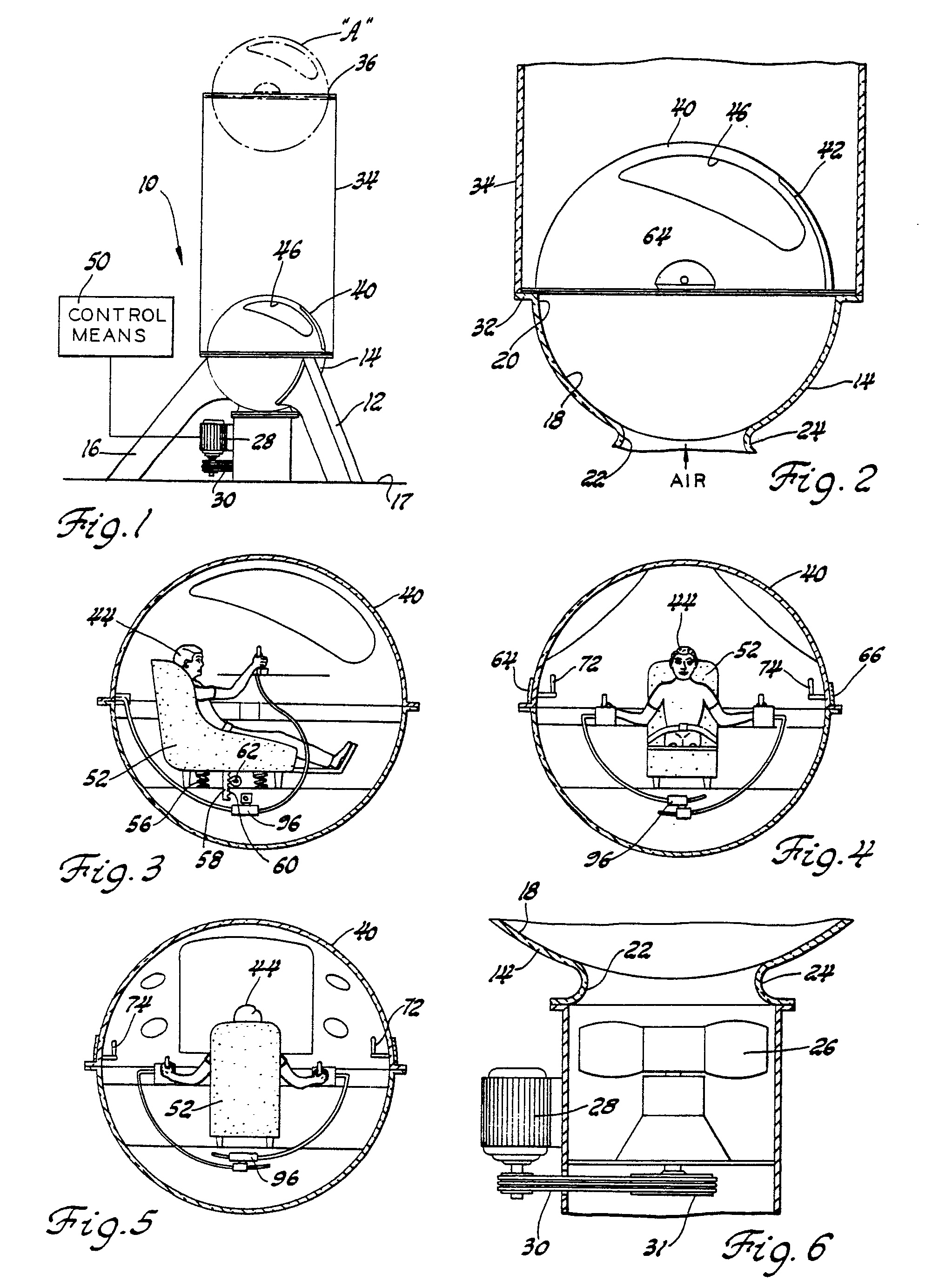
Figure 1 is a partially schematic view showing an amusement device illustrating the
preferred embodiment of the invention;
Figure 2 is a sectional view of the body slightly raised above the base;
Figure 3 is a fragmentary view illustrating the internal arrangement of the body;
Figure 4 is another internal view of the body illustrating the weight operated controls;
Figure 5 is still another internal view of the body showing the control arrangement
and the simulated controls;
Figure 6 is sectional view of the turbine housing;
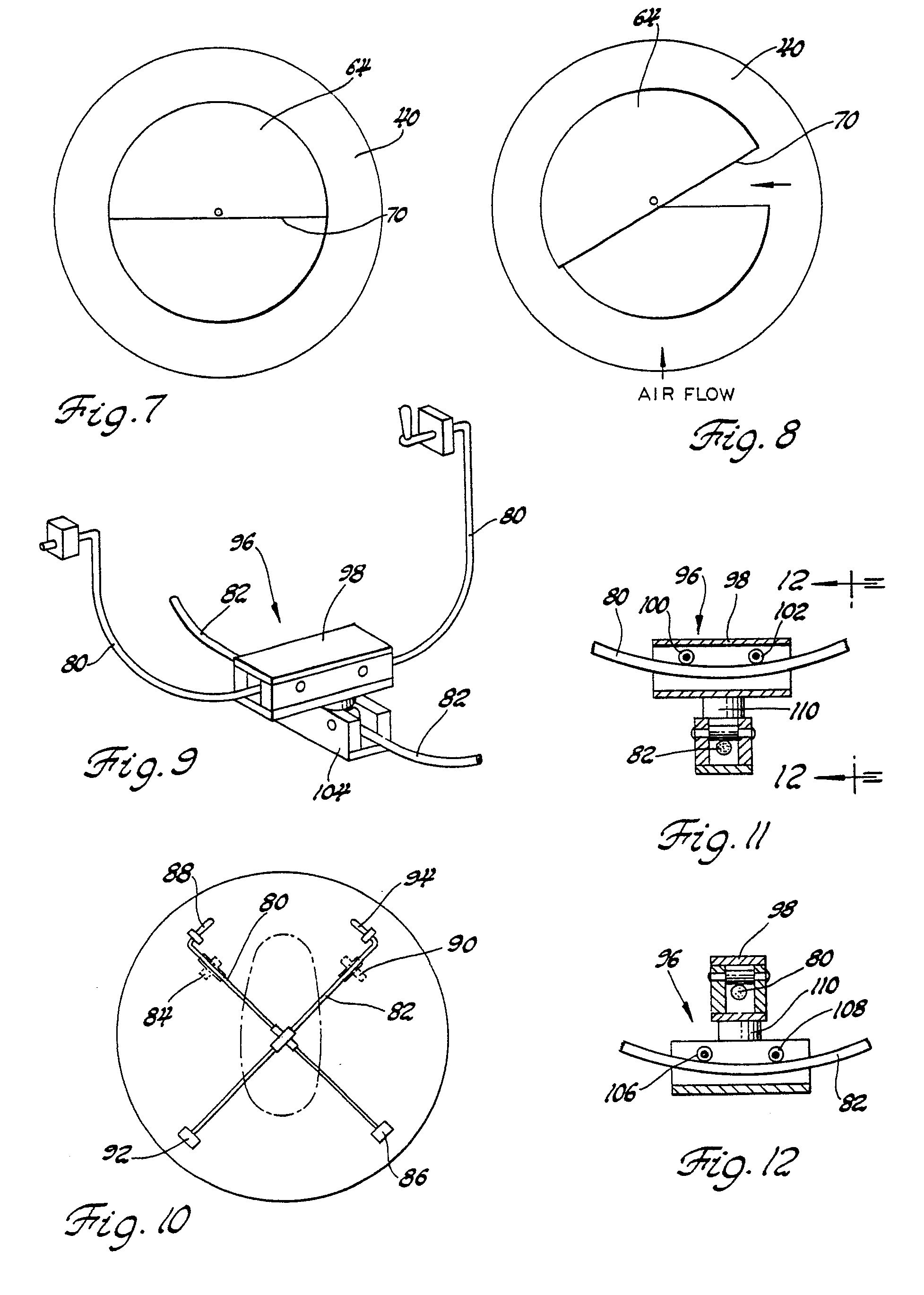
Figure 7 is a view of the louver used for revolving the body about the tube's axis;
Figure 8 is a view of the louver in another position;
Figure 9 is a view of the system for controlling the position of the weight;
Figure 10 is a plan schematic view of the weight control system;
Figure 11 is a fragmentary view showing the manner in which the weight is connected
to the guide rods; and
Figure 12 is a view as seen along lines 12-12 of Figure 11.
[0008] Referring to the drawings, Figure 1 illustrates a preferred amusement device 10 comprising
base means 12. Base means 12 has a semi-spherical base member 14 supported by legs
16 above ground 17. Base member 14 has a generally spherical seat 18, an upper opening
20 and a lower opening 22. A turbine housing 24 is mounted beneath opening 22.
[0009] Referring to Figures 1 and 6, turbine means 26 is mounted within the housing. A motor
28 is mounted on the housing and connected by belt means 30 for driving the turbine
to direct a flow of air through opening 22 into base member 14.
[0010] Belt means 30 includes a sheave 31 weighted so as to form a flywheel in the event
power is terminated for some reason to motor 28 so that the turbine continues to rotate
for a period of time under the momentum of sheave 31.
[0011] Referring to Figures 1 and 2, a lip 32 is mounted about the upper edge of opening
20. An upright transparent tube means 34 is mounted on the lip. Tube means 34 has
an upper open end 36.
[0012] A spherical, passenger holding body 40 is illustrated in Figure 1, mounted on seat
18. Body 40 has a slidable closure 42 which may be opened to permit a passenger 44
to step into the body. The body also has transparent window means 46 for the passenger
to view objects outside of the body. In addition closure 42 is preferably transparent
so that the viewer can view external objects such as a video screen, not shown, which
may be operated as the passenger is being elevated.
[0013] Body 40 has an external diameter such that it can be disposed on seat 18 of the base,
and which is slightly less than that of tube means 34 so that air delivered from the
turbine will urge the body upwardly to an elevated position in which it is suspended
by the air. The body can be raised several feet to an upward position adjacent the
top opening of the tube at "A" illustrated in Figure 1. The body is raised and lowered
by external controls 50 for controlling the operation of the turbine.
[0014] Referring to Figures 3, 4 and 5, a 6-way chair 52 is mounted on floor 54 in body
40 for receiving passenger 44.
[0015] Spring means 56 are mounted between the bottom of the chair and the floor. A rack
58 is carried by the chair and has a series of teeth 60 engageable with a dog 62 in
such a manner that when the passenger sits in the chair, the chair is lowered under
the passenger's weight and then locked in its lowered position by the dog engaging
the rack teeth. Thus the position of the chair and the passenger accommodates the
passenger's weight.
[0016] In order to change the position of the body in its suspended position, two sets of
controlls are provided. Referring to Figures 2, 4, 7 and 8, a pair of louver means
64 and 66 are mounted on opposite sides of the body closely adjacent its surface.
The two louvers are identical except for their positions and each includes a bottom
linear surface 70 which has a thickness sufficient to provide a barrier to air being
delivered from beneath the body. An internally mounted handle 72 is connected to louver
64, and a second handle 74 is connected to louver 66.
[0017] Referring to Figures 7 and 8, each louver can be disposed in a generally horizontal
position illustrated in Figure 7 in which the louver is in an essentially neutral
position. By slightly tilting the louver to a position illustrated in Figure 8, the
air being delivered from beneath the body and closely adjacent the surface biases
the body in the direction in which it has been tilted. By reversing the tilt of the
louver, the bias of the air can be directed in the opposite direction. The net result
is that the body can be revolved about its vertical axis by tilting the louvers in
either one direction or in the opposite direction.
[0018] The second system of weight controls is illustrated in Figures 3-5 and 9-12. This
means comprises a pair of "U" shaped rods 80 and 82. Bearing means 84 supports one
end of rod 80 and a bearing 86 supports its opposite end. The two bearings are on
opposite sides of chair 52. A handle 88 provides means for the user to pivot the rod
about the two bearings.
[0019] Similarly, a bearing 90 supports one end of rod 82 and a second bearing means 92
supports the opposite end of rod 82. A handle 94 is connected to the end of rod 82
so the user can pivot it about its bearing. The two rods are mounted so that they
are closely adjacent one another. Weight means 96, illustrated in Figures 11 and 12,
connect the two rods together at their closest point. The weight means includes a
hollow weight member 98 housing a pair of rollers 100 and 102 so that weight member
98 can be readily moved along rod 80. A second weight member 104, having a predetermined
weight, carries a pair of rollers 106 and 108 which ride on rod 82 so that the housing
104 will readily move along rod 102. The weight members 98 and 104 are connected by
swivel means 110 which permit the weights to rotate with respect to one another.
[0020] Referring to Figure 10 the two "U" shaped rods are illustrated with the weight means
96 mounted beneath chair 52 in a neutral position beneath the center of gravity of
the body and the passenger. The passenger can move handle 94 to raise rod 82 toward
his left thereby moving both weight means 96 along rod 80 toward his left. The displacement
of this amount of weight will cause the ball to revolve downwardly and toward his
left. Similarly, by moving weight means 96 along rod 80 toward the passenger's right,
he can cause the ball to revolve toward the right and rearwardly.
[0021] By moving both of the rods the weight means can be moved in any horizontal direction
so that the direction of imbalance caused by moving the weight can be precisely controlled
by the user thereby precisely controlling the direction that the body is revolved.
The arrangement is such that he can completely and easily move the ball to turn to
an upside down inverted position as he is being raised on a cushion of air.
[0022] Referring to Figure 1, the user can control the relative position of the body within
the tube 34 as the body is raised to the top of the tube. The height of the body is
controlled by control means 50. Should power be suddenly terminated to motor 28, the
body will slowly lower on the cushion of air disposed between it and seat 18. The
turbine will continue to rotate because of the inertia of sheave 31 thereby providing
a controlled drop of the ball so that the user can safely return to seat 18.
[0023] Referring to Figure 5, a series of simulated gauges and controls 80 and 82 are disposed
within the body. The user can operate a video game in combination with the body motion
to simulate space travel and the like. As an alternative he can view an externally
mounted screen (not shown) through transparent closure 42 to experience simulated
space travel.
1. An amusement apparatus for raising or lowering a passenger comprising a hollow
passenger-holding body (40), a base (12) having a top opening (20) and a seat (18)
adapted to receive the body (40), the base (12) having a second, lower opening (22),
characterized by a source (26) of air and means for directing a jet of air upwardly
through the lower opening (22) beneath the body (40) to raise it such that it is supported
on a cushion of air.
2. An apparatus as claimed in claim 1, in which the body (40) is spherical and the
base (12) has a semi-spherical seat (18) for receiving the lower half of the body
(40).
3. An apparatus as claimed in claim 1 or 2, including a tube (34) mounted in an upright
position, the tube (34) having an inner diameter slightly larger than that of the
body (40), the tube (34) being mounted on the base (12) for receiving said body (40)
in an elevated position above the base (12).
4. An apparatus as claimed in any one of claims 1 to 3, in which the body (40) has
a closure (42) which can be opened to receive a passenger (44) into the body (40).
5. An apparatus as claimed in claim 3 or 4, including a weight (96), means (80, 82)
connecting the weight (96) to the body (40), and means (88, 94) for moving the weight
(96) such that it is horizontally displaced from the combined center of gravity of
the body (40) and the passenger (44) so as to urge the body (40) to revolve from a
first position toward a second position.
6. An apparatus as claimed in claim 5, including a first "U" shaped member (80) mounted
in the body (40), means (84, 86) pivoting the ends of the "U" shaped member (80) for
pivotal motion, a second "U" shaped member (82) mounted in the body (40), means (90,
92) pivotally mounting the ends of the second "U" shaped member for pivotal motion,
the weight (96) mounted between the first "U" shaped member (80) and the second "U"
shaped member (82) so as to be movable to a selected position within the body (40)
depending upon the pivoted position of the two "U" shaped members (80, 82) whereby
the body (40) can be revolved by moving the weight (96) to a position in which it
is horizontally spaced from the center of gravity of the body (40) and passenger (44).
7. An apparatus as claimed in claim 6, in which the weight (96) comprises a first
weight member (98) movable along the first "U" shaped member (80), a second weight
member (104) movable along the second "U" shaped member (82), and swivel means (110)
connecting the first weight member (48) and the second weight member (104) so that
they move together as one of each "U" shaped member (80,82) is being moved with respect
to the body (40).
8. An apparatus as claimed in any one of the preceding claims, including a louver
(64, 66) member mounted on the body (40) so as to direct the fluid being received
from beneath the body (40) to bias it toward motion about a vertical axis.
9. An apparatus as claimed in claim 8, including means supporting the louver member
(64, 66) for motion caused by the passenger (44) between a first position and a second
position, such that the air being delivered from beneath the body (40) along the surface
thereof biases the body (40) toward motion in a first direction when the louver (64,
66) is in said first position and in the opposite direction when the louver (64, 66)
is in its second position.
1. Vergnügungsgerät zum Anheben oder Absenken eines Passagiers, mit einem hohlen Körper
(40) zur Passagieraufnahme sowie einem Grundgestell (12) mit einer oberen Öffnung
(20), einem sur Aufnahme des Körpers (40) angepaßten Sitz (18) und einer zweiten,
unteren Öffnung (22), gekennzeichnet durch eine Luftquelle (26) und eine Vorrichtung
zum Richten eines Luftstrahls aufwärts durch die untere Öffnung (22) unter de Körper
(40), um diesen so anzuheben, daß er auf einem Luftkissen aufliegt.
2. Vergnügungsgerät nach Anspruch 1, bei dem der Körper (40) kugelig ist und das Grundgestell
(12) einen halbkugeligen Sitz (18) zur Aufnahme der unteren Hälfte des Körpers (40)
hat.
3. Vergnügungsgerät nach Anspruch 1 oder 2, mit einem in aufrechter Position montierter
Rohr (34), dessen Innendurchmesser etwas größer als der Durchmesser des Körpers (40)
ist und das auf dem Grundgestell (12) zur Aufnahme des Körpers (40) in einer erhöhten
Lage über dem Grundgestell (12) montiert ist.
4. Vergnügungsgerät nach einem der Ansprüche 1 bis 3, bei dem der Körper (40) einen
Verschluß (42) hat, der zur Aufnahme eines Passagiers in dem Körper (40) geöffnet
werden kann.
5. Vergnügungsgerät nach Anspruch 3 oder 4, mit einem Gewicht (96), mit einer Vorrichtung
(80, 82) zum Verbinden des Gewichts (96) mit dem Körper (40) und mit einer Vorrichtung
(88, 94) zum Bewegen des Gewichts (96) derart, daß es gegenüber dem gemeinsamen Schwerpunkt
von Körper (40) und Passagier (44) horizontal verlagert wird und der Körper (40) aus
einer ersten in eine zweite Stellung gedreht wird.
6. Vergnügungsgerät nach Anspruch 5, mit einem ersten, in dem Körper (40) montierten
U-förmigen Element (80), mit einer Vorrichtung (84, 86) zur Schwenklagerung der Enden
des U-förmigen Elements (80) zwecks Drehbewegung, mit einem zweiten, in dem Körper
(40) montierten U-förmigen Element (82) und mit einer Vorrichtung (90, 92) zur Schwenklagerung
der Enden des zweiten U-förmigen Elements (82) zwecks Drehbewegung, wobei das Gewicht
(96) zwischen dem ersten U-förmigen Element (80) und dem zweiten U-förmigen (82) so
montiert ist, daß es in dem Körper (40) in eine ausgewählte Stellung abhängig von
der Schwenkstellung der beiden U-förmigen Elemente (80, 82) gebracht werden kann,
wodurch der Körper (40) gedreht werden kann, indem das Gewicht (96) in eine Stellung
gebracht wird, in der es einen horizontalen Abstand von dem Schwerpunkt von Körper
(40) und Passagier (44) hat.
7. Vergnügungsgerät nach Anspruch 6, bei dem das Gewicht (96) ein erstes, längs dem
ersten U-förmigen Element (80) bewegbares Gewichtsteil (98), ein zweites, längs dem
zweiten U-förmigen Element (82) bewegliches Gewichtsteil (104) und eine das erste
Gewichtsteil (98) und das zweite Gewichtsteil (104) verbindende Drehvorrichtung (110)
umfaßt, so daß sich die Gewichtsteile (98, 104) gemeinsam bewegen, wenn eines der
U-förmigen Elemente (80, 82) relativ zu dem Körper (40) bewegt wird.
8. Vergnügungsgerät nach einem der vorhergehenden Ansprüche, mit einem an dem Körper
(40) montierten Haubenelement (64, 66) zum Richten der von unterhalb des Körpers (40)
kommenden Strömung im Sinne einer Beaufschlagung zwecks Bewegung des Körpers (40)
um eine vertikale Achse.
9. Vergnügungsgerät nach Anspruch 8, mit einer Vorrichtung zur Lagerung des Haubenelements
(64, 66) bei einer von dem Passagier (44) hervorgerufenen Bewegung zwischen einer
ersten und einer zweiten Stellung, durch die die von unterhalb des Körpers (40) längs
dessen Oberfläche gelieferte Luft den Körper (40) in der ersten Stellung des Haubenelements
(64, 66) in einer ersten Bewegungsrichtung und in der zweiten Stellung des Haubenelements
(64, 66) in der entgegengesetzten Bewegungsrichtung beaufschlagt.
1. Appareil d'amusement pour soulever ou abaisser un passager comprenant un corps
creux (40) porteur de passager, une base (12) ayant une ouverture supérieure (20)
et un siège (18) apte à recevoir le corps (40), la base (12) ayant une seconde ouverture
(22), inférieure, caractérisé par une source (26) d'air et par des moyens pour diriger
un jet d'air vers le haut à travers l'ouverture inférieure (22) en dessous du corps
(40) pour le soulever de sorte qu'il est supporté par un coussin d'air.
2. Appareil selon la revendication 1 dans lequel le corps (40) est sphérique et la
base (12) a un siège semi-sphérique (18) pour recevoir la moitié inférieure du corps
(40).
3. Appareil selon la revendication 1 ou 2 comprenant un tube (34) monté en position
dressée, le tube (34) ayant un diamètre intérieur légèrement plus grand que celui
du corps 40, le tube (34) étant monté sur la base (12) pour recevoir ce corps (40)
en position élevée au-dessus de la base (12).
4. Appareil selon l'une quelconque des revendications 1 à 3, dans lequel le corps
(40) a un élément de fermeture (42) qui peut être mis en position d'ouverture pour
la réception d'un passager (44) à l'intérieur du corps (40).
5. Appareil selon la revendication 3 ou 4 comprenant un poids (96), des moyens (80,82)
réunissant le poids (96) au corps (40) et des moyens (88, 94) pour le déplacement
du poids (96) de telle sorte qu'il est déplacé horizontalement à partir du centre
de gravité commun du corps (40) et du passager (44) de façon à obliger le corps (40)
à tourner à partir d'une première position vers une seconde position.
6. Appareil selon la revendication 5, comprenant un premier organe (80) à profil en
"U" monté à l'intérieur du corps (40), des moyens (84, 86) de guidage en pivotement
des extrémités de l'organe (80) à profil en "U" pour un déplacement par pivotement,
un second organe (82) à profil en "U" monté à l'intérieur du corps (40) des moyens
(90, 92) de guidage en pivotement pour les extrémités du second organe à profil en
"U" pour un mouvement de pivotement, la poids (96) étant monté entre le premier organe
(80) à profil en "U" et le second organe (82) à profil en "U" de façon à être déplaçable
jusqu'à une position sélectionnée à l'intérieur du corps (40) en fonction de la position
de pivotement des deux organes (80, 82) à profil en "U" de sorte que le corps (40)
peut tourner par déplacement du poids (96) jusq'à une position où il est espacé horizontalement
du centre de gravité du corps (40) et du passager (44).
7. Appareil selon la revendication 6, dans lequel le poids (96) comprend un premier
élément pesant (98) déplaçable le long du premier organe (80) à profil en "U", un
second élément pesant (104) déplaçable le long du second organe (82) à profil en "U",
et un moyen d'orientation (110) réunissant le premier élément pesant (98) et le second
élément pesant (104) de sorte qu'ils se déplacent ensemble quand l'une de chacun des
organes (80, 82) à profil en "U" est déplacé par rapport au corps (40).
8. Appareil selon l'une quelconque des revendications précédentes comprenant un élément
de capot (64, 66) monté sur le corps (40) de manière à diriger le fluide reçu de dessous
le corps (40) pour lui imposer un mouvement autour d'un axe vertical.
9. Appareil selon la revendication 8 comprenant des moyens supportant l'élément de
capot (64, 66) pour son déplacement provoqué par le passager (44) entre une première
position et une seconde position, de sorte que l'air fourni à partir du dessous du
corps (40) le long de la surface de ce dernier oblique le corps (40) à prendre un
mouvement dans une première direction quand l'élément de capot (64, 66) est à ladite
première position et dansla direction opposée quand l'élément de capot (64, 66) est
à sa seconde position.