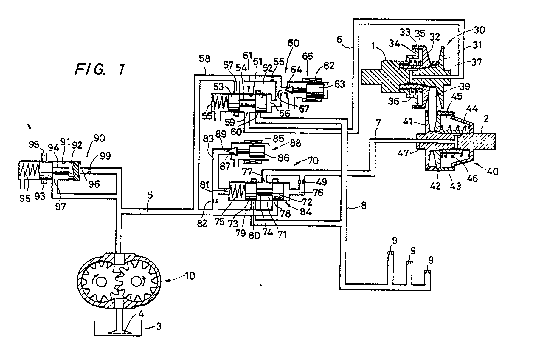
(57) Herein disclosed is a revolution speed ratio control system for a continuously variable
transmission. A driving pulley (30) is provided on an input shaft (1). a driven pulley
(40) is provided on an output shaft (2) disposed in parallel with the input shaft
(1). An endless belt (39) is wound on both the pulleys. Each of said pulleys comprises
a fixed member (31; 41) secured to the input or output shaft (1; 2) and having a conical
surface, and a movable member (32; 42) which has a conical surface facing that of
the fixed member and is provided so that the movable member is rotated together with
the input or output shaft (1; 2) and can be slid on the shaft in the axial direction
thereof. The endless belt (39) has both its oblique side surfaces frictionally engaged
with the conical surfaces of the fixed and movable members. An electronic control
circuit calculates the actual revolution speed ratio between the driving and driven
pulleys (30, 40) of the transmission, generates a first electric control signal corresponding
to the difference between the actual revolution speed ratio and an aimed revolution
speed ratio predetermined for both the pulleys (30, 40) in conjunction with the input
torque of the input shaft (1) and required torque for the output shaft (2), and generates
a second electric control signal made of the sum of both an electric signal corresponding
to the actual revolution speed ratio and an electric signal corresponding to the difference.
A hydraulic control circuit (50) includes a pressure oil source (10), a first cylinder
(33) which is provided on the input shaft (1) and supplied with working oil from the
pressure oil source to push the movable member (32) of the driving pulley (30) toward
the fixed member (31) thereof, a second cylinder (43) which is provided on the output
shaft (2) and supplied with working oil from the pressure oil source to push the movable
member (42) of the driven pulley (40) toward the fixed member (41) thereof, a first
control valve (61) which is disposed in an oil passage for connecting the pressure
oil source (10) and the first cylinder (33) to eachother and acts on the basis of
the first electric control signal to control the flow rate of the working oil supplied
to or drained from the first cylinder (33), and a second control valve (84) which
is disposed in an oil passage for connecting the pressure oil source (10) and the
second cylinder (43) to each other and acts on the basis of the second electric control
signal to control the pressure of the working oil supplied to the second cylinder
(43).
|
|
