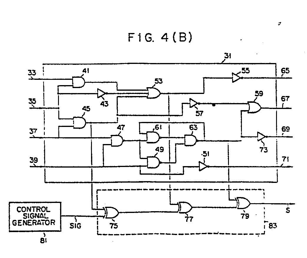
(57) @ A logic circuit according to this invention has a logic section (31). First input
terminals of first to third EX OR gates (75, 77, 79) are respectively connected to
output terminals of preselected logic elements (45, 53, 63) among the logic elements
which constitute the logic section (31). Output terminals of the first and second
EX OR gates (75, 77) are connected to second input terminals of the second and third
EX OR gates (77, 79). The functional test for this logic circuit is performed by inputting
test pattern signals to the logic section (31) and by comparing output signals of
the logic section (31) and an output signal (S) of the third EX OR gate (79) with
the expected values.
|
|
