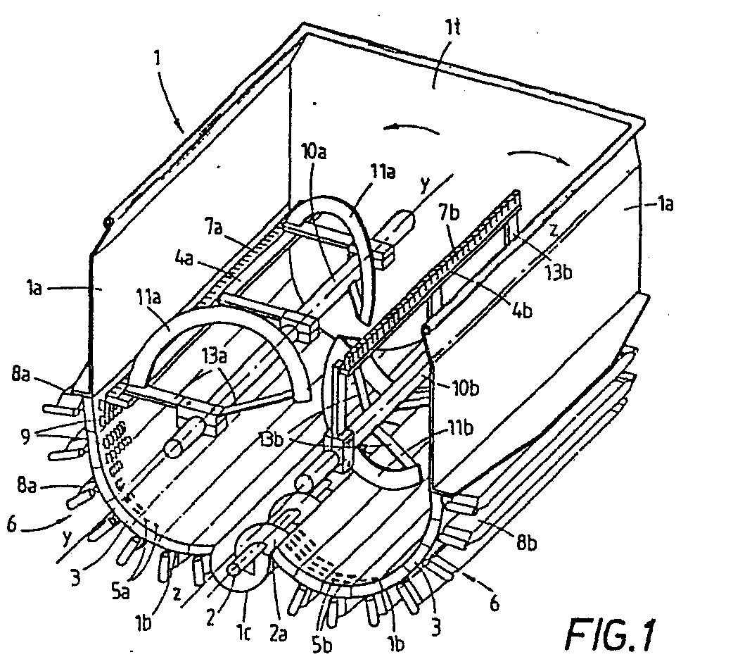
(57) A tank extractor (1) of a rectangular plan view, the bottom wall of which is substantially
shaped in the form of sectors (1b) of two partially interpenetrating cylinders, between
which a longitudinal channel (1c) is arranged, housing a screw (2, 2a) for the discharge
of the treated paste.
The bottom walls (1b) are formed as longitudinal segments or sub-sectors (3), in which
annular slits (5a, 5b) are arranged.
On the outside of each segment (3), a device (6a, 6b) is mounted comprising a longitudinal
bar (8a, 8b) supporting two pluralities of small blades (9) designed to penetrate,
at predetermined time intervals, through the slits (5a, 5b) so as to maintain these
latter disobstructed and to entrain the oil towards the outside.
The devices (6a, 6b) are driven by means, causing the small blades (9) to enter and
come out said slits radially and at predetermined time intervals.
In the tank (1) two twin kneading and mixing rotors are mounted comprising two longitudinal
shafts (10a, 10b) rotating in opposite directions, each of which carries lengths of
helicoidal blades (11a,11b) designed to operate in interlacing zones and which angularly
extend within a cylindrical sector of an angular amplitude not higher than 180°, as
well as longitudinal bars (4a, 4b) carrying comb-like devices (7a, 7b) with radial
teeth (28), made of elastomeric material, and which slide along the respective inner
surface of the walls (1 b). The teeth (28) are spaced apart from each other by slots
so that the small blades (5) can enter into the tank (1) and then into the slots of
the teeth (28) so as to clean also these latter.
|
|
