| (19) |
 |
|
(11) |
EP 0 293 501 A1 |
| (12) |
EUROPEAN PATENT APPLICATION |
| (43) |
Date of publication: |
|
07.12.1988 Bulletin 1988/49 |
| (22) |
Date of filing: 02.06.1987 |
|
|
| (84) |
Designated Contracting States: |
|
AT CH DE ES FR GB LI |
| (71) |
Applicant: Segoni, Aldo |
|
Florence (IT) |
|
| (72) |
Inventor: |
|
- Segoni, Aldo
Florence (IT)
|
| (74) |
Representative: Sassatelli, Franco T., Dr. |
|
c/o INIP
5, via Ruggi
40137 Bologna
40137 Bologna (IT) |
|
| |
|
| (54) |
Gradient-meter for motor-driven vehicles for checking the gradient of the road they
are running on |
(57) The invention object is an instrument- device in transparent envelope (1) to fit
on motor-driven vehicles either on the lower side of the wind-shield or above the
dashboard, and this device enables the driver during the trip to read the slop of
the vehicle in the running sense. This instrument (1) is characterized by a mobile
coloured plane which, after a proper self-control, slides in superposition on another
fixed plane having a different colour, so that, because the "chromatic blindness"
effect, a valid and easy reading of the value to check can be obtained.
|

|
[0001] Object of the present invention is an instrument with particular transparency visibility,
apt to check the slope of the vehicles both when ascending and when descending. The
above instrument, particularly suited for motor-vehicles, can be fitted either on
the dashboard or on the lower part of the windshield, so that to allow an easy visibility
to the driver without distracting his attention from the drive. It needs no electrical
or any other supply since its operation is autonomous.
[0002] The utility of this instrument is represented by the circumstance that, in general,
the drive is unable to value the gradient fairly enough, if any, of the way he is
running on, and this is due to different causes: impossibility of comparison with
a reference base plane, light winds that may alter the motor efficiency and so on.
The usefulness of the invention device consists, for instance in the charge-motor-vehicles,
in the possibility of timely changing the speed before perceiving the loss of the
motor revolutions on account of the greater effort in consequence of the unaperceived
slant. Also when descending, the fact of perceiving the exact gradient value can afford
to the driver a more exact evaluation for the speed to insert. Moreover, the circumstance
of having the slight slope of the road well evident, which cannot be easily evaluated
at a glance, when the driver is about to leave the stopped vehicle, enables him to
judge whether he should make the necessary arrangements against the risk of a self-move,
thus avoiding the heavy consequences which often occur in such cases.
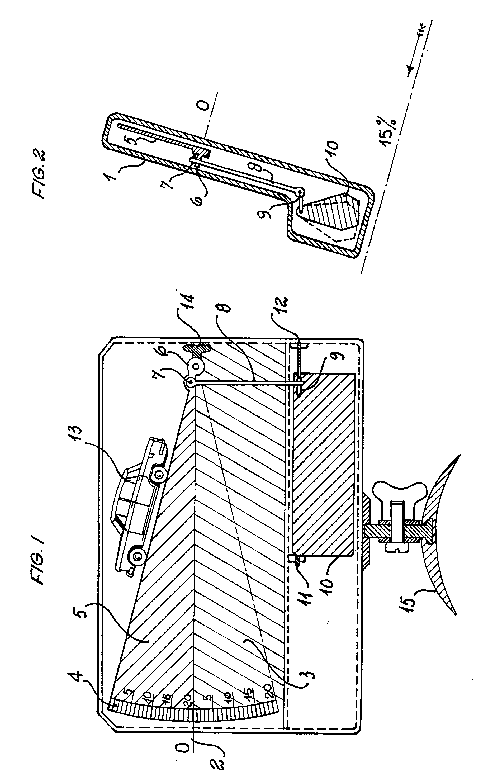
[0003] The invention device is illustrated in the drawings of table 1, where fig. 1 is
the perspective view of the device, whereas fig. 2 is the section view.
[0004] In a version, the instrument consists of a rectangular envelope in transparent material
1 in which a plane line 2 is marked on the ground representing the 0 (zero) as starting
reading base. The whole for instance red-coloured and transparent lower zone 3 has
the graphically marked graduation 4 on one side for reading the slant grades in percent.
Superposed on this bottom, another mobile also transparent -but differentrly coloured,
for instance green - is fitted with side fulcrum 6 and also with graphical graduation
4. This plane is connected by means of joint 7, articulation 8 and another joint
9, with a counterweight 10 which is swinging in both supports 11 and 12, and is fitted
with a counterpoise 14 to compensate its own weight which might negatively gravitate
against the operation. The instrument is fitted with a support 15 which is articulated
so as to regulate the setting-up (zero) in the device. On the upper line of plane
5, the drawing of a motor-driven vehicle 13 can be seen which will give the actual
view of how the vehicle is on that given slant. The device represented by the mobile
plane 5 and controlled by counterpoise 10 will be shifted upwards as soon as the route
gradient changes start ing from zero height and reaching the maximum heigh foreseen
of approx. 20%. Reading is facilitated by the circumstance that as soon as the mobile
plane 5 is shifted upwards, i.e. showing an ascent, the whole zone interested in the
reading will appear in green colour. This optical evidencing is due to the fact that
since the two planes 3 and 5 are of two different proper colours, when they are superposed,
owing to the "chromatic blidness", i.e. in the plane position of the vehicle, the
zone from 0 (zero) line downwards appears to be black, whereas the upper part is completely
white. The same occurs when the instrument indicates the descent: i.e. when the plane
5 sinks from line 0 (zero); in this case, the zone which is covered will appear in
red colour.
1) Gradient-meter for motor-driver vehicles for checking the gradient of the road
they are running on, characterized by the fact that a stiff transparent envelope (1)
is used with a straight line (2) marked on the ground and representing the reading
base. The whole lower zone (3) has a given colour and shows a side graduation (4)
for reading the slant degrees. On the said ground, a mobile plane (5) with different
colour has its fulcrum (6) near by sidewise, with a graduate scale (4) too. This
plane is connected, by means of an articulation (7), connecting rod (8) and a second
articulation (9), to a counterweight (1) which swings in two supports (11 and 12)
and is fitted with a second counterpoise (14) for compensating its own weight. The
instrument is fitted with an articulated support (15) for regulating the 0 (zero)
setting of the device. On the upper part of the plane (5), a motor-driven vehicle
(13) is represented which serves as the actual sight. The device represented by the
mobile plane (5) controlled by the counterpoised (10) movement is shifted upwards
when the road gradient is increasing and, in conformity, the whole zone interested
in reading appears with a given colour. This optical evidencing is increased by the
fact that the two flats are differently coloured, for instance red and green, and
through the "chromatic blindness", when superposed, they are causing, the zone below
the flat line appears black.