| (19) |
 |
|
(11) |
EP 0 202 457 B1 |
| (12) |
EUROPEAN PATENT SPECIFICATION |
| (45) |
Mention of the grant of the patent: |
|
07.02.1990 Bulletin 1990/06 |
| (22) |
Date of filing: 11.04.1986 |
|
| (51) |
International Patent Classification (IPC)5: B60T 8/28 |
|
| (54) |
Deceleration and pressure sensitive proportioning valve with high pressure damping
Verzögerungs- und druckabhängiges Bremsventil mit Dämpfung hoher Druckgradienten
Valve sensible à la pression et à la décélération avec un amortissement à haute pression
|
| (84) |
Designated Contracting States: |
|
DE FR GB IT |
| (30) |
Priority: |
24.05.1985 US 738116
|
| (43) |
Date of publication of application: |
|
26.11.1986 Bulletin 1986/48 |
| (73) |
Proprietor: AlliedSignal Inc. |
|
Morristown,
New Jersey 07962-2245 (US) |
|
| (72) |
Inventors: |
|
- Runkle, Dean Edward
P.O. Box 4001
South Bend
Indiana 46634 (US)
- Gaiser, Robert Frank
P.O. Box 4001
South Bend
Indiana 46634 (US)
|
| (74) |
Representative: Lejet, Christian et al |
|
BENDIX FRANCE Division Technique
Service Brevets Bendix Europe
126 rue de Stalingrad
93700 Drancy
93700 Drancy (FR) |
| (56) |
References cited: :
EP-A- 0 175 089
DE-A- 3 026 967
|
DE-A- 2 930 208
GB-A- 2 023 248
|
|
| |
|
|
|
|
| |
|
| Note: Within nine months from the publication of the mention of the grant of the European
patent, any person may give notice to the European Patent Office of opposition to
the European patent
granted. Notice of opposition shall be filed in a written reasoned statement. It shall
not be deemed to
have been filed until the opposition fee has been paid. (Art. 99(1) European Patent
Convention).
|
[0001] This invention relates to a deceleration and pressure sensitive proportioning valve
for the brake system of a vehicle, with a damping assembly provided in order to optimize
braking pressure.
[0002] EP-A-0175089, which is comprised in the state of the art according to Art.54(3)EPC,
discloses a proportioning valve assembly which may be disposed entirely within the
body of the master cylinder, and provides for deceleration and pressure sensitive
response in order to reduce the fluid pressure communicated to the rear wheels. By
reducing brake fluid pressure applied to the rear wheels in loaded and unloaded vehicle
situations, appropriate braking pressures are communicated to the rear wheels in accordance
with vehicle loading so that braking distance will be shortened and wheel lock-up
and subsequent skidding is eliminated or minimized. During sudden emergency situations,
a vehicle operator may suddenly apply full braking force to the brake pedal and cause
a very quick increase of pressure within the braking system. Within a manner of one
tenth of a second, the brake fluid can be increased from zero to approximately 70
bars (1000 psi). Such a sudden increase in brake fluid pressure resulting from a "spike"
apply to the brake pedal, can cause a proportioning valve assembly to operate improperly
so that the output pressure overshoots or exceeds the normal level where the proportioning
valve would begin to limit the output pressure to the rear wheels. The overshooting
or sudden increase in the brake pressure can then cause premature wheel lock-up and
potential skidding of the vehicle. It is desirable to provide a means for preventing
a sudden increase in brake fluid pressure from overshooting the normal break point
of the characteristic curve of the proportioning valve. The present invention provides
a solution for preventing pressure overshoot in output brake fluid pressure.
[0003] The present invention provides a proportioning valve assembly for a vehicle having
an inlet communicating with a fluid pressure source and an outlet communicating with
a brake assembly, a pressure responsive assembly cooperating with the inlet and the
outlet to vary fluid communication therebetween in response to pressurized fluid communicated
to the inlet, an inertia sensing mass responsive to deceleration of the vehicle and
cooperating with the pressure responsive assembly to assist in the variation of fluid
communicated between the inlet and the outlet, a fluid reservoir communicating with
the pressure responsive assembly, a channel providing the communication between the
pressure responsive assembly and the fluid reservoir, and valve means disposed in
said channel and engaged by said inertia sensing mass. (see EP-A-0 175 089).
[0004] According to this invention, this assembly comprises means for hydraulically damping
high pressure responsive assembly, said hydraulic damping means disposed within said
channel and hydraulically slowing the high pressure responsive operation of the pressure
responsive assembly so that said pressure responsive assembly is capable of varying
fluid pressure communicated to said outlet, the hydraulic damping of said high pressure
responsive operation effected by said pressure responsive assembly, hydraulic damping
means, channel, and valve means defining a restricted fluid communication path which
permits restricted fluid flow from the interior of the hydraulic damping means past
a portion of the pressure responsive assembly, through the hydraulic damping means,
to the channel means, past the valve means and into the reservoir.
[0005] The accompanying drawings show, for the purpose of exemplification without limiting
the invention of the claims thereto, certain practical embodiments illustrating the
principles of this invention wherein:
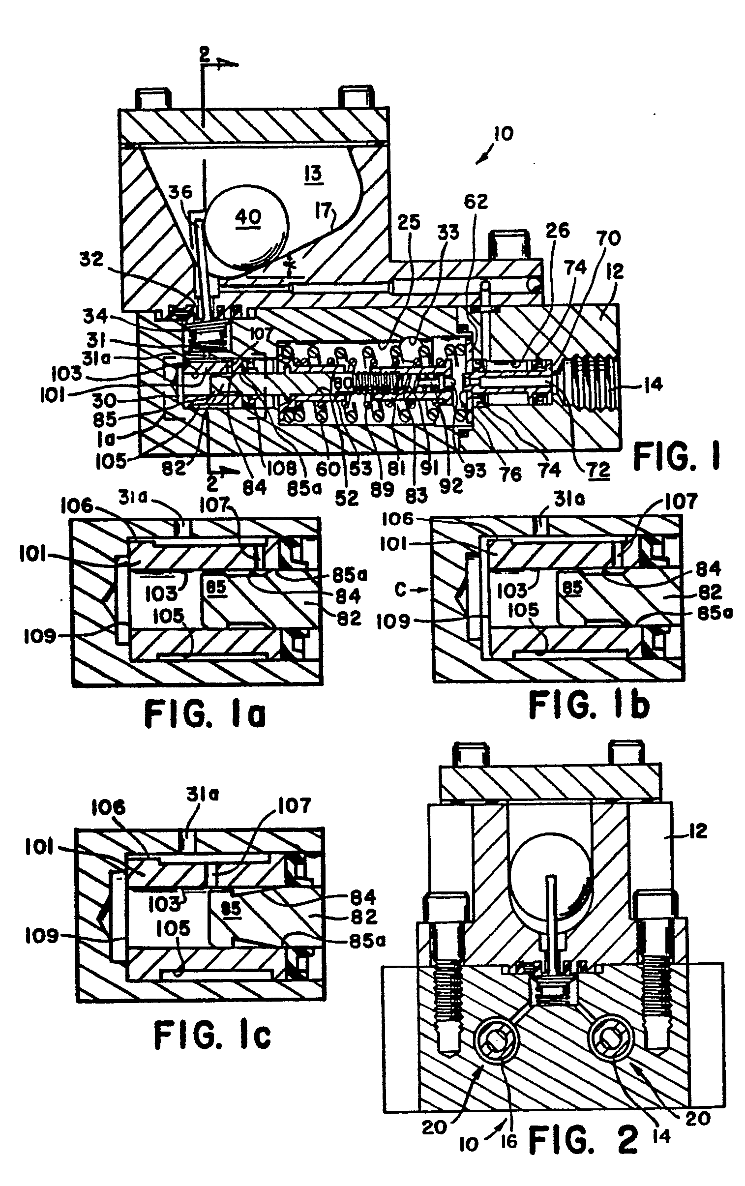
Figure 1 illustrates in section view a housing having two proportioning valves of
the present invention disposed within the body of the housing;
Figure 1a is an enlarged view illustrating the plunger and sleeve arrangement of the
present invention;
Figure 1b is an enlarged partial view illustrating the operation of the sleeve during
release of the brakes and cessation of braking;
Figure 1c illustrates an alternative embodiment of the sleeve and piston interface;
Figure 2 is a section view of the end of the housing of Figure 1;
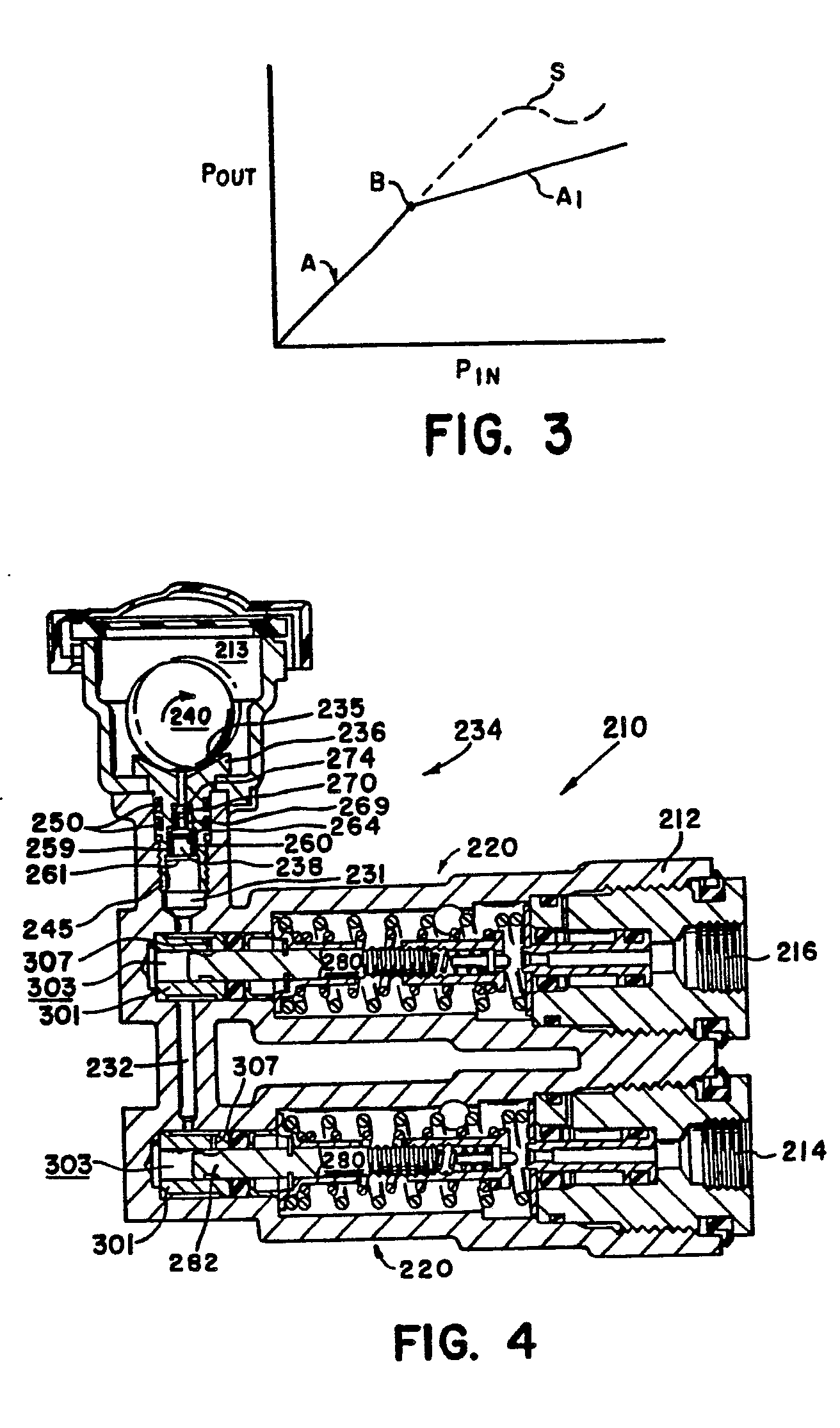
Figure 3 is a graph of Pout versus Pin for the proportioning valve of the present
invention; and
Figure 4 is a section view of two proportioning valves of the present invention disposed
within the body of a housing and illustrating the second valve means supporting thereon
an inertia sensitive object.
[0006] Figure 1-2 illustrate an embodiment of the proportioning valve assembly of the present
invention and which is designated generally by the reference numeral 10. The proportioning
valve assembly 10 may be contained within a housing 12 that is separate from the body
of the master cylinder (not shown). EP-A-0 175 089 discloses a deceleration and pressure
sensitve proportioning valve assembly which may be contained within the body of the
master cylinder, and said Application is incorporated by reference herein. Alternatively,
the present invention may be contained within a housing 12 which is separate from
the housing of the master cylinder and which has its own reservoir 13. The proportioning
valves 20 (see Figure 2) contained within the housing 12 are for a split braking circuit
having a fluid pressure outlet 14 communicating with a rear wheel cylinder and fluid
pressure outlet 16 communicating with the other rear wheel cylinder. Referring to
Figure 1 which illustrates in section view one of the proportioning valves 20, there
is illustrated a bore 25 which communicates with the master cylinder (not shown) by
means of passageway 33. Bore 25 communicates with a cavity 30 and channel 31 that
communicate with a reservoir 13, channel 31 including an opening 32 comprising the
opening of a second valve 34 which is illustrated as a tilt valve. Tilt or second
valve 34 may comprise any one of numerous valve constructions which would function
appropriately in the present invention, and one such alternative second valve embodiment
is illustrated in Figure 4, which will be explained hereinafter. An inertia sensitive
ball 40 is located separate from the path of fluid flow through proportioning valve
20 and within reservoir 13 on a ramp 17 which is disposed at an angle alpha oriented
upwardly towards the front of the vehicle. Second or tilt valve 34 includes arm 36
engaged by the inertia sensitive ball 40; inertia sensitive ball 40 holds the tilt
valve open until a certain predetermined attitude is attained by the vehicle during
deceleration or when deceleration displaces ball 40 up ramp 17. Bore 25 includes a
reduced diameter portion 26 having a differential piston 70 therein. Differential
piston 70 includes through opening 72 providing for communication of outlet 14 with
bore 25. Seals 74 are disposed about differential piston 70 which has valve seat 76
extending into bore 25 and with washer 62 disposed thereabout. A first spring 60 biases
the washer 62 and differential piston 70 to the right in Figure 1, with one end of
the spring 60 being received by guide 52. A second piston 80 comprises a longitudinal
member having one end threadably received in and supporting enclosure 81 and the other
end 82 received in cavity 30. Enclosure 81 defines a cavity 83 which contains poppet
92 therein biased by spring 91 towards valve seat 76. The second piston 80 is disposed
within a bore 53 of guide 52, so that the piston 80 may slide longitudinally relative
to guide 52. Spring 89 seats on guide 52 and biases the second piston to the right
in Figure 1. End 82 of second piston 80 is received within a bore 103 of sleeve 101,
and includes a reduced diameter portion 84. Sleeve 101 has a reduced exterior diameter
portion 105 containing therein an orifice 107. Seal 108 provides sealing engagement
between second piston end 82 and the walls of cavity 30.
[0007] The proportioning valves 20 contained with housing 12 operate in accordance with
the performance characteristics disclosed within EP-A-0 175 089. Pressurized brake
fluid received from inlet 33 passes through valve seat 76 and opening 72 to outlet
14 and to the wheel cylinder of a rear wheel brake. When the inlet pressure rises
to a level sufficient to displace differential piston 70 to the left in Figure 1,
valve seat 76 moves toward poppet end 93 to cause restriction of the brake fluid and
pressure communicated through opening 72 to the rear wheel brake. This establishes
a first brake point and if deceleration of the vehicle is sufficient to cause the
inertia sensitive ball to roll up ramp 17 (indicating an unloaded vehicle), then valve
34 closes and the closed channel 31 prevents movement to the left of second piston
80. Poppet valve 92 remains stationary so that end 93 restricts seat 76 and the output
pressure is metered accordingly. If deceleration of the vehicle is insufficient to
cause the ball 40 to roll up ramp 17 and close valve 34, then the increased inlet
pressure will cause the second piston 80 to move to the left against coil spring 89.
As second piston 80 moves to the left, poppet valve 92 moves therewith to retract
seat end 93 away from valve seat 76 and allow the increased input pressure to be communicated
through opening 72 to the rear brake wheel cylinder. This results in an increase in
the output pressure which increases the braking of the vehicle until the deceleration
causes the ball 40 to roll up ramp 17. Closure of the tilt valve 34 prevents any fluid
communication from cavity 30 and channel 31 to reservoir 13, and thereby prevents
second piston 80 from moving any furtherto the left. As piston 70 moves to the left
in accordance with the increase in input pressure, seat 76 again approaches the valve
seat end 93 and establishes a higher level brake point for a loaded vehicle. The restriction
of fluid flow through valve seat 76 by poppet end 93 results in a pressure curve for
a loaded vehicle.
[0008] The operational characteristics of the present invention are identical to that disclosed
in previous EP-A-0 175 089, and the present invention also includes an improved damping
means for accommodating sudden high pressure application or "spike" applies imposed
upon the braking system. The proportioning valve of the present invention includes
the same inherent bypass system provided for the previous described patent application,
wherein if one of the branches of the split circuit should fail, then there would
be less deceleration of the vehicle and the tilt valve of the operative branch would
stay open so that a higher brake fluid pressure received from the master cylinder
can be communicated to the associated brake cylinders. Thus, in case of failure, higher
braking pressures can be communicated to the associated brake wheel cylinder to effect
braking of the vehicle, and likewise for a system with a single proportioning valve.
[0009] The proportioning valve 20 of the present invention includes a sleeve 101 which provides
for damping when a "spike" apply is imposed upon the brake system. In the event of
an emergency situation, the vehicle driver may suddenly apply with full force the
brake pedal. This can cause the brake pressure to be increased from zero to approximately
one thousand pounds per square inch within a matter of approximately one tenth of
a second. Figure 3 illustrates the pressure output Pout of the braking system communicated
to the rear wheel brake cylinder in relationship to the pressure input Pin to the
braking system. Curve A represents an equal pressure output for an equal pressure
input during the initial phase of braking, and when a first brake point B is reached
in accordance with the normal braking conditions stated above, the curve should proceed
in accordance with curve A1. However, a "spike" or sudden high pressure application
of the braking system can cause the braking pressure to overshoot the brake point
B and follow the dotted line curve S. When the characteristic curve takes the form
of curve S and exceeds the desired pressure output curve A1, wheel lock-up will most
likely occur and steerable control of the vehicle will be lost. In proportioning valve
20, the sudden application of a high fluid pressure through inlet 33 to bore 25 could
cause the second piston 80 to move suddenly to the left, which correspondingly would
cause the poppet end 93 to move away from valve seat 76 and permit the full "spike"
applied fluid pressure to be communicated to the associated rear brake. In order to
prevent this, sleeve 101 is disposed about end 82 of second piston 80. The sudden
increase in brake pressure applied to bore 25 will move the piston 80 to the left
of Figure 1, but end 82 will compress the brake fluid within bore 103 of sleeve 101.
As illustrated in Figure 1a, the dimensions and tolerances of the sleeve 101 and end
182 are closely controlled so that there is a slight gap or clearance between bore
103 and end portion 85. The fluid flows from bore 103 around end 85 to reduce diameter
portion 84, through orifice 107 to exterior reduced diameter portion 105 and into
channel 31. By restricting the flow of fluid through sleeve 101 and orifice 107, there
is a damping effected for second piston 80. Because piston 80 cannot move quickly
to the left, the poppet end 93 remains adjacent the differential piston 76 and effectively
meters the outlet fluid pressure communicated through outlet 14. As a result, the
characteristic curves described above and in previous EP-A-0 175 089 are achieved
and the output curve S is avoided. It has been found that proportioning valve 20 of
the present invention improves the stopping distance of a vehicle, while minimizing
wheel lock-up. As a result, the driver may initiate a "spike" force application of
the brake pedal with the resulting creation of exceedingly high fluid pressures within
the proportioning valves 20, and obtain the predetermined output characteristics which
are desirable for both loaded and unloaded vehicle braking. Additionally, the present
invention continues to provide an inherent bypass feature in case one of the braking
circuits in a split circuit system would fail.
[0010] The reduced diameter portion 84 and orifice 107 utilise a lap-land approach for restricting
fluid flow. In other words, the movement of piston end 82 to the left will cause the
reduced diameter portion 84 to move out of alignment with the orifice 107. Fluid still
flows around the end 85 through reduced diameter portion 84 to the orifice 107, but
it is greatly slowed by the presence of the larger diameter area 85a being disposed
adjacent the orifice 107. In addition, the orifice 107 is offset from the opening
31a which further restricts fluid flow and pressure drop by providing multiple orifices
(107 and 31a) in series in accordance with the principles of fluid flow.
[0011] Figure 1b illustrates movement of sleeve 101 to the right in the direction of arrow
C when a brake application is being discontinued. When a brake application is discontinued,
the pressure within the bore 25 decreases rapidly and significantly to the extent
there may be a slight vacuum within bore 25. Piston 80 will return towards the right
if there is a sufficient replenishment of brake fluid within the chamber 30 and more
103 of sleeve 101. In order to effect this so that the return of piston 80 is not
delayed, sleeve 101 moves to the right under the effect of high pressure in chamber
30 and bore 103 than in bore 25, so that brake fluid may flow from channel 31 through
opening 31a to exterior reduced diameter portion 105, around sleeve end 108 and into
opening 109 in order to replenish the supply of brake fluid within bore 103. Thus,
the movement of sleeve 101 to the right alleviates any replenishment problem which
might greatly slow the return of second piston 80 to its proper at rest position.
[0012] Figures 1 and 2 illustrate the inertia sensitive ball 40 disposed on the U-shaped
ramp 17 which enables directional control of ball 40. The ramp 17 may contain one
or more lateral sides in order to limit, in one or more directions, the travel of
ball 40 during deceleration, and thereby provide deceleration and transverse acceleration
dependent control. The ramp 17 can be disposed in any direction relative to the longitudinal
axis of proportioning valve 20. Also, separate balls 40 and second valves 34 can be
provided for the proportioning valves 20 in order to provide deceleration and transverse
acceleration dependent controlled braking fluid pressures for the individual brakes.
[0013] Figure 1c illustrates an alternative embodiment of sleeve 101 wherein orifice 107
is aligned with end 85 of piston 82 and reduced diameter portion 84 is formed in the
shape of a bevelled opening. During a normal application of the brakes, there is little
difference in the functional characteristics exhibited by the sleeve-piston interfaces
of Figures 1a and 1c. During a "spike" application of the brakes, the alignment of
orifice 107 with piston end 85 results in an immediate restriction of fluid flowing
through orifice 107 as end 85 moves by the orifice, and the desired damping effect
is achieved. After an initial period of time and when fluid pressures begin to approximate
normal braking pressures, piston 82 has moved to the left in Figure 1c so that reduced
diameter portion 84 alignes with orifice 107 and fluid flow through orifice 107 is
less restricted. This results in piston 82 moving further to the left before the larger
diameter area 85a is disposed adjacent orifice 107 to restrict fluid flow through
the orifice and effect a knee-point or break-point in the characteristic output curve.
Thus, a higher break-point is achieved on the characteristic output curve, and, of
course, greater spacing achieved beween the break-points of the output curve.
[0014] Referring now to Figure 4, there is illustrated an alternative embodiment of the
second valve or tilt valve 34 of Figure 1. Similar components are identified by the
same numerals increased by 200. Like the previous embodiment, the inertia sensitive
ball is diposed in a location that is separate from the fluid flow path leading from
the master cylinder to the associated rear brake. Thus, the inertia sensitive ball
is not subject to fluid flow characteristics that occur within the fluid flow path
during braking. Second valve 234 comprises an annular ball 240 disposed within a cavity
or recess 235 of valve body 236. Valve body 236 including a stepped opening 238 which
communicates with channel 231. The proportioning valves 220 illustrated in Figure
4 are identical to the proportioning valves 20 illustrated in the previous Figures,
and are connected together by channel 232. Body 236 includes threads 245 which are
threadedly engaged with complementry threads of housing 212. 0-ring seals 250 are
disposed about body 236 in order to provide a seal between the housing 212 and body
236. Stepped opening 238 includes two valving members 260 and 270 in serial alignment
with respective valve seats 264 and 274. Spring 259 is positioned on clip 261 so as
to bias valve member 260 toward ball 240 and into engagement with valve 270, valve
270 being biased by spring 269 seated on valve member 260 so as to bias the valve
member 270 into engagement with ball 240.
[0015] It is important that the valve 234 operate properly in order to ensure that at the
appropriate predetermined times valve 234 closes and enables the appropriate characteristic
curve break points to be achieved. If the second valve in channel 31 should be damaged
or leak, the leakage of fluid pressure into reservoir 213 would change the operation
characteristics of proportioning valves 220 and correspondingly change the output
braking pressures communicated through outlets 214 and 216. Therefore, serially aligned
valve members 260 and 270 provide a redundant or dual valving arrangement to assure
that second valve 234 always operates properly. Valve member 260 is positioned slightly
closer to valve seat 264 than valve member 270 is positioned to valve seat 274. As
a result, when longitudinal or lateral deceleration of the vehicle causes the ball
240 to move from the recess 235, the valve member 260 will close seat 264 before the
valve member 270 closes seat 274. If there should be any leakage of fluid around valve
seat 264, the fluid pressure exerted against valve member 270 along with the spring
load of spring 269 and increased travel of ball 240, will cause valve member 270 to
seat against valve seat 274 and effect closure of second valve 234. Because second
valve 234 always operates properly, it is not possible for second pistons 280 to move
improperly to the left in Figure 4 and permit greater than desired output pressures
to be supplied through outlets 214 and 216 to the rear brakes. Thus, the desired output
pressures are assured by the serial valving arrangement of second valve 234.
[0016] Ball 240 depresses the valve members 260 and 270 downwadly against their respective
springs 259 and 269. Ball 240 is responsive not only to deceleration, but is responsive
to sharp cornering of the vehicle. The avoidance of excessive braking pressures should
be accomplished not only during logitudinal deceleration of the vehicle, but also
during lateral deceleration when the vehicle is rounding a curve. A wheel lock-up
occurring when the vehicle is rounding a curve, or cornering, can cause loss of control
of the vehicle. Thus, ball 240 is movable in any lateral direction relative to recess
235. The multi-directional movement capability of ball 240 renders second valve 234
responsive vectorily both to longitudinal deceleration and lateral deceleration of
the vehicle. Because of the law of linear progression, ball 240 will tend to proceed
or transversely accelerate along a straight line comprising a tangent to the curve
of the vehicle's path, so ball 240 moves from recess 235 and permits valve members
260 and 270 to operate. Thus, the present invention provides a deceleration and pressure
sensitive proportioning valve with a damping assembly which eliminates excessively
high braking pressures during a "spike" application of the brake pedal and also during
cornering of the vehicle by means of the appropriate operation of proportioning valves
220 in cooperation with second valve 234. Lateral sides or walls can be added as guides
that limit the movement of ball 240 in one or more directions so that the operation
of ball 240 is dependent upon the direction of deceleration or transverse acceleration.
As previously described, a separate ball 240 and second valve 234 can be provided
for each proportioning valve 220 in order to provide deceleration and transverse acceleration
dependent braking pressure for the individual wheels.
[0017] Although this invention has been described in connection with the illustrated embodiments,
it will be obvious to those skilled in the art that various changes may be made in
the form, structure, and arrangement of parts without departing from the inventions
as claimed.
1. A proportioning valve assembly (10, 210) for a vehicle having an inlet (33) communicating
with a fluid pressure source and an outlet (14; 214, 216) communicating with a brake
assembly, a pressure responsive assembly (20, 220) cooperating with the inlet (33)
and the outlet (14; 214, 216) to vary fluid communication therebetween in response
to pressurized fluid communicated to the inlet (33), an inertia sensing mass (40,
240) responsive to deceleration of the vehicle and cooperating with teh pressure responsive
assembly (20, 220) to assist in the variation of fluid communicated between the inlet
(33) and the outlet (14; 214, 216), a fluid reservoir (13, 213) communicating with
the pressure responsive assembly (20, 220), a channel (31, 231) providing the communication
between the pressure responsive assembly (20, 220) and the fluid reservoir (13,213),
and valve means (34, 234) disposed in said channel (31, 231) and engaged by said inertia
sensing mass (40, 240), characterized in that the assembly (10, 210) comprises means
(101, 301) for hydraulically damping high pressure responsive operation of said pressure
responsive assembly (20, 220), said hydraulic damping means (101, 301) disposed within
said channel (31, 231) and hydraulically slowing the high pressure responsive operation
of the pressure responsive assembly (20, 220) so that said pressure responsive assembly
(20, 220) is capable of varying fluid pressure communicated to said outlet (14; 214,
216), the hydraulic damping of said high pressure responsive operation effected by
said pressure responsive assembly (20, 220), hydraulic damping means (101, 301), channel
(31, 231), and valve means (34, 234) defining a restricted fluid communication path
which permits restricted fluid flow from the interior of the hydraulic damping means
(101, 301) past a portion of the pressure responsive assembly (20, 220), through the
hydraulic damping means (101, 301), to the channel means (31, 231), past the valve
means (34, 234) and into the reservoir (13, 213).
2. The proportioning valve assembly (10, 210) in accordance with claim 1, characterized
in that said pressure responsive assembly (20,220) includes a differential piston
(70) in a bore (25) of the valve assembly (10, 210), a second piston (80) located
for movement relative to the differential piston (70) and having an interior cavity
(83), and poppet valve means (92) disposed within the interior cavity (83).
3. The proportioning valve assembly (10, 210) in accordance with claim 2, characterized
in that the hydraulic damping means (101) comprises sleeve means (101) disposed within
said channel (31), and said second piston (80) extends into said channel (31) and
sleeve means (101).
4. The proportioning valve assembly (10, 210) in accordance with claim 3, characterized
in that said second piston (80) comprises a plunger end (82) which extends within
an interior bore (103) of said sleeve means (101), the plunger end (82) having a reduced
diameter portion (84), the sleeve means (101) having an exterior reduced diameter
portion (105) and an orifice (107) which communicates with the interior bore (103)
of the sleeve means (101 ).
5. The proportioning valve assembly (10, 210) in accordance with claim 4, characterized
in that said orifice (107) is in alignement with said reduced diameter portion (84)
of the plunger end (82) of said second piston (80) when the second piston (80) is
at rest, movement of the plunger end (82) relative to the sleeve means (101) causing
the reduced diameter portion (84) of the plunger end (82) to be non-aligned with said
orifice (107).
6. The proportioning valve assembly (10, 210) in accordance with claim 4, characterized
in that said orifice (107) is aligned with said plunger end (82) so as to communicate
directly with the interior bore (103) when the second piston (80) is at rest, movement
of the plunger end (82) relative to the sleeve means (101) causing the reduced diameter
portion (84) of the plunger end (82) to align with said orifice (107).
7. The proportioning valve assembly (10, 210) in accordance with claim 1, characterized
in that the assembly comprises guide means (52) disposed about said second piston
(80), the guide means (52) providing for guiding longitudinal movement of said second
piston (80) and providing a seat for resilient means (60).
8. The proportioning valve assembly (10, 210) in accordance with claim 1, characterized
in that said engagement of the valve means (34, 234) and inertia sensing mass (40,
240) provides for multi-directional movement of the mass (40, 240) relative to the
valve means (34, 234).
9. The proportioning valve assembly (10,210) in accordance with claim 1, characterized
in that the valve means (234) comprises serially aligned valve members (260, 270)
and valve seats (264, 274).
10. The proportioning valve assembly (10, 210) in accordance with claim 1, characterized
in that the inertia sensing mass (40) is disposed adjacent at least one guide means
(17) for controlling a direction of movement of said mass.
11. The proportioning valve assembly (10, 210) in accordance with claim 1, characterized
in that said valve means (234) supports said inertia sensing mass (240) for multi-directional
movement relative to the valve means (234), the valve means (234) having an area (235)
receiving the inertia sensing mass (240) thereat to engage valve closing means (270)
disposed within said valve means (234), - predetermined motion of said vehicle causing said inertia sensing mass (240) to move
away from said valve means (234) so that said valve closing means (270) closes the
valve means (234) to prevent fluid communication with the fluid reservoir (213) so
that the valve means (234) cooperates with the pressure responsive assembly (220)
in the variance of fluid communicated to said outlet (214, 216).
12. The proportioning valve assembly in accordance with claim 11, characterized in
that the valve closing means (270) comprises two valve closing members (260, 270)
each aligned with respective valve seats (264, 274) in said valve means (234), movement
of the inertia sensitive mass (240) enabling the valve members (260, 270) to close
the valve seats (264, 274).
13. The proportioning valve assembly in accordance with claim 12, characterized in
that said area (235) comprises a recess (235) and said inertia sensing mass (240)
comprises a generally circular ball (240) which may move multi-directionally from
said recess (235) and allow said valve closing members to close said valve seats (264,
274).
14. The proportioning valve assembly in accordance with claim 13, characterized in
that the assembly comprises resilient means (259, 269) biasing said valve closing
members toward closure of said valve seats (264, 274), the valve closing members (260,
270) being aligned serially with a first valve member (270) engaging said ball (240).
15. The proportioning valve assembly in accordance with claim 13, characterized in
that the assembly comprises a shoulder (261) within said valve means (234) which provides
support for first resilient means (259) which biases a second one (260) of said valve
closing members (260, 270) toward the respective valve seat (264), and the second
valve closing member providing a shoulder (260) for second resilient means (269) which
biases said first valve closing member (270) toward closure of the respective valve
seat (274).
16. The proportioning valve assembly in accordance with claim 11, characterized in
that the assembly comprises directional guide means (17) for preventing movement of
said inertia sensing mass (40) in at least one direction.
1. Dosierventileinheit (10, 210) für ein Fahrzeug mit einem Einlaß (33), der mit einer
Strömungsdruckquelle in Verbindung steht, und einem Auslaß (14; 214, 216), der mit
einer Bremseinheit in Verbindung steht, einer druckabhängigen Einheit (20, 220), die
mit dem Einlaß (339) und dem Auslaß (14; 214, 216) zusammenwirkt, um die Strömungsmittelverbindung
dazwischen in Abhängigkeit von unter Druck stehendem Strömungsmittel, das dem Einlaß
(33) zugeführt wird, zur verändern, einer Trägheitserfassungsmasse (40, 240), die
auf eine Verzögerung des Fahrzeuges anspricht und mit der druckabhängigen Einheit
(20, 220) zusammenwirkt, um zur Veränderung der Strömungsmittelverbindung zwischen
dem Einlaß (33) und dem Auslaß (14; 214, 216) beizutragen, einem Strömungsmittelspeicher
(13, 213), der mit der druckabhängigen Eineheit (20, 220) in Verbindung steht, einem
die Verbindung zwischen der druckabhängigen Einheit (20, 220) und dem Strömungsmittelspeicher
(13, 213) bildenden Kanal (31, 231) und einer im Kanal (31, 231) angeordneten Ventileinrichtung
(34,234), die mit der Trägheitserfassungsmasse (40, 240) in Eingriff steht, dadurch
gekennzeichnet, daß die Einheit (20, 210) eine Einrichtung (101, 301) zum hydraulischen
Dämpfen des hochdruckabhängigen Betriebes der druckabhängigen Einheit (20, 220) aufweist,
die im Kanal (31, 231) angeordnet ist und dem hochdruckabhängigen Betrieb der druckabhängigen
Einheit (20, 220) hydraulisch derart verlangsamt, daß die druckabhängige Einheit (20,
220) in der Lage ist, dem dem Auslaß (14; 214, 216) zugeführten Strömungsmitteldruck
zu verändern, wobei die von der druckabhängigen Einheit (20, 220) durchgeführte hydraulische
Dämpfung des hochdruckabhängigen Betriebes, die hydraulische Dämpfungseinrichtung
(101, 301), der Kanal (31,231) und die Ventileinrichtung (34, 234) eine gedrosselte
Strömungsmittelverbindungsbahn vorsehen, die einen gedrosselten Strömungsmittelfluß
vom Inneren der hydraulischen Dämpfungseinrichtung (101, 301) an einem Abschnitt der
druckabhängigen Einheit (20, 220) vorbei durch die hydraulische Dämpfungseinrichtung
(101, 301) zur Kanaleinrichtung (31, 231) an der Ventileinrichtung (34, 234) vorbei
und in den Speicher (13, 213) ermöglicht.
2. Dosierventileinheit (10, 220) nach Anspruch 1, dadurch gekennzeichnet, daß die
druckabhängige Einheit (20, 220) in einer Bohrung (25) der Ventileinheit (10, 210)
einen Differenzkolben (70), einen zweiten Kolben (80), der relativ zum Differenzkolben
(70) bewegbar ist und einen inneren Hohlraum (83) aufweist, und eine Tellerventileinrichtung
(92) umfaßt, die im inneren Hohlraum (83) angeordnet ist.
3. Dosierventileinheit (10, 210) nach Anspruch 2, dadurch gekennzeichnet, daß die
hydraulische Dämpfungseinrichtung (101) eine im Kanal (31) angeordnete Hülseneinrichtung
(101) aufweist und daß sich der zweite Kolben (80) in den Kanal (31) und die Hülseneinrichtung
(101) erstreckt.
4. Dosierventileinheit (10, 210) nach Anspruch 3, dadurch gekennzeichnet, daß der
zweite Kolben (80) ein Kolbenende (82) umfaßt, das sich in eine Innenbohrung (103)
der Hülseneinrichtung (101) erstreckt und einen Abschnitt (84) mit reduziertem Durchmesser
aufweist, und daß die Hülseneinrichtung (101) einen äußeren Abschnitt (105) mit reduziertem
Durchmesser sowie eine Öffnung (107) besitzt, die mit der Innenbohrung (103) der Hülseneinrichtung
(101) in Verbindung steht.
5. Dosierventileinheit (10, 210) nach Anspruch 4, dadurch gekennzeichnet, daß die
Öffnung (101) zu dem Abschnitt (84) mit reduziertem Durchmesser des Kolbenendes (82)
des zweiten Kolbens (80) ausgerichtet ist, wenn sich der zweite Kolben (80) in Ruhe
befindet, und daß eine Bewegung des Kolbenendes (82) relativ zur Hülseneinrichtung
(101) bewirkt, daß der Abschnitt (84) mit reduziertem Durchmesser der Kolbenendes
(82) mit der Öffnung (107) außer flucht gebracht wird.
6. Dosierventileinheit (10, 210) nach Anspruch 4, dadurch gekennzeichnet, daß die
Öffnung (107) zum Kolbenende (82) ausgerichtet ist, so daß eine direkte Verbindung
mit der Innenbohrung (103) hergestellt ist, wenn sich der zweite Kolben (80) in Ruhe
befindet, und daß eine Bewegung des Kolbenendes (82) relativ zur Hülseneinrichtung
(101) bewirkt, daß der Abschnitt (84) mit reduziertem Durchmesser des Kolbenendes
(82) zur Öffnung (107) ausgerichtet wird.
7. Dosierventileinheit (10, 210) nach Anspruch 1, dadurch gekennzeichnet, daß die
Einheit eine um den zweiten Kolben (80) angeordnete Fühgrungseinrichtung (52) umfaßt,
die die Längsbewegung des zweiten Kolbens (80) führt und einen Sitz für eine elastische
Einrichtung (60) bildet.
8. Dosierventileinheit (10, 210) nach Anspruch 1, dadurch gekennzeichnet, daß der
Eingriff zwischen der Ventileinrichtung (34, 234) und der Trägheitserfassungsmasse
(40, 240) für eine Bewegung der Masse (40, 240) relativ zur Ventileinrichtung (34,234)
in mehrere Richtungen sorgt.
9. Dosierventileinheit (10, 210) nach Anspruch 1, dadurch gekennzeichnet, daß die
Ventileinrichtung (234) in Reihe ausgerichtete Ventilelemente (260, 270) und Ventilsitze
(264, 274) umfaßt.
10. Dosierventileinheit (10, 210) nach Anspruch 1, dadurch gekennzeichnet, daß die
Trägheitserfassungsmasse (40) benachbart zumindest einer Führungseinrichtung (17)
angeordnet ist, um eine Bewegungsrichtung der Masse zu steuern.
11. Dosierventileinheit (10, 210) nach Anspruch 1, dadurch gekennzeichnet, daß die
Ventileinrichtung (234) die Trägheitserfassungsmasse (240) für eine Bewegung relativ
zur Ventileinrichtung (234) in mehrere Richtungen lagert, daß die Ventileinrichtung
(234) einen Bereich (235) aufweist, der auf sich die Trägheitserfassungsmasse (240)
aufnimmt, um mit einer in der Ventileinrichtung (234) angeordneten Ventilschließeinrichtung
(270) in Eingriff zu treten, und daß eine vorgegebene Bewegung des Fahrzeuges bewirkt,
daß sich die Trägheitserfassungsmasse (240) von der Ventileinrichtung (234) wegbewegt,
so daß die Ventilschließeinrichtung (270) die Ventileinrichtung (234) schließt, um
eine Strömungsmittelverbindung mit dem Strömungsmittelspeicher (213) zu verhindern,
so daß die Ventileinrichtung (234) bei der Veränderung des dem Auslaß (214, 216) zugeführten
Strömungsmittels mit der druckabhängigen Einheit (220) zusammenwirkt.
12. Dosierventileinheit nach Anspruch 11; dadurch gekennzeichnet, daß die Ventilschließeinrichtung
(270) zwei Ventilschließelemente (260, 270) aufweist, die jeweils mit entsprechenden
Ventilsitzen (264, 274) in der Ventileinrichtung (234) ausgerichtet sind, und daß
eine Bewegung der Trägheitserfassungsmasse (240) eine Schließen der Ventilsitze (264,
274) durch die Ventilelemente bewirkt.
13. Dosierventileinheit nach Anspruch 12, dadurch gekennzeichnet, daß der Bereich
(235) eine Ausnehmung (235) und die Trägheitserfassungsmasse (240) eine allgemein
kreisförmige Kugel (240) umfaßt, die sich von der Ausnehmung (235) in mehrere Richtungen
bewegen und den Ventilschließelementen ermöglichen kann, die Ventilsitze (264, 274)
zu schließen.
14. Dosierventileinheit nach Anspruch 13, dadurch gekennzeichnet, daß die Einheit
elastische Einrichtungen (259, 269) aufwiest, die die Ventilsitze (264, 274) vorspannen,
und daß die Ventilschließelemente (260, 270) in Reihe zu einem ersten Ventilelement
(270) ausgerichtet sind, das mit der Kugel (240) in Eingriff steht.
15. Dosierventileinheit nach Anspruch 13, dadurch gekennzeichnet, daß sie eine Schulter
(261) innerhalb der Ventileinrichtung (234) aufweist, die eine Lager für erste elastische
Einrichtungen (259) bildet, welche ein zweites (260) der Ventilschließelemente (260,
270) in Richtung auf den entsprechenden Ventilsitz (264) vorspannen, und daß das zweite
Ventilschließelement eine Schulter (260) für zweite elastische Einrichtungen (269)
bildet, die das erste Ventilschließelement (270) in Richtung auf ein Schließen des
entsprechenden Ventilsitzes (274) vorspannen.
16. Dosierventileinheit nach Anspruch 11, dadurch gekennzeichnet, daß sie eine Richtungsführungseinrichtung
(17) aufweist, die eine Bewegung der Trägheitserfassungsmase (40) in mindestens einer
Richtung verhindert.
1. Ensemble de valve de répartition (10, 210) pour un véhicule comprenant un entrée
(-33) communiquant avec une source de pression de fluide et une sortie (14; 214, 216)
communiquant avec un ensemble de frein, un ensemble sensible à la pression (20, 220)
agissant conjointement avec l'entrée (33) et la sortie (14, 214, 216) pour faire varier
la transmission du fluide entre led deux en réponse au fluide sous pression transmis
à l'entrée (33), une masse d'inertie (40, 240) sensible à la décélération du véhicule
et agissant conjointment avec l'ensemble sensible à la pression (20, 220) pour assister
dans la variations du fluide transmis entre l'entrée (33) et la sortie (14; 214, 216),
un réservoir de fluide (13,213) communiquant avec l'ensemble sensible à la pression
(20,220), un canal (31,231) établissant la communication entre l'ensemble sensible
à la pression (20, 220) et le réservoir de fluide (13, 213), et une valve (34, 234)
disposée dans la canal (31, 231) et au contact de la masse d'inertie (40,240), caractérisé
en ce que l'ensemble (10, 210) comprend un moyen (101, 301) pour amortir hydrauliquement
la haute pression sensible au fonctionnement de l'ensemble sensible à la pression
(20, 220) le dit moyen d'amortissement hydraulique (101, 301) éant disposé dans le
canal (31,231) et ralentissant hydrauliquement la fonctionnement de l'ensem- bvle
sensible à la pression (20, 220) de telle sorte que ce dernier soit capable de faire
varier la pression du fluide transmis à la sorte (14; 214, 216) l'amortissement hydraulique
de la dite haute pression effectué par l'ensemble sensible à la pression (20, 220)
le moyenm d'amortissement hydraulique (101, 301), le canal (31, 231) et la valve (34,
234) définissant un chemin de fluide limité qui permet au fluide limité de passer
de l'intérieur du moyen d'amortissement hydraulique (101, 301) au-delà d'une partie
de l'ensemble sensible à la pression (20, 220), à travers le moyen d'amortissement
hydraulique (101, 301) au canal (31, 231) au-delà de la valve (34, 234) et dans le
réservoir (13, 213).
2. Ensemble de valve de répartition (10, 210) selon la revendication 1, caractérisé
en ce que l'ensemble sensible à la pression 20, 220), inclut un piston différentiel
(70) disposé dans un alésage (25) de l'ensemble de valve (10, 210), un second piston
(80) placé pour se déplacer par rapport au piston différentiel (70) et pourvu d'une
cavité intérieur (83), et un clapet (92) disposé à l'intérieur de la cavité (83).
3. Valve de répartition (10,210) selon la revendication 2, caractérisé en ce que le
moyen d'amortissement hydraulique (101) comprend un manchon (101) disposé dans le
canal (31) et que le second piston (80) s'étend dans le canal (31) et le manchon (101).
4. Valve de répartition (10,210) selon la revendication 3, caractérisé en ce que le
second piston (80) compend une extrémité (82) qui s'étend dans un alésage intérieur
(103) du manchon (101), l'extrémité (82) ayant une partie de diamètre plus faible
(84), le manchon (101) ayant une partie de diamètre extérieur plus faible (105) et
un orifice (107) qui communique avec l'alésage intérieur (103) du manchon (101).
5. Valve de répartition (10,210) selon la revendication 4, caractérisé en ce que l'orifice
(107) est un alignement avec la partie de diamètre plus faible (84) de l'extrémité
(82) par rapport au piston (80) quand ce dernier est au repos, le mouvement de l'extrémité
(82) par rapport au manchon (101) provoquant le non alignement de la partie de diamètre
plus faible (84) de l'extrémité (82) du piston avec l'orifice (107).
6. Valve de répartition (10,210) selon la revendication 4, caractérisé en ce que l'orifice
(107) est aligné avec l'extrémité (82) de façon à communiquer directement avec l'alésage
intérieur (103) lorsque le second piston (80) est au repos, le mouvement de l'extrémité
(82) par rapport au monchon (101) provoquant l'alignement de la partie de diamètre
plus faible (84) de l'extrémité (82) avec l'orifice'(107).
7. Ensemble de valve de répartition (10, 210) selon la revendication 1, charactérisé
en ce que qu'il comprend un moyen de guidage (52) disposé autour du piston (80), le
moyen de guidage (52) assurant le guidage du mouvement longitudinal du second piston
(80) et servant de siège pour un moyen élastique (60).
8. Ensemble de valve de répartition (10, 210) selon la revendication 1, caractérisé
en ce que le contact entre la valve (34, 234) assure le mouvement multi directionnel
de la mase (40, 240) par rapport à la valve (34, 234).
9. Ensemble de valve de répartition (10, 210) selon la revendication 1, caractérisé
en ce que la valve (234) comprend des éléments de valve (260, 270) alignés en série
et des sièges (264, 274).
10. Ensemble de valve de répartition (10, 210) selon la revendication 1, caractérisé
en ce que la masse d'inertie (40) est disposée adjacente à au mois un moyen de guidage
(17) commandant une direction de mouvement de la dite masse.
11. Ensemble de valve de répartition (10, 210) selon la revendication 1, caractérisé
en ce que la valve (234) supporte la masse d'inertie (240) pour un mouvement multi-directionnel
par rapport à la valve (234), cette dernière étant pourvue d'une partie (235) recevant
la masse (240) au contact du moyen de fermeture de la valve (270) disposé dans la
valve (234), le mouvement prédéterminé du véhicule provoquant l'éloignement de la
valve (234) de la masse (240), afin que le moyen de fermeture de la valve (270) ferme
cette dernière pour interdire la transmission du fluide au réservoir de fluide (213)
de telle sorte que la valve (234) agisse conjointement avec l'ensemble sensible à
la pression (220) à la variation du fluide transmis à la sortie (214, 216).
12. Ensemble de valve de répartition selon la revendication 11, caractérisé en ce
que le moyen de fermeture (270) comrend deux éléments de fermeture (260, 270) alignés
chacun avec leurs sièges respectifs (264, 274) dans la valve (234), le mouvement de
la masse (240) rendant possible aux éléments (260, 270) de fermer les sièges (264,
274).
13. Ensemble de valve de répartition selon la revendication 12, caractérisé en ce
que la partie 235 comrend un évidement et que la masse (240) est constituée par une
bille qui peut se déplacer multidirectionnellement sur l'évidement et permettre aux
éléments de fermeture de la valve de fermer les sièges (264, 274).
14. Ensemble de valve de répartition selon la revendication 13, caractérisé en ce
qu'il comprend des moyens élastiques (259, 269), déviant les éléments de fermeture
vers les sièges (264, 274), les éléments de fermeture (260, 270) étant alignés en
série avec un premier élément (270) au contact de la bille (240).
15. Ensemble de valve de répartition selon la revendication 13, caractérisé en ce
qu'il comprend un épaulement (261) à l'intérieur de la valve (234) supportant le premier
moyen élastique (259) qui dévie le second (260) des éléments de fermeture (260, 270)
vers le siège correspondant (264), et le second élément de fermeture de la valve constituant
un épaulement (260) pour le moyen élastique (269) qui dévie le premier élément de
fermeture de la valve (270) ves la fermeture du siège de valve correspondant (274).
16. Ensemble de valve de répartition selon la revendication 11, caractérisé en ce
qu'il comprend un moyen de guidage directionnel (17) interdisant le mouvement de la
masse (40) dans au moins une direction.