| (19) |
 |
|
(11) |
EP 0 251 519 B1 |
| (12) |
EUROPEAN PATENT SPECIFICATION |
| (45) |
Mention of the grant of the patent: |
|
07.02.1990 Bulletin 1990/06 |
| (22) |
Date of filing: 08.06.1987 |
|
|
| (54) |
Solenoid operated fluid flow control valves
Magnetisch betätigte Fluidströmungs-Steuerventile
Valves de commande actionnées magnétiquement pour l'écoulement de fluide
|
| (84) |
Designated Contracting States: |
|
DE FR GB IT |
| (30) |
Priority: |
14.06.1986 GB 8614516
16.09.1986 GB 8622278
|
| (43) |
Date of publication of application: |
|
07.01.1988 Bulletin 1988/01 |
| (73) |
Proprietor: LUCAS INDUSTRIES public limited company |
|
Birmingham, B19 2XF
West Midlands (GB) |
|
| (72) |
Inventor: |
|
- Bayliss, John Patrick
Redditch
Worchestershire B97 4NF (GB)
|
| (74) |
Representative: Spall, Christopher John et al |
|
BARKER, BRETTELL & DUNCAN
138 Hagley Road
Edgbaston
Birmingham B16 9PW
Edgbaston
Birmingham B16 9PW (GB) |
| (56) |
References cited: :
EP-A- 0 149 239
EP-A- 0 202 845
DE-A- 2 751 150
|
EP-A- 0 171 901
DE-A- 2 710 067
DE-A- 3 542 131
|
|
| |
|
|
|
|
| |
|
| Note: Within nine months from the publication of the mention of the grant of the European
patent, any person may give notice to the European Patent Office of opposition to
the European patent
granted. Notice of opposition shall be filed in a written reasoned statement. It shall
not be deemed to
have been filed until the opposition fee has been paid. (Art. 99(1) European Patent
Convention).
|
[0001] This invention relates to improvements in solenoid-operated fluid-flow control valves.
Particularly the invention is concerned with solenoid-operated flow control valves
for use in hydraulic anti-skid braking systems for vehicles.
[0002] Known solenoid-operated flow control valves for use in hydraulic anti-skid braking
systems usually incorporate two solenoid coils, each of which controls a respective
valve, and the coils are energised sequentially in response to energising currents
dependent upon skid signals from a wheel speed sensor in order to control the behaviour
of a respective braked wheel. For example, one of the valves may control either directly
or indirectly the supply of brake-applying fluid to brake-applying means, and the
second valve may act as a brake- pressure release device operative to reduce the pressure
of fluid applied to the brake when a skid signal is operative.
[0003] We are also aware of U.S. Patent No. 4 619 289 of Nippondenso Co. Ltd. of Japan,
which discloses an anti-skid system in which a single solenoid coil is arranged to
control two valves sequentially by varying the current to the solenoid from a low
level at which only one valve operates to a high level at which both valves are operated.
[0004] We are also aware of U.S. Patent No. 4 655 255 of Rode which discloses an electromagnetically
controlled multiway valve in which energisation of the solenoid at a first level closes
a first valve against the action of a weak spring while energisation at a higher level
moves an armature against the action of a second stronger spring to open a second
valve.
[0005] According to our invention a solenoid-operated fluid-flow control valve comprises
a single solenoid coil, the energisation of which is adapted to control first and
second armatures associated with first and second respective valve means controlling
flow between opposite first and second ends of the solenoid coil, the solenoid coil
having a central core with a central core passage, the first valve means being provided
at one end of the core passage and comprising a valve member on the first armature
which co-operates with a valve seating on the core, the second valve means being provided
at, or adjacent, to the opposite end of the core passage and means are incorporated
defining a variable restrictor operable in response to movement of the first valve
member relative to the valve seating and defining a fixed fluid restrictor which acts
in series with the variable restrictor.
[0006] Preferably each valve means comprises a valve member for co-operation with a seating
at or adjacent to a respective end of the solenoid coil, and a spring for urging the
valve member in one direction with respect to the seating, the relative strengths
of the springs being chosen such that, upon energisation of the solenoid coil, one
valve member is moved relatively towards its respective seating before the other valve
member is moved away from its respective seating.
[0007] In such a construction. the spring which acts to urge the first valve member away
from the seating is weaker than the spring of the second valve means. Specifically
the relative strengths of the two springs are chosen to ensure that upon energisation
of the single solenoid coil at a single energy level the strength of the flux field
which increases upon the -co-operation of the first valve member with the seating
can overcome the loading in the spring of the second valve means.
[0008] Alternatively the force acting on the armatures can be varied by varying the spring
loading acting on the armatures, varying the flux density from one end of the solenoid
to the other, or by varying the pole area of the ends of the solenoid, or by any combination
of these three means.
[0009] When the solenoid-operated valve is incorporated in an hydraulic anti-skid braking
system for vehicles, the first valve means controls the supply of fluid to brake-applying
means, and the second valve controls a flow path from the brake-applying means to
a reservoir or dump chamber for fluid, energisation of the solenoid coil in response
to a skid signal causing the first valve member to engage with the seating to isolate
the supply of fluid from the brake-applying means, followed by movement of the valve
member of the second valve means away from the respective seating to release pressure
from the brake-applying means.
[0010] In one construction the energy from a brake-application sustaining source, suitably
an hydraulic accumulator, is applied to the brake-applying means through a fixed restrictor
and a variable restrictor in series with it, the variable restrictor being defined
by co-operation of the valve member of the first valve with a its seating on the central
core.
[0011] This ensures that the second valve will isolate the flow path to the reservoir before
the double-acting valve can re-apply the pressure from the sustaining source to the
brake-applying means.
[0012] The fixed restrictor may comprise an orifice in a flexible diaphragm which otherwise
provides an imperforate seal between the accumulator and the brake-applying means.
[0013] In another construction energy from a brake-applying re-application means, suitably
an hydraulic pump, is applied to the brake-applying means through a fixed restrictor
and a variable restrictor in series with it, the variable restrictor being defined
by the co-operation of a valve member carried by a diaphragm with a seating spaced
from the seating at the end of the core and with which the first valve member of the
first valve means is engageable, and the fixed restrictor is provided in the diaphragm
itself.
[0014] Two embodiments of our invention are illustrated in the accompanying drawings in
which:-
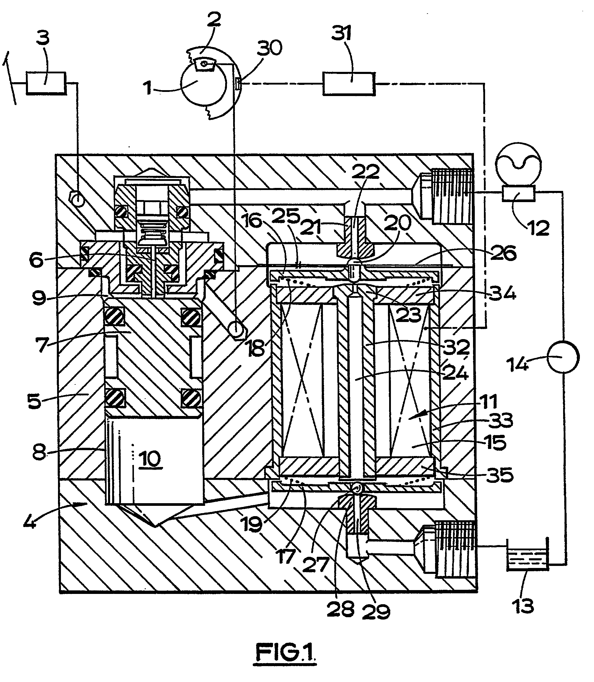
Figure 1 is a layout of an hydraulic anti-skid braking system for a vehicle; and
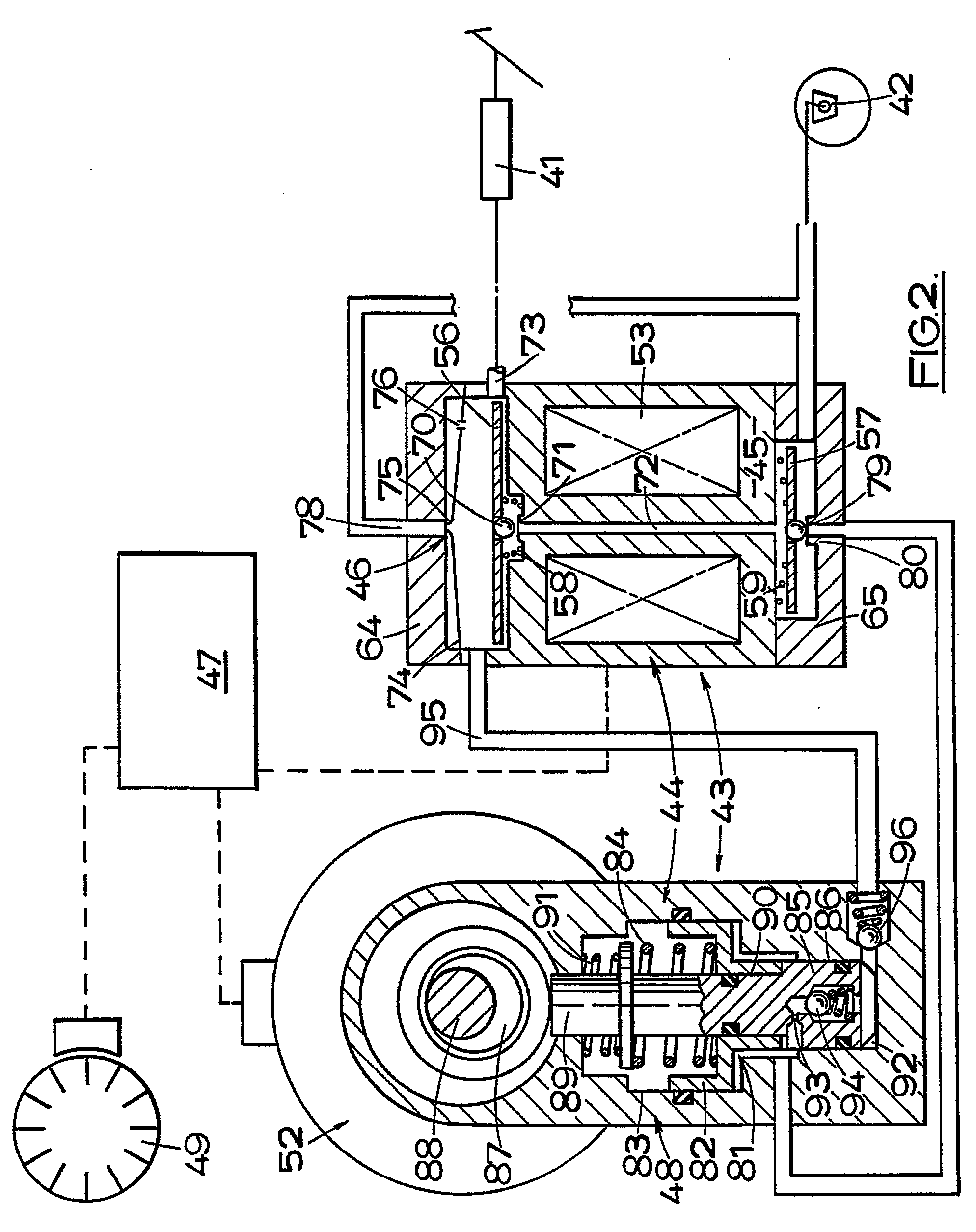
Figure 2 is a layout of another hydraulic anti-skid braking system.
[0015] In the braking system illustrated in Figure 1 of the drawings a brake 1 on a wheel
2 of a vehicle is adapted to be applied by a pedal-operated master cylinder 3, and
the supply of fluid from the master cylinder 3 to the brake 1 is modulated in accordance
with the behaviour of the wheel 2 by a modulator assembly 4.
[0016] The modulator assembly 4 comprises a housing 5 incorporating a cut-off valve 6 which
is operated by an expander piston -7.-working in a bore 8. An expansion chamber 9
is defined in the bore 8 between the piston 7 and the valve 6, and the position of
the piston 7 in the bore 8 is determined by the volume of fluid trapped in a support
chamber 10 at the opposite end of the piston 7.
[0017] A solenoid-operated valve 11 incorporated in the housing 5 controls the supply of
fluid to the chamber 10 from an hydraulic accumulator 12 and the release of fluid
from the chamber 10 to reservoir 13 from which the accumulator 12 is charged by a
pump 14 which is either driven by an electric motor, or from the prime mover of the
vehicle.
[0018] The solenoid-operated valve 11 comprises a single solenoid coil 15 for controlling
operation of first and second armatures 16 and 17 at opposite ends of the coil 15
and which are biassed away from the coil 15 by first and second respective compression
springs 18 and 19 of which the spring 18 is weaker than the spring 19. The armatures
16 and 17 may be equal in area. The coil 15 has a central core 32 and an external
cylinder housing 33 which are interconnected by annular end closures 34 and 35 of
non-magnetic material.
[0019] When the solenoid coil 15 is energised the flux path through the solenoid-operated
valve 11 passes through the central core 32, the armature 16, the housing 33, the
armature 17, and the central core 32.
[0020] The armature 16 controls operation of a double acting valve comprising a double-acting
valve member 20 for alternative engagement with a first seating 21 surrounding a passage
22 leading from the accumulator 12, and a second seating 23 at the adjacent end of
the central core 32 and surrounding a central passage 24 passing through the core
32. The co-operation of the valve 20 with the seating 23 defines a variable restrictor
which is in series with a fixed restrictor comprising an orifice 25 in a circular
flexible diaphragm 26. The diaphragm 26 is sealed at its inner peripheral edge to
the valve member 20, and at its outer peripheral edge to the wall of a chamber in
which the armature 16 is housed.
[0021] The armature 17 controls operation of a single acting valve comprising a single acting
valve member 27 for engagement with a seating 28 surrounding a passage 29 leading
to the reservoir 13.
[0022] The speed of rotation of the wheel 2 is sensed by an electrical speed sensor 30,
and signals from the sensor 30 are fed into an control module 31 which, according
to the nature of the signal, produces an electrical current to energise the solenoid
coil 15 in order to actuate the solenoid-operated valve in a manner to be described.
[0023] In an inoperative brake-applying position the solenoid-coil 15 is de-energised and
the expander piston 7 is held in an advanced position by pressure from the accumulator
12. The piston 7 holds the valve 6 open so that free communication is provided from
the master cylinder 3 to the brake 1 through the expansion chamber 9 of which the
effective volume is at a minimum.
[0024] When the control module 31 detects from the signal from the speed sensor 30 that
the wheel 2 is approaching a critical condition, it emits an electric current which
energises the solenoid coil 15. Initially the coil 15 draws the armature 16 towards
it against the force in the spring 18 to cause the valve member 20 to engage with
the seating 23. This isolates the accumulator 12 from the support chamber 10.
[0025] The engagement of the valve member 20 with the solenoid coil 15 increases the strength
of the flux field so that, subsequently and sequentially, at the same energy level
the armature 17 is urged towards the solenoid coil 15 against the load in the spring
19 to urge the valve member 27 away from the seating 28. This dumps the fluid in the
support chamber 10 to the reservoir and the piston 7 retracts, initially to permit
the valve to close and isolate the master cylinder from the brake 1, and subsequently
to increase the effective volume of the expansion chamber 9 to relieve the pressure
applied to the brake.
[0026] The pressure drop across the valve member 20, caused by the dumping of the fluid
in the support chamber 10, enhances the engagement of the valve member 20 with the
seating 23 and assists in holding the valve member 20 in this position.
[0027] When the speed of the wheel recovers, the solenoid coil 15 is de-energised. Initially
the armature 17, due to the stronger spring 19, urges the valve member 27 into engagement
with the seating 28 to isolate the chamber 10 from the reservoir 13, whilst the pressure
differential across the valve 20 assists in delaying the movement of the armature
16. Thereafter the armature 16 moves away from the solenoid coil 15 and fluid from
the accumulator, which defines the brake-application sustaining source, is applied
to the chamber 10 at a controlled rate determined by the flow through the two restrictors.
This advances the piston 7 in the bore 8 to re-apply the brake 1 at an equivalent
controlled rate by pressurising the fluid in the expander chamber 9.
[0028] The sequential operation of the two valves is assisted by the respective pressure
drops across the valve members of the respective valves.
[0029] The double-acting valve controlled by the armature 16 performs a number of functions:-
1. The valve acts as a cut-off valve to isolate the accumulator 12 from the chamber
10 when the solenoid coil 15 is energised in response to a skid signal; and
2. The valve acts as a re-application valve to control re-application of the brake
1 at a controlled rate at the termination of the skid-signal with the valve member
20 co-operating with the seating 23 to define the variable restriction.
[0030] In the event of loss of pressure from the accumulator 12, for example by rupture
of a supply pipe, the . valve member 20 seats against the seating 21 to prevent evacuation
of fluid from the support chamber 10. This ensures that the brake 2 can still be applied
effectively.
[0031] The system may be operated in other ways by varying the energy level applied to the
solenoid coil 15 in response to a skid-signal.
[0032] For example, after closing the double-acting valve controlled by the armature 16,
and opening the valve controlled by the armature 17, the control module 31 may then
reduce the energy level by an amount sufficient to allow the valve controlled by the
armature 17 to close. This acts as a HOLD to prevent all the fluid being dumped from
the chamber 10 and, in consequence, it limits the amount by which the pressure applied
to the brake is reduced.
[0033] In another example, after closure of the double-acting valve, the energy level applied
to the solenoid coil 15 is reduced slightly. This ensures that the valve controlled
by the armature 17 will not open until after a delay period sufficient for the control
module 31 to determine that the skid signal is genuine and does not comprise a false
skid, such as may be obtained from "wheel bounce".
[0034] The anti-skid braking system illustrated in Figure 2 of the drawings comprises a
pedal-operated hydraulic master cylinder 41 for operating a wheel brake 42, and a
modulator 43.
[0035] The modulator 43 preferably comprises a housing 44 in which is incorporated a solenoid-operated
valve 45, a flow-control regulator valve 46, a pump 48 and a wheel speed sensor 49
for supplying electrical wheel speed signals to a control module 47. The control module
47 analyses the speed signals and can emit an electrical current to energise the solenoid
of the exhaust valve 45 and also, separately, to operate an electric motor 52.
[0036] The solenoid-operated valve 45 controls the supply of fluid from the master cylinder
41 to the brake 42, from the brake 42 to the pump 48, and from the pump 48 to the
brake 42.
[0037] As in the previous embodiment the solenoid-operated valve 45 comprises a single solenoid
coil 53 for controlling operation of first and second armatures 56 and 57 at opposite
ends of the coil 53 and which are biassed away from the coil 15 by first and second
respective compression springs 58 and 59 of which the spring 58 is weaker than the
spring 59. The coil 53 has a central core and an external cylinder housing which are
interconnected by annular end closures 64 and 65 of non-magnetic material.
[0038] The area of the pole at the end of the coil 53 for co-operation with the armature
57 is smaller than the area of the pole at the opposite end for co-operation by the
armature 56.
[0039] When the solenoid coil 53 is energised the flux path through the solenoid-operated
valve 45 passes through the armature 56, the housing, the armature 57, and the central
core.
[0040] The armature 56 controls operation of a valve member 70 for engagement with a seating
71 at the adjacent end of a passage 72 through the coil 53 to control communication
between the master cylinder 41 and the passage 72 which is in direct communication
with the brake 42.
[0041] A flexible diaphragm 74 located above the armature 56 carries a central valve member
75 for engagement with a seating surrounding an outlet connection 78 leading to the
brake 42 and with which it defines a variable flow control orifice, and a fixed orifice
76 in the diaphragm provides a control flow therethrough.
[0042] The armature 57 controls operation of a valve member 79 for engagement with a seating
80 between the brake 42 and an expander chamber 81 in the pump .48. The chamber 81
constitutes a substantially constant, low pressure, reservoir for the pump 48 and
is closed at its upper end by an expander piston 82 working in the portion 83 of a
bore of stepped outline which is of largest diameter. Normally a caged compression
spring 84 urges the expander piston 82 into an advanced position in which the effective
volume of the expander chamber 81 is at a minimum.
[0043] The pump 48 comprises a plunger 85 which works in the portion 86 of the stepped bore
which is of smaller diameter. The plunger 85 is driven in one direction during a power
stroke by an eccentric cam 87 on a drive shaft 88 from the electric motor 52, and
in the opposite direction, during an induction stroke, by the spring 84. The cam 87
acts on plunger 85 through a push-rod 89 which works through a bore 90 in the expander
piston, and in an inoperative position, the push-rod 89 is held out of engagement
with the cam 87 by means of a light compression spring 91. During the induction stroke
fluid is drawn from the chamber 81 and into a pumping chamber 92 at the outer end
of the stepped bore through a restriction 93 and a one-way inlet valve 94 and during
the power stroke, fluid is discharged from the chamber 92 and into a line 95 between
the seating 71 and the diaphragm 74 through a one-way outlet valve 96.
[0044] In the inoperative position shown the pump 48 is disabled with the push-rod 89 held
out of engagement with the cam 87 by the engagement of the expander piston 82 with
the plunger 85. The solenoid 45 is de-energised with the valve member 70 held away
from the seating 71 by the spring 58, and the valve member 79 held in engagement with
the seating 80 by means of the spring 59. The motor 52 is not driven.
[0045] When the master cylinder 41 is operated to apply the brake 42 fluid flows to the
brake 42 through the seating 71 and the passage 72, but flow to the chamber 81 is
prevented by the engagement of the valve member 79 with the seating 80. A relatively
minor, subsidiary, flow to the brake also takes place through the fixed orifice 76
and the variable orifice 75,78.
[0046] When the control module 47 detects from the signal from the speed sensor 49 that
the wheel is approaching a critical condition, it is operative to energise the solenoid
of the valve 53 and the electric motor 52 to cause the shaft 88 to rotate. Initially
the coil draws the armature 56 towards it against the force in the spring 58 to cause
the valve member 70 to engage with the seating 71. This effectively isolates the master
cylinder 41 from the brake 42, apart from the relatively minor flow through the control
valve 46. The pressure drop across the valve member 70 enhances the engagement of
the valve member 70 with the seating 71 and assists in holding the valve member 70
in this position.
[0047] The engagement of the'valve member 70 with the solenoid coil increases the strength
of the flux field so that, subsequently and sequentially, the armature 57 is urged
towards the solenoid coil against the load in the spring 59 and the valve member 57
moves away from the seating 80. This dumps the fluid in the brake 42 to the chamber
81 and the piston 82 retracts relatively towards the cam 87 against the force in the
spring 84. This enables the push-rod 89 to engage with the cam 87, and the pump 48
is operable to admit fluid at low pressure from the expander chamber 81 through the
inlet valve 94 and pump it into the passage 95 through the outlet valve 96 as described
above. The reciprocating movement of the plunger 85 is limited by the throw of the
cam 87.
[0048] Whilst the skid signal is being received by the control module 47 , the valve member
70 is held in engagement with the seating 71 to prevent direct communication between
the master cylinder 41 and the brake 42.
[0049] During the period of the dump cycle when the solenoid valve 45 is activated, fluid
is circulated through the system from the pump 48 into passage 95, through the flow
control regulator valve 46, the open valve 79, 80 and back to the pump via the expander
chamber 81. Due to the pressure differential across the diaphragm 74 caused by the
high pressure pump output which exists in the chamber beneath the diaphragm 74 and
the substantially (negligable) zero pressure which exists in passage 78, the diaphragm
74 moves in a direction to restrict the variable orifice controlled by the position
of the valve member 75. A controlled low pressure flow is thus permitted to return
to the pump 48 and fluid will not be lost from the master cylinder 41.
[0050] The pressure existing in the chamber between the flow control regulator valve 46
and the closed valve 70 also assists in latching the valve 71 closed.
[0051] At the termination of the skid signal, the solenoid is de-energised but the electric
motor 42 continues to run for a predetermined limited period of time.
[0052] De-energisation of the solenoid allows the valve member 79 to engage with the seating
80 due to the stronger spring 59. This isolates the brakes 42 from the chamber 81.
The pressure then builds up at the brake 42 and this build up is controlled initially
by the pressure drop across the fixed orifice 76 which, in turn, is operative to deflect
the diaphragm and permit a controlled flow through the variable orifice 75, 78 whereby
to re-apply the brake 42 at a controlled rate.
[0053] When the pressure at the brake 42 almost reaches the output pressure from the master
cylinder 41, the pressure drop across the seating 71, together with the load in the
spring 58, are sufficient to urge the valve member 70 away from the seating 71. This
re-establishes direct, unrestricted, communication between the master cylinder 41
and the brake 42.
[0054] The construction and operation of the solenoid-operated valve 45 is otherwise the
same as that described above with reference to Figure 1.
[0055] In the construction of Figures 1 and 2 we arrange for the two valves operated by
the armatures 16 and 17 to operate sequentially by an appropriate choice of the relative
strengths of the two springs 58 and 59. In the construction of Figure 1 the armatures
are of similar areas whereas, in the construction of Figure 2 the armatures 16 and
17 are of different areas, as are the areas of the poles at opposite ends of the coil
53. In addition we can vary the flux density-from one end of the solenoid to the other,
or vary the pole area of the ends of the solenoid. Thus we are able to vary the force
acting on the armatures by varying the spring loading acting on the armatures 16,
17, varying the flux density from one end of the solenoid 53 to the other, or by varying
the pole area of the ends of the solenoid, or by any convenient combination of these
three means.
1. A solenoid-operated fluid-flow control valve (11; 45) comprising a single solenoid
coil (15; 53), the energisation of which is adapted to control first and second armatures
(16 and 17, : 56 and 57) associated with first and second respective valve means (20,
21, 23 and 27, 28; 70, 71 and 79, 80) controlling flow between opposite first and
second ends of the solenoid coil, the solenoid coil having a central core (32) with
a central core passage (24),characterised in that the first valve means (20, 21, 23)
are provided at one end of the core passage and comprise a valve member (20) on the
first armature (16) which co-operates with a valve seating (23) on the core, the second
valve means (27, 28; 79, 80) being provided at or adjacent to the opposite end of
the core passage (24), means defining a variable restrictor (20, 23) operable in response
to movement of the first valve member (20) relative to the valve seating (23) and
means defining a fixed fluid restrictor (25, 26) acting in series with the variable
restrictor (20, 23).
2. A valve according to Claim 1, characterised in that the first and second armatures
are outside the coil.
3. A valve according to Claim 1 or Claim 2 characterised in that each valve means
comprises a valve member (20, 27; 70, 79) for co-operation with a seating (21 and
23, 29; 71, 80) at or adjacent to a respective end of the solenoid coil, and a spring
(18, 19; 58, 59) for urging the valve member in one direction with respect to the
seating, the relative strengths of the springs being chosen such that, upon energisation
of the solenoid coil, one valve member (20; 70) is moved relatively towards its respective
seating before the other valve member (27; 79) is moved away from its respective seating.
4. A valve assembly according to Claim 3 characterised in that the first armature
(16; 56) is at the first end of the coil and carries the one valve member (20; 70)
and is acted on by a weaker spring (18; 58), and the second armature (17; 57) is at
the second end of the coil and carries the other valve member (27; 79) and is acted
upon by a stronger spring (19; 59).
5. A valve according to any preceding claim, characterised in that upon energisation
of the coil at a single energy level to produce a first magnetic flux the first armature
(16; 56) is moved towards the first end of the coil and produces an increase in the
magnetic flux of the coil to such a level as to cause the second armature (17, 57)
to move sequentially towards the second end of the coil.
6. A valve according to any -preceding claim, characterised in that the force acting
on the first and second armatures is arranged to be different by varying the flux
density from one end of the solenoid to the other.
7. A valve according to any preceding claim in which the force acting on the first
and second armatures is arranged to be different by having different pole areas of
the ends of the solenoids.
8. A valve according to Claim 1, characterised in that the second valve means comprises
a second valve member (27; 79) for co-operation with a seating (28; 80) spaced from
the opposite end of the coil.
9. A hydraulic anti-skid braking system for vehicles comprising a brake-applying master
cylinder (3) in fluid communication with brake applying means (1) via a cut-off valve
(6), the cut-off valve having an open condition in which brake-applying fluid pressure
can be transmitted - from the master cylinder to the brake-applying means and a closed
condition in which the brake-applying means is isolated from the hydraulic pressure
in the master cylinder, means for producing a skid signal (30), an expander piston
(7) movable in a bore (8) between an advanced position in which the cut-off valve
is in its open condition and a retracted position in which the cut-off valve is in
its closed condition, an expansion chamber (9) of variable volume in fluid communication
with the brake-applying means and having a smaller volume when the expander piston
is in its advanced position and a larger volume when the expander piston is in its
retracted position, a support chamber (10) defined in part by the part of the bore
into which the piston retracts and being in fluid communication with means for supplying
pressurised hydraulic fluid (12) via a first fluid pathway, the hydraulic pressure
in the support chamber determining the position of the expander piston, and a second
fluid pathway being provided from the support chamber to a reservoir (13) of hydraulic
fluid, wherein a solenoid-operated fluid flow control valve (11) according to any
preceding claim is provided and arranged such that the first valve means (20, 21,
23) is provided in the first fluid pathway and is operable upon energisation of the
solenoid in response to a skid signal to isolate the support chamber (10) from the
means for supplying pressurised hydraulic fluid (11), and the second valve means (27,
28) is provided in the second fluid pathway and is operable upon energisation of the
solenoid to open communication between the support chamber (10) and the reservoir
(13) in response to a skid signal to dump the hydraulic fluid from the support chamber
so that the support piston (7) retracts to cause the cut-off valve (6) to isolate
the brake-applying means (1) from the master cylinder (3) and to relieve the hydraulic
pressure in the brake-applying means, the second valve means being arranged to operate
sequentially after the first valve means operates.
10. An anti-skid system according to Claim 9, characterised in that upon de-energisation
of the solenoid coil (15) the second valve means (27, 28) is released to isolate the
support chamber from the reservoir before the first valve means (20, 23) sequentially
allowsihe brake-applying means to receive hydraulic pressure from the means for providing
hydraulic fluid (12).
11. An anti-skid system according to Claim 10, characterised in that the solenoid
has a central core having a central core passage (24) and the first valve means is
provided at one end of the core passage and comprises a valve member (20) on the first
armature (16) which co-operates with a valve seating (23) on the core and the second
valve means is at or adjacent the other end of the core passage, pressurised hydraulic
fluid from the means for providing hydraulic fluid being applied to the brake-applying
means through a fixed restrictor (25) and a variable restrictor (20, 23) in series
with it, the variable restrictor being defined by co-operation of the valve member
(20) of the first valve means with its seating (23) on the central core.
12. An anti-skid system according to Claim 11, characterised in that the fixed restrictor
comprises an orifice (25) in a flexible diaphragm (26) which otherwise provides an
imperforate seal between the means for providing pressurised hydraulic fluid (12)
and the brake-applying means (1).
13. An anti-skid braking system for vehicles in which hydraulic braking pressure applied
to brake-applying means is relieved subsequent to the production of a skid signal
and is applied at a later time, the system comprising a brake-applying master cylinder
(41) in fluid communication with brake-applying means (42) via a cut-off valve (70,
71), the cut-off valve having an open condition in which brake-applying fluid pressure
is transmitted from the master cylinder to the brake-applying means and a closed condition
in which there is no direct communication between the master cylinder and the brake-applying
means, means for providing a skid signal (47, 49), brake re-applying re-application
means (48) operated in response to a skid signal, a dump fluid passageway, leading
from the brake-applying means and provided with a dump valve (79, 80), and a brake
re-applying passageway (95, 72) communicating the output of the re-application means
to the brake-applying means via a flow control valve (46), wherein a solenoid operated
fluid-flow control valve according to any one of Claims 1 to 9 is provided arranged
such that the first valve means is the cut-off valve (70, 71) and comprises a valve
member (70) provided on the first armature (56) which co-operates with a seating (71)
at one end of a central core passage (72) provided in a central core of the solenoid,
and the dump valve (79, 80) comprises the second valve means and is provided at the
other end of the core passage, the cut-off valve being adapted to isolate the brake-applying
means (42) from the master cylinder upon energisation of the solenoid in response
to a skid signal sequentially before the dump valve (79, 80) opens to relieve the
hydraulic pressure in the brake-applying means.
14. An anti-skid system according to Claim 13, characterised in that upon production
of a skid signal the re-application means (48) provides hydraulic fluid to the brake-applying
means through the flow control valve (46) which comprises a fixed restrictor (76)
and a variable restrictor (75) being defined by the co-operation of a valve member
(75) carried by a diaphragm (74) with a seating spaced from the seating (71) at the
end of the core passageway with which valve member of the cut-off valve is engageable,
and the fixed restrictor is provided in the diaphragm itself.
1. Magnetisch betätigtes Fluidströmungs-Steuerventil (11; 45), das eine einzige Magnetspule
(15; 53) aufweist, deren Erregung so beschaffen sind, daß erste und zweite Anker (16
und 17; 56 und 57) gesteuert werden, die mit ersten und zweiten, zugeordneten Ventileinrichtungen
(20, 21, 23 und 27, 28; 70, 71 und 79, 80) zur Steuerung des Fluids zwischen gegenüberliegenden
ersten und zweiten Enden der Magnetspule verbunden ist, wobei die Magnetspule einen
Mittelkern (32) mit einem Mittelkemdurchgang (24) hat, dadurch gekennzeichnet, daß
die erste Ventileinrichtung (20, 21, 23) an einem Ende des Kerndurchganges vorgesehen
ist und ein Ventilelement (20) am ersten Anker (16) aufweist, das mit einem Ventilsitz
(23) auf dem Kern zusammenarbeitet, die zweite Ventileinrichtung (27, 28; 79, 80)
an oder in der Nähe des gegenüberliegenden Endes des Kerndurchganges (24) mit einer
Einrichtung versehen ist, die eine variable Drosseleinrichtung (20, 23) bildet, die
in Abhängigkeit von der Bewegung des ersten Ventilelementes (20) relativ zu dem Ventilsitz
(23) arbeitet, und mit einer Einrichtung zur Bildung einer festen Fluiddrosseleinrichtung
(25, 26) versehen ist, die in Reihenschaltung zu der variablen Drosseleinrichtung
(20, 23) wirkt.
2. Ventil nach Anspruch 1, dadurch gekennzeichnet, daß der erste und erste und der
zweite Anker außerhalb der Spule sind.
3. Ventil nach Anspruch 1 oder Anspruch 2, dadurch gekennzeichnet, daß jede Ventileinrichtung
ein Ventilelement (20, 27; 70, 79) zum Zusammenarbeiten mit einem Sitz (21 und 23,
28; 71, 80) an oder in der Nähe des zugeordneten Endes der Magnetspule, und eine Feder
(18, 19; 58, 59) aufweist, welche das Ventilelement in eine Richtung bezüglich des
Sitzes drückt, wobei die relativen Stärken der Federn derart gewählt sind, daß bei
der Erregung der Magnetspule ein Ventilelement (20; 70) relativ in Richtung zu dem
zugeordneten Sitz bewegt wird, bevor das andere Ventilelement (27; 79) vom zugeordneten
Sitz wegbewegt wird.
4. Ventilanordnung nach Anspruch 3, dadurch gekennzeichnet, daß der erste Anker (16;
56) sich am ersten Ende der Spule befindet und das eine Ventilelement (20; 70) trägt
und durch eine schwächere Feder (18; 58) beaufschlagt ist und daß der zweite Anker
(17; 57) am zweiten Ende der Spule angeordnet ist, das andere Ventilelement (27; 79)
trägt und durch eine stärkere Feder (19; 59) beaufschlagt ist.
5. Ventil nach einem der vorangehenden Ansprüche, dadurch gekennzeichnet, daß bei
Erregung der Spule bei einem einzigen Energiepegel zur Erzeugung eines ersten Magnetflusses
der erste Anker (16; 56) in Richtung auf das erste Ende der Spule bewegt wird und
eine Zunahme des magnetischen Flusses der Spule auf einen solchen Wert erzeugt wird,
daß bewirkt wird, daß der zweite Anker (17, 57) sequentiell in Richtung zu dem zweiten
Ende der Spule bewegt wird.
6. Ventil nach einem der vorangehenden Ansprüche, dadurch gekennzeichnet, daß die
auf den ersten und den zweiten Anker einwirkende Kraft derart beschaffen ist, daß
sie dadurch unterschiedlich ist, daß sich die Flußdichte von einem Ende des Magneten
zum anderen ändert.
7. Ventil nach einem der vorangehenden Ansprüche, bei dem die auf den ersten und zweiten
Anker einwirkende Kraft derart beschaffen ist, daß sie dadurch unterschiedlich ist,
daß die Enden der Magnete unterschiedliche Polflächen haben.
8. Ventil nach Anspruch 1, dadurch gekennzeichnet, daß die zweite Ventileinrichtung
ein zweites Ventilteil (27; 79) zum Zusammenarbeiten mit einem Sitz (28; 80) aufweist,
der einen Abstand von dem gegenüberliegenden Ende der Spule hat.
9. Hydraulische Antiblockierbremsanlage für Fahrzeuge, die einen Bremsanzugs-Hauptzylinder
aufweist der in Fluidverbindung mit der Bremsanzugseinrichtung (1) über ein Abschlußventil
(6) ist, das Abschlußventil einen offenen Zustand einnimmt, in dem der Bremsanzugs-Fluiddruck
von dem Hauptzylinder zu der Bremsanzugseinrichtung übertragen werden kann, und einen
geschlossenen Zustand annimmt, in dem die Bremsanzugseinrichtung von dem Druckmitteldruck
im Hauptzylinder getrennt ist, die ferner eine Einrichtung zum Erzeugen eines Blockiersignals
(30), einen Dehnkolben (7), der in einer Bohrung (8) zwischen einer vorderen Position,
in der das Abschlußventil in seiner Offenstellung ist und einer eingefahrenen Position,
in der das Abschlußventil in seiner Schließstellung ist, bewegbar ist, eine Expansionskammer
(9) mit variablem Volumen, die in Fluidverbindung mit der Bremsanzugseinrichtung ist
und ein kleineres Volumen hat, wenn der Dehnkolben in seiner ausgefahrenen Position
ist, und ein größeres Volumen hat, wenn der Dehnkolben in seiner eingefahrenen Position
ist, eine Stützkammer (10), die teilweise von dem Teil der Bohrung gebildet wird,
in die der Kolben eingefahren wird und die in Fluidverbindung mit einer Einrichtung
zum Zuführen des unter Druck stehenden hydraulischen Fluids (12) über einen ersten
Fluiddurchgang ist, wobei der hydraulische Druck in der Stützkammer die Position des
Dehnkolbens bestimmt, und einen Fluiddurchgang aufweist, der von der Stützkammer zu
dem Vorratsbehälter (13) des hyraulischen Fluids vorgesehen ist, wobei ein magnetisch
betätigtes Fluidströmungs-Steuerventil (11) nach einem der vorangehenden Ansprüche
vorgesehen und derart ausgelegt ist, daß die erste Ventileinrichtung (20, 21, 23)
im ersten Fluiddurchgang vorgesehen ist und bei Erregung des Magneten in Abhängigkeit
von einem Blockiersignal so arbeitet, daß die Stützkammer (10) von der Einrichtung
zum Zuführen des unter Druck stehenden hydraulischen Fluids (11) getrennt ist, wobei
die zweite Ventileinrichtung (27, 28) in dem zweiten Fluiddurchgang vorgesehen ist
und derart arbeitet, daß sie bei Erregung des Magneten die kommunizierende Verbindung
zwischen der Stützkammer (10) und dem Vorratsbehälter (13) in Abhängigkeit von einem
Blockiersignal öffnet, so daß der Stützkolben einrückt, um zu bewirken, daß das Abschlußventil
(6) die Bremsanzugseinrichtung (1) von dem Hauptzylinder (3) trennt und der hydraulische
Druck in der Bremsanzugseinrichtung entlastet wird, und wobei die zweite Ventileinrichtung
derart ausgelegt ist, daß sie sequentiell nach dem Arbeiten des ersten Ventils arbeitet.
10. Antiblockieranlage nach Anspruch 9, dadurch gekennzeichnet, daß bei der Entregung
der Magnetspule (15) die zweite Ventileinrichtung (27, 28) entlastet wird, um die
Stützkammer von dem Vorratsbehälter zu trennen, bevor die erste Ventileinrichtung
(20, 23) sequentiell gestattet, daß die Bremsanzugseinrichtung den Druckmitteldruck
von der Einrichtung (12) zur Zuleitung des Hydraulikfluids aufnimmt.
11. Antiblockieranlage nach Anspruch 10, dadurch gekennzeichnet, daß der Magnet einen
Mittelkern hat, der einen Mittelkerndurchgang (24) hat, die erste Ventileinrichtung
an einem Ende des Kerndurchganges vorgesehen ist und ein Ventilelement (20) an dem
ersten Anker (16) aufweist, das mit einem Ventilsitz (23) auf dem Kern zusammenarbeitet,
und die zweite Ventileinrichtung an oder in der Nähe des anderen Endes des Kerndurchganges
vorgesehen ist, wobei unter Druck stehendes Hydraulikfluid von der Einrichtung zur
Zuführung des Hydraulikfluids zu der Bremsanzugseinrichtung über eine feste Drosseleinrichtung
(25) und eine variable Drosseleinrichtung (20, 23) zuleitbar ist, die in Reihe hierzu
geschaltet ist, wobei die variable Drosseleinrichtung durch das Zusammenwirken des
Ventilelements (20) der ersten Ventileinrichtung mit dem Sitz (23) auf dem Mittelkern
gebildet wird.
12. Antiblockieranlage nach Anspruch 11, dadurch gekennzeichnet, daß die feste Drosseleinrichtung
eine Öffnung (25) in einer flexiblen Membrane (26) aufweist, die ansonsten eine undurchlässige
Dichtung zwischen der Einrichtung zur Bereitstellung des unter Druck stehenden Hydraulikfluids
(12) und der Bremsanzugseinrichtung (1) bildet.
13. Antiblockierbremsanlage für Fahrzeuge, bei der ein hydraulischer Bremsdruck, der
auf die Bremsanzugseinrichtung wirkt, im Anschluß an die Erzeugung eines Blockiersignales
entlastet wird und zu einem späteren Zeitpunkt wieder angelegt wird, wobei die Anlage
einen Bremsanzugs-Hauptzylinder (41) aufweist, der in Fluidverbindung mit der Bremsanzugseinrichtung
(42) über ein Abschlußventil (70, 71) ist, das Abschlußventil einen offenen Zustand
hat, in dem der Bremsanzugsfluiddruck von dem Hauptzylinder der Bremsanzugseinrichtung
übertragen wird und einen geschlossenen Zustand hat, in dem keine direkte kommunizierende
Verbindung zwischen dem Hauptzylinder und der Bremsanzugseinrichtung vorhanden ist,
die ferner eine Einrichtung zur Lieferung eines Blockiersignales (47, 49), eine Wiederanzugseinrichtung
(48) für die Bremse, die in Abhängigkeit von dem Blockiersignal arbeitet, einen Ableitungsfluidkanal,
der von der Bremsanzugseinrichtung weggeht und mit einem Ableitventil (79, 80) versehen
ist, und einen Bremswiederanzugskanal (95, 72) aufweist, der in Fluidverbindung mit
dem Ausgang der Wiederanzugseinrichtung und der Bremsanzugseinrichtung über ein Strömungssteuerventil
(46) verbunden ist, wobei ein magnetisch betätigtes Fluidströmungs-Steuerventil nach
einem der Ansprüche 1 bis 9 vorgesehen ist, das derart ausgelegt ist, daß die erste
Ventileinrichtung das Abschlußventil (70, 71) ist und ein Ventilelement (70) aufweist,
das am ersten Anker (56) vorgesehen ist und mit einem Sitz (71) an einem Ende des
Mittelkerndurchganges (72) zusammenarbeitet, der im Mittelkern des Magneten vorgesehen
ist, und wobei das Ableitventil (79, 80) die zweite Ventileinrichtung aufweist und
am anderen Ende des Kerndurchganges vorgesehen ist, und das Abschlußventil derart
ausgelegt ist, daß die Bremsanzugseinrichtung (42) von dem Hauptzylinder bei der Erregung
des Magneten in Abhängigkeit von einem Blockiersignal sequentiell getrennt wird, bevor
das Ableitventil (79, 80) öffnet, um den Druckmitteldruck in der Bremsanzugseinrichtung
herabzusetzen.
14. Antiblockieranlage nach Anspruch 13, dadurch gekennzeichnet, daß bei der Erzeugung
eines Blockiersignals die Wiederanzugseinrichtung (48) Hydraulikfluid der Bremsanzugseinrichtung
über das Strömungssteuerventil (46) zuleitet, das eine feste Drosseleinrichtung (76)
und eine variable Drosseleinrichtung (75) aufweist, welche durch das Zusammenarbeiten
eines Ventilelements (75), das von einer Membrane (74) getragen wird, mit einem Sitz
gebildet wird, der einen Abstand von dem Sitz (71) an dem Ende des Kerndurchganges
hat, mit dem das Ventilelement des Abschlußventiles in Eingriff bringbar ist, und
daß die feste Dros-' seleinrichtung in der Membrane selbst vorgesehen ist.
1. Une valve de commande (11, 45) de débit de fluide actionnée par électroaimant comprenant
une bobine unique d'électroaimant (15; 53), dont l'excitation est apte à commander
des premier et deuxième induits (16 et 17; 56 et 57) associés à des premier et deuxième
moyens respectifs de valve (20, 21, 23 et 27, 28; 70, 71 et 79, 80) commandant le
débit entre des première et deuxième extrémités de la bobine d'électroaimant, la bobine
d'électroaimant possédant un noyau central (32) comportant un passage central de noyau
(24), caractérisée en ce que les premiers moyens de valve (20, 21, 23) sont disposés
à une extrémité du passage de noyau et comprennent un organe de valve (20) sur le
premier induit (16) coopère avec un siège (23) de valve sur le noyau, les deuxièmes
moyens de valve (27, 28; 79, 80) étant disposés à l'extrémité opposée du passage de
noyau (24) ou au voisinage de celle-ci, des moyens définissant un dispositif de restriction
variable (20, 23) pouvant fonctionner en réponse au déplacement du premier organe
de valve (20) par rapport au siège de valve (23), et des moyens définissant un dispositif
de restriction fixe de fluide (25 et 26) agissant en série avec le dispositif de restriction
variable (20, 23).
2. Une valve selon la revendication 1, caractérisée en ce que les premier et deuxième
induits sont à l'extérieur de la bobine.
3. Une valve selon la revendication 1 ou la revendication 2 caractérisée en ce que
chaque moyen de valve comprend un organe de valve (20, 27; 70, 79) en vue d'une coopération
avec un siège (21 et 23, 28; 71, 80) à une extrémité respective de la bobine d'électroaimant
ou au voisinage de cette extrémité, et un ressort (18, 19; 58, 59) pour solliciter
l'organe de valve dans un sens par rapport au siège, les forces relatives des ressorts
étant choisies de telle façon que, lors de l'excitation de la bobine d'électroaimant,
un organe de valve (20, 70) est déplacé relativement vers son siège respectif avant
que l'autre organe de valve (27; 79) ne soit écarté de son siège respectif.
4. Un ensemble de valve selon la revendication 3 caractérisé en ce que le premier
induit (16; 56) est à la première extrémité de la bobine et porte le premier organe
de valve (20; 70) et est sollicité par un ressort plus faible (18; 58) et en ce que
le deuxième induit (17; 57) se trouve à la deuxième extrémité de la bobine et porte
l'autre organe de valve (27; 79) et est sollicité par un ressort plus fort (19; 59).
5. Une valve selon l'une quelconque des précédentes revendications, caractérisée en
ce que lors de l'excitation de la bobine à un niveau d'énergie unique destiné à produire
un premier flux magnétique, le premier induit (16; 56) est déplacé vers la première
extrémité de la bobine et produit une augmentation du flux magnétique de la bobine
à un niveau propre à amener le deuxième induit (17, 57) à se déplacer en séquence
vers la deuxième extrémité de la bobine.
6. Une valve selon l'une quelconque des revendications précédentes, caractérisée en
ce que la force agissant sur les premier et deuxième induits est disposée de façon
à être différente par variation de la densité de flux d'une extrémité à l'autre de
l'électroaimant.
7. Une valve selon l'une quelconque des précédentes revendications dans laquelle la
force agissant sur les premier et deuxième induits est disposée de façon à être différente
en disposant des surfaces de pôles différentes aux extrémités des électroaimants.
8. Une valve selon la revendication 1, caractérisée en ce que les deuxièmes moyens
de valve comprennent un deuxième organe de valve (27; 79) destiné à coopérer avec
un siège (28; 80) espacé de l'extrémité opposée de la bobine.
9. Un système hydraulique de freinage anti-patinage pour des véhicules comprenant
un maître cylindre (3) d'application de freins en communication de fluide avec des
moyens (1) d'application de freins par l'intermédiaire d'une valve (6) d'interruption,
la valve d'interruption possédant une condition ouverte dans laquelle une pression
de fluide d'application de freins peut être transmise depuis le maître cylindre vers
les moyens d'application de freins et une condition fermée dans laquelle les moyens
d'application de freins sont isolés de la pression hydraulique de maître cylindre,
des moyens pour produire un signal de patinage (30), un piston à expansion (7) mobile
dans un alésage (8) entre une position avancée dans laquelle la valve d'interruption
se trouve dans sa position ouverte et une position rétractée dans laquelle la valve
d'interruption se trouve dans sa condition fermée, une chambre d'expansion (9) de
volume variable en communication de fluide avec les moyens d'application de freins
et possédant un volume plus petit lorsque le piston à expansion se trouve dans sa
position avancée et un volume plus grand lorsque le piston à expansion se trouve dans
sa position rétractée, une chambre (10) de support définie en partie par la partie
de l'alésage dans laquelle le piston se rétracte et étant en communication de fluide
avec des moyens destinés à fournir du fluide hydraulique sous pression à travers un
premier trajet de fluide, la pression hydraulique dans la chambre de support déterminant
la position du piston d'expansion, et un deuxième trajet de fluide étant disposé depuis
la chambre de support vers un réservoir (13) de fluide hydraulique, dans lequel une
valve (11) de commande d'écoulement de fluide actionnée par électroaimant selon l'une
quelconque des précédentes revendications est disposée de telle façon que les premiers
moyens de valve (20, 21, 23) sont placés dans le premier trajet de fluide et peuvent
être actionnés lors de l'excitation de l'électroaimant en réponse à un signal de patinage
pour isoler la chambre de support (10) des moyens desti- .nés à fournir le fluide
hydraulique sous pression (11), et les deuxièmes moyens de valve (27, 28) sont disposés
dans le deuxième trajet de fluide et sont actionnables lors de l'excitation de l'électroaimant
pour ouvrir la communication entre la chambre de support (10) et le réservoir (13)
en réponse à un signal de patinage pour évacuer le fluide hydraulique' depuis la chambre
de support de telle façon que le piston (7) de support se rétracte pour amener la
valve (6) d'interruption à isoler du maître cylindre (3) les moyens (1) d'application
de freins et à relâcher la pression hydraulique dans les moyens d'application de freins,
les deuxièmes moyens de valve étant disposés de façon à fonctionner séquentiellement
après le fonctionnement des premiers moyens de valve.
10. Un système anti-patinage selon la revendication 9, caractérisé en ce que lorsque
l'on cesse d'exciter la bobine (15) d'électroaimant, les deuxièmes moyens de valve
(27, 28) sont relâchés pour isoler du réservoir la chambre de support avant que les
premiers moyens de valve (20, 23) ne permettent séquentielle ment aux moyens d'application
de freins de recevoir une pression hydraulique depuis les moyens destinés à fournir
le fluide hydraulique (12).
11. Un système anti-patinage selon la revendication 10, caractérisé en ce que l'électroaimant
possède un anneau central présentant un passage central (24) de noyau et en ce que
le premier moyen de valve est disposé à une extrémité du passage de noyau et comprend
un organe (20) de valve sur le premier induit (16) qui coopère avec un siège de valve
(23) sur le noyau et le deuxième moyen de valve est à l'autre extrémité du passage
de noyau ou au voisinage de cette extrémité, du fluide hydraulique sous pression issu
des moyens destinés à fournir du fluide hydraulique étant appliqué aux moyens d'application
de freins à travers un dispositif fixe de restriction (25) et un dispositif variable
de restriction (20, 23) en série avec celui-ci, le dispositif de restriction variable
étant défini par coopération de l'organe (20) de valve du premier moyen de valve avec
son siège (23) sur le noyau central.
12. Un système anti-patinage selon la revendication 11, caractérisé en ce que le dispositif
fixe de restriction comprend un orifice (25) dans un diaphragme flexible (26) qui
sinon réalise un joint étanche sans perforation entre les moyens destinés à appliquer
le fluide hydraulique (12) sous pression et les moyens (1) d'application de freins.
13. Un système de freinage anti-patinage pour des véhicules dans lequel la pression
hydraulique de freinage appliquée aux moyens d'application de freins est relâchée
à la suite de la production d'un signal de patinage et est appliquée ultérieurement,
le système comprenant un maître cylindre (41) d'application de freins en communication
de fluide avec des moyens (42) d'application de freins par l'intermédiaire d'une valve
d'interruption (70, 71), la valve d'interruption possédant une condition ouverte dans
laquelle la pression de fluide d'application de freins est transmise depuis le maître
cylindre vers les moyens d'application de freins et une condition fermée dans laquelle
il n'existe pas de communication directe entre le maître cylindre et les moyens d'application
de freins, des moyens pour fournir un signal (47, 49) de patinage, des moyens (48)
de remise en application, pour appliquer à nouveau les freins, actionnés en réponse
à un signal de patinage, un passage de fluide pour l'évacuation conduisant depuis
les moyens d'application de freins et comportant une valve d'évacuation (79, 80) et
un passage (95, 72) de remise en application de freins communiquant la sortie des
moyens de remise en application aux moyens de remise en application de freins à travers
une valve (46) de contrôle de fluide, dans lequel une valve de commande de débit de
fluide actionnée par électroaimant selon l'une quelconque des revendications 1 à 9
et disposée de telle façon que les premiers moyens de valve consistent en la valve
d'interruption (70, 71) et comprennent un organe (70) de valve disposé sur le premier
induit (56) qui coopère avec un siège (71) à une extrémité d'un passage central (72)
de noyau ménagé dans un noyau central de la bobine, et en ce que la valve d'évacuation
(79, 80) constitue les deuxièmes moyens de valve et est disposée à l'autre extrémité
du passage de noyau, la valve d'interruption étant apte à isoler du maître cylindre
les moyens (42) d'application de freins lors de l'excitation de l'électroaimant en
réponse à un signal de patinage séquentiellement avant que la valve d'évacuation (79,
80) ne s'ouvre pour relâcher la pression hydraulique dans les moyens d'application
de freins.
14. Un système anti-patinage selon la revendication 13, caractérisé en ce que lors
de la production d'un signal de patinage, les moyens de remise en application (48)
fournissent du fluide hydraulique aux moyens d'application de freins à travers la
valve de commande (46) de flux qui comprend un dispositif de restriction fixe (76)
et un dispositif de restriction variable (75) qui sont définis par la coopération
d'un organe de valve (75) porté par un diaphragme (74) avec un siège espacé du siège
(71) à l'extrémité du passage de noyau avec lequel l'organe de valve de la valve d'interruption
peut être engagé, et en ce que le dispositif fixe de restriction est disposé dans
le diaphragme lui-même.