| (19) |
 |
|
(11) |
EP 0 354 189 A2 |
| (12) |
EUROPEAN PATENT APPLICATION |
| (43) |
Date of publication: |
|
07.02.1990 Bulletin 1990/06 |
| (22) |
Date of filing: 20.06.1989 |
|
|
| (84) |
Designated Contracting States: |
|
AT BE CH DE ES FR GB GR IT LI LU NL SE |
| (30) |
Priority: |
04.08.1988 IT 5334888 U
|
| (71) |
Applicant: FIAT FERROVIARIA S.p.A. |
|
I-10138 Torino (IT) |
|
| (72) |
Inventors: |
|
- Casalone Rinaldi, Roberto
I-10133 Torino (IT)
- Quirighetti, Luciano
I-10024 Moncalieri (Torino) (IT)
|
| (74) |
Representative: Saconney, Piero et al |
|
c/o JACOBACCI & PERANI S.p.A.
Corso Regio Parco, 27
10152 Torino
10152 Torino (IT) |
|
| |
|
| (54) |
A transverse suspension for railway vehicles |
(57) A transverse suspension for railway vehicles a torsion bar (4) mounted on the body
(1) or on the bogie and connected to the bogie (2) or to the body (1) respectively
by means of a shaft (8) which acts on a lever (7) keyed to the torsion bar (4).
|
|
[0001] The present invention relates to a transverse suspension for railway vehicles.
[0002] Conventionally the transverse suspension of a railway vehicle is usually constituted
by devices with helical or rubber springs which act in parallel with the secondary
suspension between the structure of each bogie and the body of the vehicle.
[0003] These solutions normally involve relative sliding between the body and the bogie
which can give rise to slackness due to wear and to the transmission of vibrations.
[0004] In order to avoid this problem, the subject of the present invention is a suspension
for railway vehicles, characterised in that it includes a torsion bar mounted on one
of the body and the bogie and means for connecting the torsion bar to the other of
the bogie and the body.
[0005] The advantage of this solution lies in the fact that in all the relative body-bogie
movements, the transverse forces between the body and the bogie are applied without
causing any relative sliding with the problems which could result therefrom.
[0006] According to a preferred embodiment of the invention, the torsion bar is arranged
parallel to the longitudinal axis of the vehicle with its ends fitted tightly into
attachments fixed to the body, and the connection means comprise a substantially vertical
lever with one end keyed to the torsion bar, and a shaft arranged substantially parallel
to the transverse axis of the vehicle with its ends articulated to the frame of the
bogie and to the other end of the lever respectively.
[0007] The invention will now be described in detail with reference to the appended drawings
provided purely by way of non-limiting example, in which:
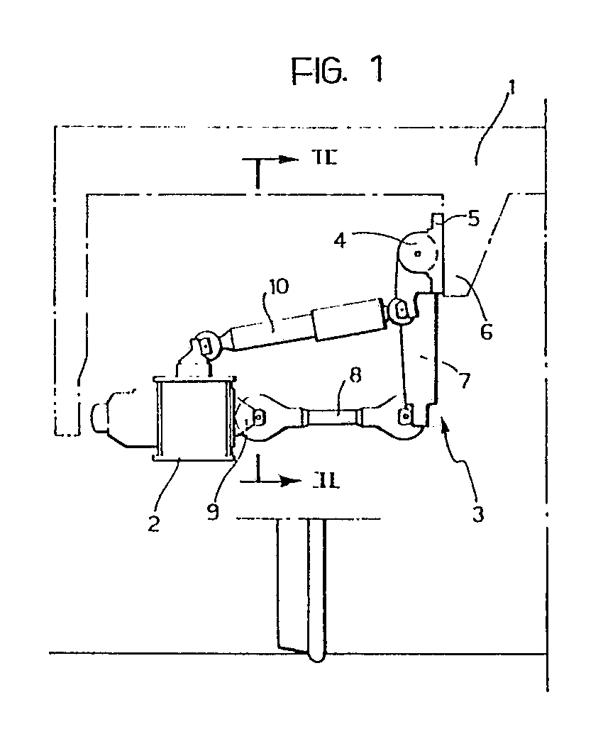
Figure 1 is a schematic cross-section of part of a railway vehicle provided with a
transverse suspension according to the invention, and
Figure 2 is a section taken on the line II-II of Figure 1.
[0008] With reference to the drawings, the lower part of the body of a railway vehicle is
schematically indicated 1 and a part of the structure of one of its bogies is indicated
2, a transverse suspension 3 according to the invention being interposed between them.
It should be noted that two suspensions 3 are normally associated with each of the
vehicle bogies and are situated symmetrically on opposite sides close to the sides
of the body 1.
[0009] The transverse suspension 3 comprises essentially a torsion bar 4 arranged parallel
to the longitudinal axis of the vehicle with its ends tightly fitted into a pair of
attachments 5 carried by a bracket 6 of the body 1. The upper end of a lever 7 is
keyed to the torsion bar 4 and is arranged substantially vertically, its lower end
being articulated to one end of a shaft 8 which is arranged substantially parallel
to the transverse axis of the vehicle. The opposite end of the shaft 8 is articulated
at 9 to the frame of the bogie 2.
[0010] In operation, the relative transverse movements between the body 1 and the bogie
2 are resiliently opposed by corresponding torsional deformations of the bar 4, achieved
by the transmission constituted by the lever 7 and the shaft 8.
[0011] The suspension 3 may also be equipped with a transverse shock-absorber 10 interposed
between the body 1 and the frame of the bogie 2 as shown in Figure 1.
1. A transverse suspension for railway vehicles, including a bogie and a body, characterised
in that it includes a torsion bar (4) mounted on one of the body and the bogie (1,
2) and means (7, 8) for connecting the torsion bar (4) to the other of the bogie and
the body (2, 1).
2. A suspension according to Claim 1, characterised in that the torsion bar (4) is
arranged parallel to the longitudinal axis of the vehicle with its ends fitted tightly
into attachments (5) fixed to the body (1), and in that the connection means comprise
a substantially vertical lever (7) with one end keyed to the central part of the torsion
bar (4) and a shaft (8) arranged substantially parallel to the transverse axis of
the vehicle with its ends articulated to the chassis of the bogie (2) and to the other
end of the lever (7) respectively.