| (19) |
 |
|
(11) |
EP 0 063 891 B1 |
| (12) |
EUROPEAN PATENT SPECIFICATION |
| (45) |
Mention of the grant of the patent: |
|
28.02.1990 Bulletin 1990/09 |
| (22) |
Date of filing: 08.04.1982 |
|
| (51) |
International Patent Classification (IPC)5: A61C 5/06 |
|
| (54) |
Ejector holder for capsule-like cartridge
Presse für eine kapselähnliche Patrone
Support-éjecteur pour cartouche analogue à une capsule
|
| (84) |
Designated Contracting States: |
|
CH DE FR GB IT LI SE |
| (30) |
Priority: |
09.04.1981 US 252558
29.01.1982 US 344254
29.01.1982 US 344255
|
| (43) |
Date of publication of application: |
|
03.11.1982 Bulletin 1982/44 |
| (60) |
Divisional application: |
|
84113283.0 / 0145922 |
| (73) |
Proprietor: DENTSPLY INTERNATIONAL, INC. |
|
York
Pennsylvania 17405 (US) |
|
| (72) |
Inventors: |
|
- Dougherty, Emery W.
York
Pennsylvania 17402 (US)
- Welsh, Richard E.
Milford
Delaware 19963 (US)
|
| (74) |
Representative: Wächtershäuser, Günter, Prof. Dr. |
|
Patentanwalt,
Tal 29
80331 München
80331 München (DE) |
| (56) |
References cited: :
BR-A- 5 701 465
GB-A- 298 292
US-A- 2 505 028
US-A- 3 184 120
US-A- 3 300 100
US-A- 3 534 735
US-A- 3 815 878
US-A- 3 907 106
US-B- 4 330 280
|
FR-A- 2 078 627
US-A- 1 926 496
US-A- 3 076 455
US-A- 3 220 412
US-A- 3 464 412
US-A- 3 581 399
US-A- 3 900 954
US-A- 4 198 756
|
|
| |
|
|
|
|
| |
|
|
|
Remarks: |
|
Divisional application 84113283 filed on 05.11.84. |
|
|
|
Remarks: |
|
The file contains technical information submitted after the application was filed
and not included in this specification |
|
| Note: Within nine months from the publication of the mention of the grant of the European
patent, any person may give notice to the European Patent Office of opposition to
the European patent
granted. Notice of opposition shall be filed in a written reasoned statement. It shall
not be deemed to
have been filed until the opposition fee has been paid. (Art. 99(1) European Patent
Convention).
|
[0001] This invention is directed to a manually operable ejector holder in combination (with
a cartridge) for use in connection with the ejection of viscous materials, especially
dental materials.
[0002] In recent years it has become popular to package various types of material, especially
medicinal or quasi-medicinal types in sealed cartridges, insertable in a suitable
type of holder and/or ejector device, for purposes of preserving purity of the medicament
and the like, insuring a patient of accurately measured quantities, as well as minimizing
effort now required in introducing bulk amounts of material into syringes and ejecting
measured quantities thereof, for example. Various previous efforts in this direction
are illustrated and described in various prior U.S. patents, particularly U.S. Patent
No. 3,581,399 to Dragan, dated June 1, 1971, in which a typical example of loaded
cartridge is illustrated in conjunction with one type of holder and discharge device.
[0003] Other efforts have been made to produce similar devices, one of these comprising
the subject matter of prior U.S. Patent No. 3,900,954, also to Dragan, dated Aug.
26, 1975, and comprising a simpler version than in Dragan's patent No. 3,581,399.
Also, another U.S. patent to Dragan, No. 4,198,756, dated April 22, 1980 shows an
ejector design for the aforementioned cartridges.
[0004] It has been found in the operation of the Dragan devices particularly relative to
the curved discharge end of the capsule or cartridges that there have been occasions
when the leading end of the ejecting plunger or the piston within the cartridge pushed
through the wall adjacent the outer end of the cartridge. Particularly for purposes
of obviating this difficulty and also for providing what is believed to be a simple
and improved compartment at the forward end of the barrel of the holder, as well as
also providing an improved cartridge not subject to the difficulties of Dragan's cartridges,
which is free of difficulties similar to those described with respect to the Dragan
cartridge, the present invention has been devised and details thereof are set forth
hereinbelow. Certain other constructions for cartridges of the type described above
are disclosed in U.S. Patent 2,505,028 to Boeger issued April 25, 1950.
[0005] MU-57 01 465 discloses a manually operable ejector holder comprising an elongate
barrel having a forward end provided with a longitudinal bore a plunger reciprocable
therein. The holder further comprises an element movable relative to the barrel for
moving the plunger.
[0006] U.S. 3 076 455 and U.S. 3 220 455 disclose a manually operable hypodermic syringe
for cap- suled medicaments. The syringe comprises a holder for securing a capsule,
plunger for forcing the composition from the capsule and an element movable relative
to the holder for moving the plunger.
[0007] The present invention also comprises a simplified improvement over U.S. patent No.
4,295,828 in the name of Helmut Rudler, dated October 20, 1981, and entitled 'Ejector
Holder for Syringe-type Cartridge', the invention covered thereby being assigned to
the same assignee as the invention of the instant application.
[0008] It is among the principal objects of the present invention to provide preferably
a one-piece barrel having integral and relatively simple means at the forward end
thereof to seat and retain an improved cartridge having an annular flange at the end
opposite the discharge end, said cartridge being retained by a simple snap-acting
arrangement.
[0009] It is another object of the invention to provide at the forward end of said barrel
a compartment or bore in which said aforementioned seat for the flange of the cartridge
is included, said compartment being formed simply by cutting away part of the wall
comprising the forward end of the barrel a limited distance inwardly and axially from
the outer end of the barrel, the surface formed by the cutaway arrangement lying within
a plane parallel to the axis and radially spaced from the same a short distance, the
inner end portion of the cutaway arrangement being wider than the portion extending
forwardly therefrom for purposes of receiving the flange of the cartridge in a seat
for said flange which is forwardly of the inner end of the compartment and into which
the flange is inserted to mount the cartridge in the compartment.
[0010] A further object of the invention is to provide in the compartment a semi-cylindrical
surface from which opposite, substantially parallel sidewalls extend and the upper
edges of said sidewalls extending a very limited distance toward each other and said
sidewalls having limited flexibility to provide the snap acting retaining arrangement
referred to above.
[0011] Still another object of the invention is to provide on the rearward end of the barrel
a handle fixed thereto and extending transversely thereto, preferably in opposite
direction from the axis of the barrel, a plunger being reciprocably mounted in the
barrel for engagement at one end with a combination closure plug and piston in a cartridge,
when mounted in the forward end of the barrel, and several embodiments of an actuating
lever are provided which respectively are a lever of the second class and are pivotally
associated with one end of said handle and extend from the pivot means thereof past
the opposite end of the plunger and engaging the same for reciprocation thereof, as
aforesaid, when the lever is manually activated toward the handle, spring means being
provided on the plunger to retract the same from engagement of the forward end thereof
with a cartridge.
[0012] Another object closely ancillary to the foregoing object is to provide one embodiment
of lever which has affixed pivot axis relative to one end of the handle, whereby the
mid-portion of the lever has a sliding engagement with the aforesaid opposite end
of the plunger, while another embodiment of lever has a slideable pivot fulcrum relationship
with the associated end of the handle and said opposite end of the plunger has a rocking
engagement with an intermediate portion of the lever.
[0013] Still another object of the invention, also ancillary to the several foregoing objects,
and especially the latter embodiment of lever which has a rocking engagement with
the opposite end of the plunger, is to provide an engagement between said opposite
end of the plunger and intermediate portion of said lever which is in the nature of
a partial ball and socket configuration, whereby the lever pivotally moves about the
centre of the partial ball-like member, while the slidable pivot fulcrum end of the
handle moves relative to the pivot axis thereof.
[0014] According to the present invention there is provided a manually-operable ejector
holder in combination with a cartridge loaded with viscous material and the cartridge
having a body having an annular collar on one end and a discharge tip on the front
end, said holder comprising an elongate barrel having forward and rearward ends, a
plunger reciprocable therein and one end thereof projecting beyond said rearward end
of said barrel, a handle connected to said rearward end of said barrel and extending
substantially transversely to the axis thereof, a lever manually operable relative
to said handle and barrel to reciprocate said plunger to the front end of said barrel
for engagement with the cartridge when disposed therein, and the forward end of the
barrel being cutaway longitudinally a limited distance from the forward extremity
to provide a compartment having sidewalls extending over more than 180°C, and the
outer portions of the sidewalls of said compartment having limited flexibility and
extending toward each other a slightly lesser distance than the diameter of said compartment
to effect a snap-acting retaining means for a first portion of the body of the cartridge
when inserted into said compartment, an undercut groove being formed in said compartment
within said sidewalls to receive the annular collar with the cartridge discharge tip
and a second portion of the body extending forward from the extremity of the barrel.
[0015] In a preferred embodiment the sidewalls of said compartment at the inner end thereof
are recessed laterally a greater distance than the diameter of the annular collar
on the cartridge to permit the collar thereon to be inserted into said compartment
incident to being positioned into said undercut groove and said undercut groove at
the upper ends thereof having opposite wall portions in said compartment extending
toward each other a limited distance less than the diameter of the annular cartridge
collar to provide a seat for said collar forward of the portion of said laterally
recessed portion of said sidewalls of said compartment and from which said collar
cannot be removed laterally.
[0016] According to one advantageous embodiment the lever is connected to one end of said
handle by pivotal means and extending from said pivotal means past said projecting
end of said plunger, said lever having an arcuate surface, intermediately of the ends
thereof, engaging said projecting end of said plunger.
[0017] A cartridge for use in the ejector holder of the present invention is the subject
of European Patent Application No. 0145922, which is a divisional application based
upon the present application.
[0018] The invention will now be described by way of example only with reference to the
several figures of the accompanying drawings in which:-
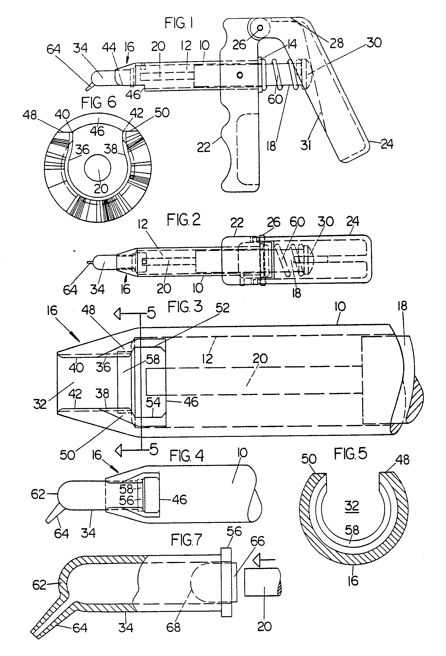
Figure 1 is a side elevation of an ejector holder supporting a capsule-like cartridge
in accordance with the principles of the present invention;
Figure 2 is a top plan view of the holder and cartridge shown in Figure 1;
Figure 3 is a fragmentary enlarged bottom plan view of the forward end of the barrel
of the ejector holder shown in Figures 1 and 2;
Figure 4 is a fragmentary bottom plan view of the ejector holder similar to Figure
3, but on a smaller scale, and illustrating a cartridge supported in the forward end
of the barrel;
Figure 5 is a vertical sectional view of the forward end portion of the barrel of
the ejector holder shown in Figure 3, as taken on section station 5-5 thereof;
Figure 6 is a front end view of the forward end of the barrel shown in Figures 1-4;
Figure 7 is a side elevation, partly broken away, of a cartridge similar to that shown
in Figures 1, 2 and 4, but on a larger scale, and illustrating a piston inserted in
the open end of the cartridge and also showing fragmentarily a portion of a plunger
rod of the ejector holder adapted to engage said piston;
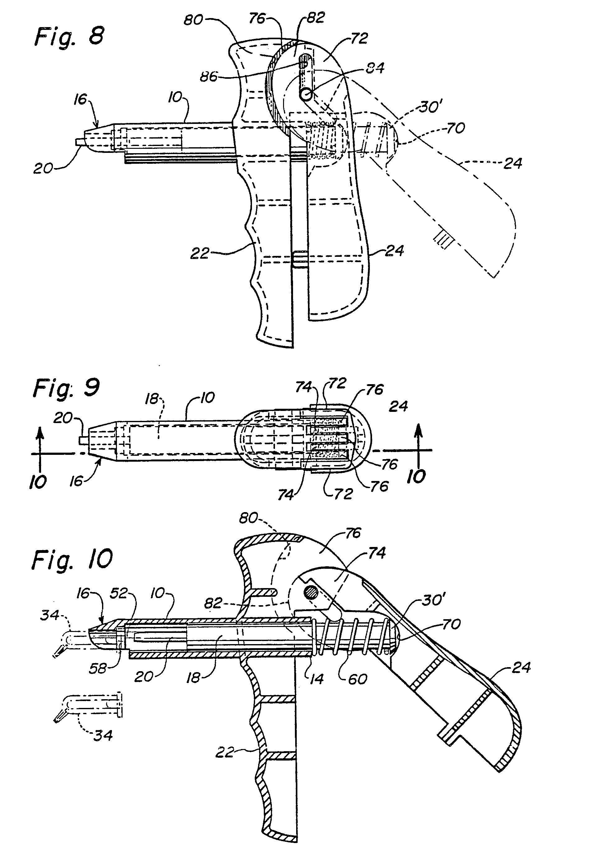
Figure 8 is a side elevation of another embodiment of ejector in accordance with this
invention;
Figure 9 is a top plan view of Figure 8; and
Figure 10 is a vertical section of Figure 9 as taken on section station 10-10 thereof.
[0019] Referring now to Figure 1, there is shown therein an ejector holder which includes
the principles of one embodiment of the present invention and comprising a barrel
10 having an interior bore 12 extending from the rearward end 14 of the barrel toward
the forward end 16 thereof for purposes of receiving a plunger 18 of the same diameter
as that of the interior bore 12 for the major portion of the length of the plunger,
the forward end of the plunger having a smaller diameter extension 20.
[0020] The rearward end 14 of the barrel 10 extends through and is fixed to a handle member
22 with which the barrel 10 is perpendicular. Pivotally connected to the handle 22
is an operating lever 24, the upper end of which is pivotally connected to the upper
end of handle 22 by a pivot pin 26 which is fixed relative to the upper end of handle
member 22. The upper end 28 of operating lever 24 is offset laterally to facilitate
operation of the lever 24 with respect to the outer end of plunger 18 which terminates
in a button 30, which is slidably engaged by a portion of the inner surface 31 of
operating lever 24.
[0021] From Figs. 1-4, it will be seen that the forward end 16 of the barrel 10 is tapered
and is provided with a longitudinally extending opening comprising compartment 32
which extends rearwardly from the terminal end of the forward end 16 toward the interior
bore 12. The lower surface of compartment 32, as viewed in Fig. 3, is semi- cylindrical
and is complementary to the elongated body of cartridge 34 so as to receive and seat
the same, as shown in Figs. 1, 2, and 4. The sidewalls 36 and 38 of compartment 32
extend upwardly from the semi-cylindrical bottom surface shown in Fig. 3 and are parallel
to each other for a limited distance and the upper edges 40 and 42 extend toward each
other a limited distance. Said uppermost portions of sidewalls 36 and 38 also have
limited flexibility, whereby the distance between the upper edges 40 and 42 of said
sidewalls preferably is slightly less than the diameter of the cartridge 34, whereby
there is a snap-acting retaining function provided by said sidewalls and the upper
edges 40 and 42 with respect to the cartridge 34 when the latter is inserted in the
compartment 32.
[0022] The forward end 16 of the barrel 10 also has a cutaway portion 44 extending longitudinally
rearward to form a shoulder 46, which determines the inner end of the cutaway portion.
Due to the fact that the forward end 16 is tapered and the barrel 10 otherwise is
circular, said cutaway arrangement provides flat surfaces 48 and 50. Also, as best
shown in Fig. 3, the sidewalls of the compartment 32, at the inner ends thereof, have
lateral recesses 52 and 54 which are spaced apart a greater distance than the diameter
of the annular exterior flange 56 in order to permit the insertion of the flange into
compartment 32 which, following radial insertion movement thereof into the compartment,
the cartridge may be moved axially forward for disposition of the flange 56 in an
undercut seat 58, which is clearly shown in Figs. 3-5. Said seat, in conjunction with
the portion of the compartment 32 extending forwardly therefrom, provides a firm means
for supporting a cartridge 34, which is retained seated in said compartment, especially
by means of the snap-fitting arrangement provided by the upper edges 40 and 42 of
the sidewalls 36 and 38, as described hereinabove. However, even if the snap-fitting
feature is omitted, the seat 58 will assure firm connection of the cartridge with
the barrel in use.
[0023] Without restriction thereto, the preferred material from which the barrel 10, handle
member 22 and operating lever 24 are formed, is a suitable rigid plastic material
in order that these elements may be formed readily and accurately by molding from
raw plastic material; obviously, the coiled spring 60 is formed from spring wire for
purposes of retracting the plunger 18 when the operating lever 24 is released, following
an ejection of material from the cartridge 34.
[0024] The cartridge 34 also is preferably formed by molding from appropriate, preferably
rigid, synthetic resin or plastic material by means of a suitable mold. The intermediate
body portion of the capsule 34 is of uniform interior and exterior diameter and extends
from the flange 56 adjacent the open end of the cartridge to the opposite closed end
62. The body portion is cylindrical, whereas the closed end 62 is hemispherical but
is provided with an angularly extending discharge nipple 64, the opening of which
is preferably a very fine dimension of small diameter. To effect ejection of material
from the cartridge 34, such as dental filling material, cement, or other viscous dental
material and the like, the cartridge 34 includes a piston 66, which is closely complementary
in diameter to the interior of the cartridge 34, and the inner end 68 thereof also
is hemispherical and complementary to the interior of the closed end 62 of the cartridge.
Without restriction thereto, the outer end of the piston may be flat for engagement,
for example, with the extension 20, shown fragmentarily in Fig. 7, when the plunger
18 is moved forwardly by actuation of the operating lever 24.
[0025] Removal of the capsule 34 from the compartment 32 is accomplished readily by snapping
the cartridge outwardly beyond the somewhat flexible upper edges 40 and 42 of the
compartment after the contents within the cartridge have been discharged or exhausted,
as required.
[0026] Another embodiment of ejector from that shown in Figs. 1-7 is illustrated in Figs.
8-10, both embodiments utilizing the cartridge-attaching means shown at the forward
or left-hand end of the barrel 10 as illustrated in Figs. 8-10 in the second embodiment
and, correspondingly, in Figs. 1-7 of the first embodiment. In Figs. 8-10, it will
be seen that the handle 24 is fixedly connected to the rearward end of the barrel
10 in the same manner as the corresponding element in Figs. 1-7. However, the operating
lever 24 is connected to the handle member 22 in a different manner from that illustrated
in Figs. 1-7, details of which are as follows:
[0027] The plunger 18 is reciprocable in the barrel 10 in opposite direction for purposes
of moving the extension 20 at the forward end thereof toward the cartridge 34 for
purposes of effecting discharge thereof. The rearward or right-hand end of the plunger
18, as viewed in Figs. 8 and 10, is provided with a button 30' which is slightly different
from the button 30 shown in Figs. 1-7, in that the same actually constitutes a part
of a ball and socket connection, of which the button 30' is a fragmentary ball or
at least functions as a fragmentary ball, the perimeter of which has a greater diameter
than that of the plunger 18 in order that the compression spring 60 may be disposed
with its opposite end respectively between the button 30' and the rearward end 14
of the barrel 10. The other part of the fragmentary ball and socket joint or connection
comprises a somewhat hemispherical seat 70 formed in the inner portion of the lever
24 intermediately of the ends thereof, whereby the modified button 30' actually comprises
a fulcrum about which the seat 70 rotates within the same plane as the handle 22 and
lever 24, the center of rotation being coincident with the axis of the plunger 18.
-
[0028] It has been found that movement of the lever 24 toward and from the handle 22 is
facilitated by the more-or-less fragmentary ball and socket joint or connection comprising
the button 30' and seat 70 when engaging the handle and lever somewhat in pistol-gripping
manner by one hand of an operator, especially when moving the lever 24 from the extended
position shown in Fig. 10 to the fully closed position shown in Fig. 8, the initial
position also being shown in Fig. 8 in phantom.
[0029] In order to permit the operation of the lever 24 in the manner just described, however,
the upper ends of both the hand 22 and lever 24 are modified from the arrangement
shown in the embodiment of Figs. 1-7, in the following respects:
[0030] Especially as shown in Fig. 9, it will be seen that the upper end of lever 24 is
provided with a plurality of similar parallel leaves 72 and 74, the leaves 72 being
outermost and the leaves 74 being disposed inwardly thereof. Interdigitated with the
leaves 72 and 74 of lever 24 are a plurality of three similar leaves 76 on the upper
end of handle 72. Further, the exterior side 78 of the upper end of handle 22 respectively
is provided with relatively shallow and flat arcuate sockets 80, see Fig. 8, to accommodate
the corresponding arcuate configurations 82 of lever 24.
[0031] In view of the pivotal movement of lever 24 about the axis of the modified button
30' and the plunger 18, it will be seen that the upper end of lever 24, which actually
is a lever of the second class, is provided with a floating fulcrum in the form of
a pin 84 which extends transversely through the leaves 76 of handle 22, and each of
the leaves 72 and 74 of the lever 24 are provided with slots 86 which are all parallel
to each other and commonly receive the pin 84 and thereby provide the aforementioned
floating fulcrum for the lever 24 and easier hand operation thereof.
[0032] From the foregoing, it will be seen that the several embodiments of ejector holders
and the particular type of cartridge to be used therewith are of very simple, but
highly effective design, to permit sure and quick mounting of the cartridge within
the compartment in the forward end of the barrel of the holder and, with equal facility,
removal of the cartridge therefrom is readily achieved. Assembly of all of the components,
particularly when manufactured by molding of suitable plastic or synthetic resin assures
accurate dimensions and the design of all the components is such that they are readily
capable of being formed by molding from plastic material.
[0033] Not only is the cartridge capable of serving as a receptacle for material to be discharged
when filled, for example, from a storage amount, but, even more importantly, the cartridge
can be filled at a factory with predetermined quantities of material and sealed therein
by application of the piston 66, which, under the circumstances, serves as a closure
for the cartridge. Further, during filling, air in the cartridge in advance of the
material can be discharged through the nipple 64 until filled and then the open end
of the nipple may suitably and inexpensively be closed by suitable seal means, such
as a small piece of sheet material having pressure-sensitive cement on one side and
fold said piece across the nipple in any suitable manner.
[0034] The cartridge may further comprise a preferably cup-shaped cap which is suitably
shaped either to frictionally engage the tip portion of the nipple 64, or either the
cap or nipple, or both, may have appropriate threads formed therein or thereon to
secure the cap releasably upon the tip of the nipple in sealed manner.
[0035] Moreover, the cap serves an important additional possible feature in that, in addition
to sealing the contents of the cartridge, in conjunction with the piston 66, the cap
also may be colour-coded for any of a number of purposes such as to indicate the kind
of material for specified purposes, weight or quantity of the material therein, setting
time, and otherwise.
[0036] Also, the body of the cartridge as well as the cap and piston 66 may all be molded
from similar plastic material which is coloured suitably to render the items opaque
or otherwise impervious to the transmission of ambient light which, if the contents
are subject to being set by such light, prevents premature setting thereof.
[0037] The foregoing description illustrates preferred embodiments of the invention. Other
modifications may, however, be employed without deviation from the invention as set
out in the claims.
1. A manually-operable ejector holder in combination with a cartridge (34) loaded
with viscous material and the cartridge having a body having an annular collar (56)
on one end and a discharge tip (64) on the front end, said holder comprising an elongate
barrel (10) having forward (16) and rearward (14) ends, a plunger (18) reciprocable
therein and one end (30) thereof projecting beyond said rearward end (14) of said
barrel (10), a handle (22) connected to said rearward end (14) of said barrel (10)
and extending substantially transversely to the axis thereof, a lever (24) manually
operable relative to said handle (22) and barrel (10) to reciprocate said plunger
(18) to the front end of said barrel (10) for engagement with the cartridge (34) when
disposed therein, and the forward end (16) of the barrel being cutaway longitudinally
a limited distance from the forward extremity to provide a compartment (32) having
sidewalls (36, 38) extending over more than 180°C, and the outer portions (40, 42)
of the sidewalls (36, 38) of said compartment (32) having limited flexibility and
extending toward each other a slightly lesser distance than the diameter of said compartment
(32) to effect a snap-acting retaining means for a first portion of the body of the
cartridge (34) when inserted into said compartment (32), an undercut groove (58) being
formed in said compartment (32) within said sidewalls (36,38) to receive the annular
collar (56) with the cartridge discharge tip (64) and a second portion of the body
extending forward from the extremity of the barrel (10).
2. The combination as claimed in claim 1 wherein the sidewalls (36, 38) of said compartment
(32) at the inner end thereof are recessed laterally (52, 54) a greater distance than
the diameter of the annular collar (56) on the cartridge to permit the collar (56)
thereon to be inserted into said compartment (34) incident to being positioned into
said undercut groove (58), and said undercut groove (58) at the upper ends thereof
having opposite wall portions in said compartment extending toward each other a limited
distance less than the diameter of the annular cartridge collar (56) to provide a
seat for said collar (56) forward of the portion of said laterally recessed portion
of said sidewalls (36, 38) of said compartment (32) and from which said collar (56)
cannot be removed laterally.
3. The combination as claimed in claim 1 or 2, wherein said lever (24) is connected
to one end of said handle (22) by pivotal means (26) and extends from said pivotal
means (26) past said projecting end (30) of said plunger (18), said lever (24) having
an arcuate surface (70) intermediately of the ends thereof engaging said projecting
end (30) of said plunger.
4. The combination as claimed in claim 1 characterised in that the sidewalls (36,
38) of said compartment (32) forwardly of said undercut groove (58) extend outwardly
in a radial direction from a semicylindrical innermost surface of uniform diameter
and the distance between said sidewalls (36, 38) being uniform throughout the length
thereof forwardly of said undercut groove (58).
5. The combination claimed in claim 3 characterised in that said arcuate surface (31)
has a centre of curvature coincident with the axis of said plunger (18) for pivotal
movement of said lever (24) relative thereto when said lever (24) is moved toward
said handle (22) to move said plunger (18) toward the forward end (16) of said barrel
(10).
6. The combination as claimed in claim 5 for extruding viscous dental material and
the like from said capsule like cartridge (34) via a discharge means (64) on one end
thereof characterised in that the lever (24) is of the second class and mounted adjacent
to said handle (22) and intermediately of the ends thereof, said lever having means
(31) engagable with said projecting end (30) of the plunger (18) in pivotal rocking
movement about the axis of said plunger (18) when said lever (24) is moved manually
toward said handle (22), and the pivotal means (26) between similar adjacent ends
of said handle (22) and lever (24) comprising interengaged pivot and slot means thereon
operable to permit said pivotal rocking movement of said lever (24) relative to said
projecting end (30) of said plunger (18).
7. The combination as claimed in claim 6 characterised in that said lever (24) and
projecting end (30) of said plunger (18) have interengaging partial ball and socket
means (30', 70) to effect said pivotal rocking movement therebetween, whereby manual
engagement of said lever (24) and handle (22) to move the same toward each other permits
a squeezing action substantially devoid of any sliding tendency in such manual contact
with said lever (24).
8. The combination as claimed in claim 7 characterised in that said pivotal means
on the ends of said lever and handle comprise a transverse pivot member (26) fixed
to one of the same and slots receiving said pivot member (26) being formed in the
other susbtantially longitudinally thereof.
9. The combination as claimed in claim 7 characterised in that the partial ball (30')
is on said projecting end of the plunger (18) and coaxial therewith, and the partial
socket (70) is formed in said lever (24) in a surface nearest said handle (22).
10. The combination as claimed in claim 9 characterised in that the partial ball (30')
on said plunger (18) has a circumference of greater diameter than the diameter of
said plunger (18), and a coiled spring (60) surrounds a portion of said plunger (18)
adjacent to said partial ball (30'), the opposite ends of said spring respectively
engaging said rearward end (14) of the barrel (10) and said partial ball (30').
11. The combination as claimed in claim 8 characterised in that said transverse pivot
member (26) is fixed to said handle (22) and said slots being formed in the adjacent
end of said lever (24), whereby said lever (24) is slidably pivotal relative to said
handle (22).
12. The combination as claimed in any preceding claim wherein the front end of the
body of the cartridge is closed by a hemispherical wall (62) of substantially uniform
thickness, the discharge tip (64) extends from said closed end (62) of said body at
an angle to the axis of said body, and there is a piston (66) having sidewalls closely
complementary to the inner walls of said body and inserted into the open end thereof
to form a combination closure and ejecting means for the material contained in said
cartridge (34).
13. The combination according to claim 12 wherein the inner end (68) of said piston
(66) is hemispherical and complementary in shape to the interior surface of the closed
end of said body to effect ejection of substantially the entire contents of said cartridge
(34) when said piston (66) is fully inserted into said body of the cartridge (34).
14. The combination according to claim 12 further characterised by said body and piston
being formed from plastic material suitably coloured to render the same impervious
to the transmission of ambient light, thereby rendering the cartridge adapted to contain
light-curable material and the like in a manner to prevent premature curing of such
material while stored in such cartridge.
15. The combination according to claim 12 further including sealing means (70) removably
connected to the outer end of the discharge tip (64) on said body to close said outer
end of the tip (64) to seal the contents of the cartridge (34) against ingress of
ambient atmosphere and/or any surrounding contaminating matter.
16. The combination according to claim 15 further characterised by said sealing means
comprising a cup-shaped cap (70) detachably connected to the outer end of said tip
(64).
17. The combination according to claim 16 further characterised by said cup-shaped
cap (70) being moulded from plastics material and connected to the outer end portion
of said tip (64) by thread means formed on one or both of the engaged surface portion
of said cap (70) and outer end of said tip (64).
18. The combination according to claim 15 further characterised by said sealing means
being colour-coded to indicate desired properties of the contents of the cartridge.
19. The combination according to claim 18 in which said sealing means is a cup-shaped
cap detachably connected to the outer end of said tip and colour-coded to indicate
desired properties of the contents of the cartridge.
1. Handbetätigbare Ejektorhaltereinrichtung in Kombination mit einer Patrone (34),
die mit Viskosematerial beladen ist und wobei die Patrone einen Körper mit einem ringförmigen
Kragen (56) an einem Ende und einer Auslaßspitze (64) auf der Frontseite aufweist,
wobei die Halteeinrichtung eine längliche Führungshülse (10) mit einem vorderen Ende
(16) und einem hinteren Ende (14) aufweist, einen Kolben (18), der darin verschiebbar
ist und dessen eines Ende (30) über das hintere Ende (14) der Führungshülse (10) herausragt,
einen Handgriff (22), der mit dem hinteren Ende (14) der Führungshülse (10) verbunden
ist und sich im wesentlichen transversal bezüglich deren Achse erstreckt, einen Hebel
(24), der relativ zu dem Handgriff (22) und der Führungshülse (10) manuell antreibbar
ist, um den Kolben (18) auf das vordere Ende der Führungshülse (10) hinzubewegen,
um ihm mit der darin angeordneten Patrone (34) in Eingriff zu bringen, und wobei das
vordere Ende (16) der Führungshülse in Längsrichtung mit einem begrenzten Abstand
von dem vorderen äußersten Ende weggeschnitten ist, um eine Kammer (32) zu schaffen,
mit Seitenwänden (36,38), die sich über mehr als 180° erstrecken, und die äußeren
Abschnitte (40, 42) der Seitenwände (36, 38) der Kammer (32) eine begrenzte Flexibilität
aufweisen und sich aufeinanderzu erstrecken, mit einem geringfügig kleineren Abstand
als der Durchmesser der Kammer (32), so daß eine Halteeinrichtung mit Schnappwirkung
für einen ersten Abschnitt des Körpers der Patrone (34) bewirkt wird, wenn diese in
die Kammer (32) eingesetzt ist, wobei eine Unterschnittnut (58) in der Kammer (32)
mit den Seitenwänden (36, 38) ausgebildet ist, zur Aufnahme des ringförmigen Kragens
(56), wobei sich die Patronenauslaßspitze (64) und ein zweiter Abschnitt des Körpers
vom äußersten Ende der Führungshülse (10) nach vorwärts erstrecken.
2. Die Kombination gemäß Anspruch 1, wobei die Seitenwände (36, 38) der Kammer (32)
an ihrem inneren Ende in lateraler Richtung (52, 54) um einen größeren Abstand zurückspringen
als der Durchmesser des ringförmigen Kragens (56) an der Patrone, damit der Kragen
(56) in die Kammer (32) im Zuge des Einsetztens in dieselbe in der Unterschnittnut
(58) positioniert wird und wobei die Unterschnittnut (58) an ihren oberen Enden gegenüberliegende
Wandbereiche in der Kammer aufweist, die sich aufeinanderzu erstrekken mit einem begrenzten
Abstand, der geringer ist als der Durchmesser des ringförmigen Patronenkragens (56)
unter Schaffung eines Sitzes für den Kragen (56) vor dem Abschnitt des erwähnten lateral
zurückspringenden Abschnitts der Seitenwände (36, 38) der Kammer (32) und aus dem
der Kragen (56) nicht lateral entfernt werden kann.
3. Die Kombination gemäß Anspruch 1 oder 2, wobei der Hebel (24) mit einem Ende des
Handgriffs (52) durch eine Gelenkeinrichtung (26) verbunden ist und sich von der Gelenkeinrichtung
(26) vorbei an dem vorspringenden Ende (30) des Kolbens (18) erstreckt, wobei der
Hebel (24) zwischen seinen Enden eine bogenförmige Oberfläche (70) aufweist, mit der
das vorspringende Ende (30) des Kolbens in Eingriff steht.
4. Die Kombination gemäß Anspruch 1, dadurch gekennzeichnet, daß sich die Seitenwände
(36, 38) der Kammer (321) vor der Unterschnittnut (58) von einer semizylindrischen
innersten Oberfläche mit einförmigen Durchmesser in einer radialen Richtung nach außen
erstrekken und der Abstand zwischen den Seitenwänden (36, 38) über die gesamte Länge
vor der erwähnten Unterschnittnut (58) einförmig ist.
5. Die Kombination gemäß Anspruch 3, dadurch gekennzeichnet, daß die bogenförmige
Oberfläche (70) ein Zentrum der Krümmung aufweist, die mit der Achse des Kolbens (18)
zusammenfällt, so daß die Hebelbewegung des Hebels (24) relativ zu der Achse beim
Hinbewegen des Hebels (24) auf den Handgriff (22) den Kolben (18) auf das vordere
Ende (16) der Führungshülse (10) hinbewegt.
6. Die Kombination gemäß Anspruch 5 zur Extrudierung von viskosem Dentalmaterial und
dergleichen aus der kapselartigen Patrone (34) via eine Auslaßeinrichtung (64) am
einen Ende derselben, dadurch gekennzeichnet, daß der Hebel (24) zur zweiten Klasse
gehört und benachbart des Handgriffs (22) befestigt ist und der Hebel zwischen seinen
Enden eine Einrichtung (31) aufweist, die mit dem vorspringenden Ende (30) des Kolbens
(18) drehbar angelenkt in Eingriff gebracht werden kann für eine Hin- und Herbewegung
der Achse des Kolbens (18), wenn der Hebel (24) manuell auf den Handgriff (22) hinbewegt
wird und wobei die Anlenkeinrichtung (26) zwischen ähnlichen benachbarten Enden des
Handgriffs (22) und dem Hebel (24) eine miteinander in Eingriff stehende Zapfen- und
Schlitzeinrichtung umfaßt, die in der Weise betrieben werden kann, daß eine drehbar
angelenkte Hin-und Herbewegung des Hebels (24) bezüglich des vorspringenden Endes
(30) des Kolbens (18) möglich ist.
7. Die Kombination gemäß Anspruch 6, dadurch gekennzeichnet, daß der Hebel (24) und
das vorspringende Ende (30) des Kolbens (18) miteinander in Eingriff stehende teilweise
Kugel-und Schaleneinrichtung (30', 70) aufweisen, um die erwänte drehbar gelagerte
Hin- und Herbewegung zwischen denselben zu bewirken, wobei das manuelle Ineingriffbringen
des Hebels (24) und des Handgriffs (22) unter Bewegung derselben aufeinanderzu es
gestattet, eine Quetschwirkung auszuüben, die im wesentlichen frei ist von irgendeiner
Abgleittendenz bei einem derartigen manuellen Kontakt mit dem Hebel (24).
8. Die Kombination gemäß Anspruch 7, dadurch gekennzeichnet, daß die Lagereinrichtungen
am Ende des Hebels und im Handgriff ein transversales Zapfenorgan (26) umfassen, das
an einem der Bauteile befestigt ist und wobei Schlitze zur Aufnahme des Zapfenorgans
(26) in dem anderen der Bauteile im wesentlichen in Längsrichtung desselben ausgebildet
sind.
9. Die Kombination gemäß Anspruch 7, dadurch gekennzeichnet, daß die Teilkugel (30')
auf dem vorspringenden Ende des Kolbens (18) und koaxial mit demselben ausgebildet
ist und die Teilschale (70) in dem Hebel (24) in der Oberfläche, die dem Handgriff
(22) am nächsten liegt, ausgebildet ist.
10. Die Kombination gemäß Anspruch 9, dadurch gekennzeichnet, daß die Teilkugel (30')
einen Umfangskreis mit größerem Durchmesser als der Durchmesser des Kolbens (18) aufweist
und eine Federwendel (60) einen Abschnitt des Kolbens (18) benachbart der Teilkugel
(30') umgibt, wobei die entgegengesetzten Enden der Feder jeweils mit dem hinteren
Ende (14) der Führungshülse (10) bzw. mit der Teilkugel (30') in Eingriff stehen.
11. Die Kombination gemäß Anspruch 8, dadurch gekennzeichnet, daß das transversale
Zapfenorgan (26) an dem Handgriff (24) fixiert ist und die Schlitze in dem benachbarten
Ende des Hebels (24) ausgebildet sind, so daß der Hebel (24) bezüglich des Handgriffs
(22) verschiebbar angelenkt ist.
12. Die Kombination gemäß einem der vorstehenden Ansprüche, wobei das vordere Ende
des Körpers der Patrone durch eine halbkugelförmige Wand (62) mit im wesentlichen
einförmiger Dicke verschlossen ist, die Auslaßspitze (64) sich von dem verschlossenen
Ende (62) des Körpers in einem Winkel bezüglich der Achse des Körpers erstreckt und
ein Kolben (66) mit Seitenwänden in enger Komplementärbeziehung zu den Innenwänden
des Körpers vorgesehen ist und in das offene Ende des Körpers eingesetzt ist zur Ausbildung
einer Kombination von Schließ- und Ausdrückeinrichtungen für das in der Patrone enthaltene
Material.
13. Die Kombination gemäß Anspruch 12, wobei das innere Ende (68) des Kolbens (66)
halbkugelförmig und mit einer komplementären Gestalt bezüglich der inneren Oberfläche
des verschlossenen Endes des Körpers ausgebildet ist, um das Ausdrücken von im wesentlichen
dem gesamten Inhalt der Patrone (34) zu bewirken, wenn der Kolben (66) vollständig
in den Körper der Patrone (34) eingeschoben ist.
14. Die Kombination gemäß Anspruch 12, weiter gekennzeichnet dadurch, daß der Körper
und der Kolben aus Kunststoffmaterial gefertigt sind, das in geeigneter Weise angefärbt
ist, um dasselbe gegen die Transmission vom Umgebungslicht undurchdringlich zu machen,
um auf diese Weise die Patrone zur Aufnahme von lichthärtbarem Material und dergleichen
geeignet zu machen durch Verhinderung eines vorzeitigen Härtens eines derartigen Materials
bei der Lagerung in einer derartigen Patrone.
15. Die Kombination gemäß Anspruch 12, weiter umfassend Abdichteinrichtungen (70),
die entfernbar mit dem äußeren Ende der Auslaßspitze (64) des Körpers verbunden sind,
um das äußere Ende der Spitze (64) zu verschließen und den Inhalt der Patrone (34)
gegen das Eintreten von Umgebungsatmosphäre und/oder irgendwelchen Verunreinigungen
der Umgebung zu schützen.
16. Die Kombination gemäß Anspruch 15, weiter gekennzeichnet dadurch, daß die Abdichteinrichtung
eine hütchenförmige Kappe (70) umfaßt, die entfernbar mit dem äußeren Ende der Spitze
(64) verbunden ist.
17. Die Kombination gemäß Anspruch 16, weiter gekennzeichnet dadurch, daß die hütchenförmige
Kappe (70) aus Kunststoffmaterial gefertigt ist und mit dem äußeren Endabschnitt der
Spitze (64) durch Schraubeinrichtungen verbunden ist, die auf einem oder beiden der
miteinander in Eingriff stehenden Oberflächenbereiche der Kappe (70) und des äußeren
Endes der Spitze (64) ausgebildet sind.
18. Die Kombination gemäß Anspruch 15, weiter gekennzeichnet dadurch, daß die Abdichteinrichtungen
eine Farbcodierung aufweisen, um die gewünschten Eigenschaften des Inhalts der Patrone
anzuzeigen.
19. Die Kombination gemäß Anspruch 18, wobei die Abdichteinrichtung eine hütchenförmige
Kappe ist, die entfernbar mit dem äußeren Ende der Spitze verbunden ist und eine Farbcodierung
aufweist, um gewünschte Eigenschaften des Inhalts der Patrone anzuzeigen.
1. Porte-éjecteur actionnable manuellement en combinaison avec une cartouche (34)
chargée d'un matériau visqueux et la cartouche possédant un corps ayant un collier
annulaire (56) sur une extrémité et une pointe de distribution (64) sur l'extrémité
antérieure, ledit porte-éjecteur comportant un barillet allongé (10) possédant des
extrémités antérieure (16) et postérieure (14), un plongeur (18) pouvant aller et
venir à l'intérieur et une extrémité (30) de celui-ci faisant saillie au-delà de ladite
extrémité postérieure (14) dudit barillet (10), une poignée (22) reliée à ladite extrémité
postérieure (14) dudit barillet (10) et s'étendant sensiblement transversalement à
l'axe de celui-ci, un levier (24) actionnable manuellement par rapport à ladite poignée
(22) et audit barillet (10) pour faire aller et venir ledit plongeur (18) jusqu'à
l'extrémité antérieure dudit barillet (10) pour un contact avec la cartouche (34)
lorsqu'elle est disposée à l'intérieur, et l'extrémité antérieure (16) du barillet
étant évidée longitudinalement sur une distance limitée à partir de l'extrémité antérieure
pour constituer un compartiment (32) possédant des parois latérales (36, 38) s'étendant
sur plus de 180°, et les parties extérieures (40, 42) des parois latérales (36, 38)
dudit compartiment (32) possédant une flexibilité limitée et s'étendant l'une vers
l'autre sur une distance légèrement moindre que le diamètre dudit compartiment (32)
pour constituer un organe de retenue par encliquetage pour une première partie du
corps de la cartouche (34) lorsqu'elle est introduite dans ledit compartiment (32),
une gorge évidée (58) étant pratiquée dans ledit compartiment (32) à l'intérieur desdites
parois latérales (36,38) pour recevoir le collier annulaire (56) avec la pointe de
distrubution (64) de la cartouche et une seconde partie du corps s'étendant vers l'avant
depuis l'extrémité du barillet (10).
2. Combinaison seion la revendication 1, dans laquelle les parois latérales (36, 38)
dudit compartiment (32) à l'extrémité intérieure de celui-ci sont évidées latéralement
(52, 54) sur une distance supérieure au diamètre du collier annulaire (56) sur la
cartouche pour permettre au collier (56) sur celle-ci d'être introduit dans ledit
compartiment (32) disposé dans ladite gorge évidée (58), et ladite gorge évidée (58)
à ses extrémités possédant des parties de parois opposées dans ledit compartiment
s'étendant l'une vers l'autre sur une distance limitée inférieure au diamètre du collier
de cartouche annulaire (56) pour constituer un siège pour ledit collier (56) en avant
de la partie de ladite partie évidée latéralement desdites parties latérales (36,
38) dudit compartiment (32) et à partir duquel ledit collier (56) peut être retiré
latéralement.
3. Combinaison selon la revendication 1 ou 2, dans laquelle ledit levier (24) est
relié à une extrémité de ladite poignée (22) par un organe pivotant (26) et s'étend
depuis ledit organe pivotant (26) devant ladite extrémité saillante (30) dudit plongeur
(18), ledit levier (24) possédant une surface arquée (70) entre ses extrémités en
contact de ladite extrémité saillante (30) dudit plongeur.
4. Combinaison selon la revendication 1, caractérisée en ce que la parois latérales
(36, 38) dudit compartiment (32) en avant de ladite gorge évidée (58) s'étendent vers
l'extérieur dans une direction radiale depuis une surface interne semi- cylindrique
de diamètre uniforme et la distance entre lesdites parois latérales (36, 38) étant
uniforme sur toute leur longueur en avant de ladite gorge évidée (58).
5. Combinaison selon la revendication 3, caractérisée en ce que ladite surface arquée
(31) possède un centre de courbure coïncidant avec l'axe dudit plongeur (18) en vue
d'un mouvement de pivotement dudit levier (24) par rapport à celui-ci lorsque ledit
levier (24) est déplacé vers ladite poignée (22) pour déplacer ledit plongeur (18)
vers l'extrémité antérieure (16) dudit barillet (10).
6. Combinaison selon la revendication 5, en vue d'extruder un matériau dentaire visqueux
et analogues à partir de ladite cartouche (34) analogue à une capsule par l'intermédiaire
d'un organe de distribution (64) sur une de ses extrémités, caractérisée en ce que
le levier (24) est du second ordre et monté adjacent à ladite poignée (22) et entre
les extrémités de celle-ci, ledit levier possédant des moyens (31) pouvant venir en
contact de ladite extrémité saillante (30) du plongeur (18) au cours d'un mouvement
de basculement pivotant autour de l'axe dudit plongeur (18) lorsque ledit levier (24)
est déplacé manuellement vers ladite poignée (22), et les organes de pivotement (36)
entre des extrémités adjacentes similaires de ladite poignée (22) et du levier (24)
comportant des moyens de pivotement et de fente en contact les uns des autres sur
celui-ci, actionnables pour permettre ledit mouvement de basculement pivotant dudit
levier (24) par rapport à ladite extrémité saillante (30) dudit plongeur (18).
7. Combinaison selon la revendication 6, caractérisée en ce que ledit levier (24)
et l'extrémité saillante (30) dudit plongeur (18) possèdent des joints à rotule partiels
s'interpénétrant (30', 70) pour effectuer ledit mouvement de basculement pivotant
entre eux, de telle sorte qu'un contact manuel dudit levier (24) et de la poignée
(22) pour les déplacer l'un vers l'autre permet une action de compression sensiblement
exempte d'une tendance quelconque au glissement dans un tel contact manuel avec ledit
levier (24).
8. Combinaison selon la revendication 7, caractérisée en ce que lesdits moyens pivotants
sur les extrémités dudit levier et de la poignée comportent un pivot transversal (26)
fixé à l'un d'eux et des fentes recevant ledit pivot (26) étant pratiquées dans l'autre
sensiblement longitudinalement à celui-ci.
9. Combinaison selon la revendication 7, caractérisée en ce que la bille partielle
(30') se trouve sur ladite extrémité saillante du plongeur (18) et coaxiale avec lui,
et la douille partielle (70) est réalisée dans ledit levier (24) dans une surface
la plus proche de ladite poignée (22).
10. Combinaison selon la revendication 9, caractérisée en ce que la bille partielle
(30') sur ledit plongeur (18) possède une circonférence de diamètre supérieure au
diamètre dudit plongeur (18), et un ressort hélicoïdal (60) entoure une partie dudit
plongeur (18) adjacente à ladite bille partielle (30'), les extrémités opposées dudit
ressort étant en contact respectivement de ladite extrémité postérieure (14) du barillet
(10) et ladite bille partielle (30').
11. Combinaison selon la revendication 8, caractérisé, en ce que ledit pivot transversal
(26) est fixé à ladite poignée (22) et lesdites fentes étant réalisées dans l'extrémité
adjacente dudit levier (24), de telle sorte que ledit levier (24) puisse pivoter à
coulissement par rapport à ladite poignée (22).
12. Combinaison selon l'une quelconque des revendications précédentes, dans laquelle
l'extrémité antérieure du corps de la cartouche est fermée par une paroi hémisphérique
(62) d'épaisseur sensiblement uniforme, la pointe de distribution (64) s'étend depuis
ladite extrémité fermée (62) dudit corps selon un angle par rapport à l'axe dudit
corps, et un piston (66) étant prévu possédant des parois latérales étroitement complémentaires
aux parois internes dudit corps et introduites dans l'extrémité ouverte de celui-ci
pour former une enceinte de la combinaison et des moyens d'éjection pour le matériau
contenu dans ladite cartouche (34).
13. Combinaison selon la revendication 12, dans laquelle l'extrémité interne (68)
dudit piston (66) est hémisphérique et de forme complémentaire à la surface interne
de l'extrémité fermée dudit corps pour effectuer l'éjection de pratiquement la totalité
du contenu de ladite cartouche (34) lorsque ledit piston (66) est complètement introduit
dans ledit corps de la cartouche (34).
14. Combinaison selon la revendication 12, caractérisée en outre par ledit corps et
ledit piston réalisés en matière plastique colorée de façon appropriée pour la rendre
opaque à la transmission de lumière ambiante, rendant ainsi la cartouche apte à contenir
un matériau photopolymé- risable et analogues de manière à empêcher un durcissement
prématuré de ce matériau lorsqu'il est stocké dans cette cartouche.
15. Combinaison selon la revendication 12, comprenant en outre des moyens d'étanchéité
(70) reliés de façon amovible à l'extrémité extérieure de la pointe de distribution
(64) sur ledit corps pour fermer ladite extrémité extérieure de la pointe (64) pour
protéger le contenu de la cartouche (34) contre une pénétration de l'atmosphère ambiante
et/ou d'une matière contami- nante environnante quelconque.
16. Combinaison selon la revendication 15, caracatérisée en outre en ce que lesdits
moyens d'étanchéité comportent un bouchon en forme de coupe (70) relié de façon détachable
à l'extrémité extérieure de ladite pointe (64).
17. Combinaison selon la revendication 16, caractérisée en outre en ce que ledit bouchon
en forme de coupe (70) est en matière plastique moulée et relié à l'extrémité extérieure
de ladite pointe (64) par un filetage réalisé sur l'une ou les deux de la surface
en contact dudit bouchon (70) et de l'extrémité extérieure de ladite pointe (64).
18. Combinaison selon la revendication 15, caractérisée en outre en ce que lesdits
moyens d'étanchéité portent un code de couleur pour indiquer les propriétés désirées
du contenu de la cartouche.
19. Combinaison selon la revendication 18, dans laquelle lesdits moyens d'étanchéité
sont un bouchon en forme de coupe relié de façon amovible à l'extrémité extérieure
de ladite pointe et coloré selon un code pour indiquer les propriétés désirées du
contenu de la cartouche.