| (19) |
 |
|
(11) |
EP 0 140 924 B1 |
| (12) |
EUROPEAN PATENT SPECIFICATION |
| (45) |
Mention of the grant of the patent: |
|
28.02.1990 Bulletin 1990/09 |
| (22) |
Date of filing: 19.03.1984 |
|
| (51) |
International Patent Classification (IPC)5: B65D 8/04 |
| (86) |
International application number: |
|
PCT/US8400/413 |
| (87) |
International publication number: |
|
WO 8403/873 (11.10.1984 Gazette 1984/24) |
|
| (54) |
IMPROVED METHOD AND APPARATUS FOR MAKING A NECKED CONTAINER
VERFAHREN UND VORRICHTUNG ZUM HERSTELLEN VON BEHÄLTERN MIT HALS
PROCEDE ET APPAREIL AMELIORES POUR FABRIQUER UN CONTENEUR A COL
|
| (84) |
Designated Contracting States: |
|
AT BE CH DE FR GB LI NL |
| (30) |
Priority: |
28.03.1983 US 479190
|
| (43) |
Date of publication of application: |
|
15.05.1985 Bulletin 1985/20 |
| (73) |
Proprietor: Präzisions-Werkzeuge AG |
|
8630 Rüti (CH) |
|
| (72) |
Inventors: |
|
- STOFFEL, Hans F.
Rye, NY 10580 (US)
- SAUNDERS, William T.
Weirton, WV 26062 (US)
- SPORRI, Anthony J.
Tallapoosa, GA 30176 (US)
|
| (74) |
Representative: Troesch, Jacques J., Dr. sc. nat. et al |
|
Troesch Scheidegger Werner AG
Siewerdtstrasse 95
8050 Zürich
8050 Zürich (CH) |
| (56) |
References cited: :
US-A- 1 698 999
US-A- 3 757 558
US-A- 3 808 868
US-A- 3 951 083
US-A- 3 995 572
US-A- 4 403 493
|
US-A- 3 581 542
US-A- 3 786 957
US-A- 3 898 828
US-A- 3 964 413
US-A- 4 261 193
|
|
| |
|
|
|
|
| |
|
| Note: Within nine months from the publication of the mention of the grant of the European
patent, any person may give notice to the European Patent Office of opposition to
the European patent
granted. Notice of opposition shall be filed in a written reasoned statement. It shall
not be deemed to
have been filed until the opposition fee has been paid. (Art. 99(1) European Patent
Convention).
|
[0001] The present invention relates to a method of forming a neck on a tubular member whereby
said tubular member is applied to a mandrel set having a dome-shaped pressing surface
set whereby the diameter of a free end portion of the tubular member is reduced and
there is formed along said pressing surface set an intermediate portion of said member
between said reduced diameter free end portion and the remainder of the member, the
area of dome-shaped pressing surface set of the mandrel set available for cooperation
with the tubular member is then at least once enlarged and the diameter of said free
end portion is at least once further reduced, so that said intermediate portion along
said enlarged pressing surface of said set is at least once increased.
[0002] In the past, there have generally been two basic kinds of necked aerosol containers:
those made of steel sheet material such as tin plate, and those made of aluminum.
In the case of steel sheet material, one form of construction for the aerosol containers
has been the three-piece container having a cylindrical container body with a longitudinally
extending soldered or welded lap joint and with a dome-shaped top and a bottom seamed
thereon. Steel sheet material aerosol containers have also been formed out of flat
steel sheet by a method called drawn and ironed. On such cans, a dome-shaped top is
mounted to form a two-piece container. Another drawn and ironed technique involves
forming a steel cup, cutting a hole in the cup and curling the adjacent edge to form
a necked top and then seaming a bottom to the cup.
[0003] Necked aerosol containers of aluminum may be made by a method which involves forming
so-called monoblocs from an aluminum slug into a cup. The top of the cup is formed
with a relatively small opening and an outside curl on which an aerosol valve is mounted.
A drawn and ironed process may also be used to form aluminum aerosol containers from
flat sheets of aluminum. A two-piece aluminum can formed by such a method has a dome-shaped
top which is mounted the same way as on a tin plate three-piece container. Aluminum
aerosol containers may also be integrally formed with a top having a relatively small
opening for an aerosol valve and with the bottom of the container being seamed on
to form a two-piece container.
[0004] Thus, it is known to make necked aerosol containers either by providing a cylindrical
container body with a special end or by shaping the end of a container particularly
when the container is formed of readily workable metal, such as aluminum. However,
until recently, the forming of a dome from a steel can body has been impractical from
a commercial standpoint.
[0005] The US=A-4,261,193 discloses a method as stated above. A mandrel arrangement comprises
a set of mandrels formed by a plurality of mandrels each having a dome-shaped pressing
surface, thus forming a set of such surfaces. A tubular member to be necked-in is
arranged over a first of these mandrels with a first dome-shaped pressing surface
and a respective outside tool is moved towards this mandrel so that the tubular member
is necked-in along said pressing surface between the remainder of said member and
the free end portion of the tubular member, the diameter of which being reduced by
this necking-in step. Then the tubular member is removed from this first mandrel and
is arranged on a second mandrel with an enlarged dome-shaped pressing surface. A second
respective outside tool cooperates with this second mandrel so as to enlarge along
said enlarged pressing surface the necked-in intermediate part of the tubular member
whereby the diameter of the free end portion of the tubular member is further reduced.
The necking-in operation is continued by successively removing the tubular member
from a previous mandrel and arranging it to a further mandrel with enlarged pressing
surface and acting with the respective outside tools on the member, thus progressively
enlarging the necked-in intermediate portion of the member and reducing its free end
portion diameter.
[0006] The US patent mentioned provides such method especially for necking-in steel aerosol
containers the tubular body being formed by overlap-welding the longitudinally extending
edges of a steel sheet which has been formed into a cylindrical configuration.
[0007] This known method acts on cylindrical container bodies with overlapped edges welded
together by a conventional welding process such as electrical resistence welding.
On such a welded cylindrical can body the wall thickness of the can body is greater
at the welded seam than it is elsewhere about the circumference of the can body. Thus
by this method necking of the container body is problematical in that it is not commercially
feasible to accurately orient the lap weld seam on the different mandrels of the mandrel
arrangement for successive necking operations. In the apparatus disclosed in this
patent it is therefore necessary for treating lap-welded members that the outside
tools be permitted to float radially in order to maintain the required clearance at
all circumferential points between the tools at each step of necking.
[0008] This known method for making a necked container is disadvantageous in that it requires
successive appliance and removal of the tubular member on different mandrels of the
mandrel arrangement, so that the tubular member must be transferred from one mandrel
to the other for progressive necking-in operations. This results in a relatively slow
process subject to damaging either the member or the tools. This general disadvantage
further makes it, as was mentioned, necessary to have the pressing tools floating
radially with respect to each other if lap-welded members shall be necked-in.
[0009] It is the object of the present invention to provide a method which avoids the aforementioned
disadvantage.
[0010] This object is resolved by the method as defined in claim 1.
[0011] An apparatus for progressively necking-in an end portion of a tubular member by this
method is defined in claim 9.
[0012] The fact that the inventive method and apparatus provides for only one mandrel whereon
the tubular member to be necked-in is arranged for all necking-in steps makes it possible
to more precisely control necking-in and further gives the possibility to commercially
provide for more necking-in steps.
[0013] These and other advantages of the present invention will become more apparent from
the following description when taken in connection with the accompanying drawings
which show, for purposes of illustration only, several embodiments in accordance with
the invention. In the figures
Figure 1 is a side elevational view of one embodiment of an aerosol container made
with the method and the apparatus of the invention;
Figure 2 is a sectional view taken through the portion of the upper, necked end of
a butt-welded tubular member which has been necked-in to form an aerosol container
as shown in Figure 1 and wherein the tubular member is shown in the various positions
as it is progressively necked-in;
Figure 3 is a sectional view of one embodiment of an apparatus of the invention for
making the aerosol container shown in Figure 1 and wherein the press ram is shown
in its upper position;
Figure 3a shows the apparatus according to Figure 3 in its lower position;
Figure 3b shows an enlarged portion of the apparatus according to Figure 3 with a
tubular member introduced;
Figure 4a is a schematic illustration of one side of the upper portion of a tubular
member which has been necked-in to form an aerosol container as shown in Figure 1;
Figure 4b is a schematic illustration similar to Figure 4a and graphically illustrating
trimming of the free end of the upper necked-in portion of the tubular member;
Figure 4c is a schematic illustration similar to Figure 4b and illustrating the trimmed
tubular member after the necked-in portion has been beaded inwardly;
Figure 4d is a schematic illustration similar to Figure 4c and wherein the upper end
of the necked-in tubular member is curled inwardly; and
Figure 5 is a cross sectional view of the container of Figure 1 taken along the line
V-V.
[0014] Referring now to the drawings, it will be seen that there is illustrated in Figure
1 a necked container 1 suitable for use as an aerosol can. The container 1 has an
appearance like that of an aluminum aerosol can produced from the so-called monoblocs
or by a drawn and ironed process, but differs therefrom in that the can body 2 is
made by a method, wherein a sheet of material is formed into a generally cylindrical
tubular member and the adjacent longitudinally extending edges thereof are butt welded
to form the side seam 3 and thereafter the welded tubular member is arranged about
a mandrel and an end portion thereof progressively necked-in over a dome-shaped surface
of the mandrel as discussed more fully below. The upper, necked-in end of the welded
tubular body 2 is necked-in to a diameter which is reduced by at least approximately
15% from the original diameter of the tubular member, and, more particularly, in the
disclosed embodiment, is reduced to a diameter on the order of one-half of the diameter
of the tubular member, with the necked-in end having a smooth dome-shaped configuration.
The upper free end of the necked-in welded tubular member is curled as shown at 5
for receiving a conventional aerosol valve assembly (not shown) which may be secured
to the upper end of the tubular member by a conventional seam.
[0015] As illustrated in Figure 1, the container body 2 is cylindrical over a major portion
of its height with the lower end thereof being closed by a conventional end unit 6
secured to the body 2 by means of a conventional seam 7. The sheet material used to
form the can body 2 is a plain low carbon steel sheet metal such as a single reduced,
T-4CA, 34kg (75 lb.) per base box material having a thickness of 0,2mm (.0083 inch).
A double reduced material, such as DR-8 or DR-9, could also be used where a higher
tensile strength is desired. Flat blanks of this sheet material are formed into a
generally cylindrical configuration with the opposed longitudinally extending edges
in abutting relationship for laser butt welding by a Z-bar guide apparatus, as disclosed
in U.S. Patent Nos. 4,272,004 and 4,354,090. These apparatus have only recently made
possible the successive, high-speed laser butt welding of the longitudinally extending
edges of tubular members.
[0016] An apparatus of the invention for progressively necking-in an end portion of e.g.
a butt welded tubular member is generally designated as 8 in Figure 3. The apparatus
comprises a first inside tool in the form of a stationary cylindrical supporting mandrel
9 of a first diameter. The upper, free end portion of the mandrel has a smooth dome-shaped
surface 10 with a radius of curvature of 3,81cm (1.5 inches) in the case of necking
a welded tubular member 5,28cm (2.080 inches) in diameter. The juncture 11 between
the dome-shaped surface 10 and the cylindrical side wall portion of the mandrel 9
is provided with a radius of curvature of 0,32cm (.125 inch). The apparatus 8 further
includes a plurality of second inside tools or knockout plugs 12, each having a second
diameter which is less than the first diameter of the mandrel 9 and having a lower,
free end portion 13 for positioning adjacent the dome-shaped surface 10 of mandrel
9 with the dome-shaped surface extending between the outer diameter of the mandrel
9 and the diameter of the knockout plug 12. The shape of the knockout plug 12 is changed
with each progressive diameter change or necking-in step as discussed below.
[0017] In particular, the outer diameter of the cylindrical knockout plugs 12 progressively
decrease with each necking-in step, so that the extent of the dome-shaped surface
between the outer diameter of the mandrel 9 and the knockout plug progressively increases.
[0018] The apparatus 8 further includes a plurality of outside tools generally designated
at 14 cooperable with the mandrel 9 and respective ones of the knockout plugs 12 during
necking-in of the end portion of a tubular member. While only one of the outside tools
14 and cooperating knockout plug 12 are shown in the drawings, it is understood that
the apparatus comprises a plurality of sets or pairs of these tools, which may be
mounted about a circle on a turret, for example, or in a straight line on a suitable
press as discussed hereinafter for successive use as will be readily apparent to the
skilled artisan. However, since a single mandrel 9 is used with each necking-in step,
it is not necessary to remove the tubular member from about the mandrel during the
various steps of the process. The necking-in of the tubular member can thus be accomplished
in a simpler and faster manner, subject to less damage as compared with the prior
art and without requiring mounting of the outside tools so as to float radially.
[0019] Each outside tool 14 includes a die piece 15 and a die insert 16 whose size or shape
changes with each progressive diameter change or necking-in step. Each of the plurality
of outside tools 14 have an internal configuration with a first cylindrical portion
cooperable with the outer diameter of the cylindrical mandrel 9, a second inwardly
tapered portion 18 cooperable with the dome-shaped surface 10 extending between the
outer diameter of the mandrel 9 and the outer diameter of the adjacent knockout plug
12, and a third portion in the form of a cylindrical surface cooperable with the outer
diameter of one of the knockout plugs 12.
[0020] As depicted in Figures 3, 3a, an outside tool 14 and a cooperable knockout plug 12
are mounted on a press ram 20 of a standard 350N straight side punch press for movement
with respect to the stationary mandrel 9. The knockout plug 12 of the cooperable pair
is normally biased in a leading and relatively movable position with respect to its
associated outside tool 14, as illustrated in Figure 3. With downward movement of
the press ram 20, the knockout plug 12 reaches a position adjacent the dome-shaped
surface 10 of the mandrel 9 while the outside tool 14 continues to move with respect
to both the knockout plug 12 and the mandrel 9 for effecting necking-in of the end
portion of the tubular member. In particular, the knockout plug 12 is carried at the
lower end of a knockout bolt 21 which extends through the press ram 20 and operates
off a knockout bar 22 above the press ram. A spring 23 yieldably biases the knockout
plug in this leading position as shown in Figure 3.
[0021] The knockout plug 12 has a central recess in its lower end which accommodates an
adjusting abutment member 24 for contacting a portion of the mandrel 9 when the knockout
plug is positioned adjacent the dome-shaped surface 10 thereof. The lower end of the
adjusting abutment member 24 is received in a central recess 25 in the upper end of
the mandrel 9. A spacer or shim 26 is located in the recess for contacting the abutment
member 24 to control the relative positions of the mandrel 9 and knockout plug 12.
[0022] A butt welded tubular member is necked-in at one end with the apparatus 8 by arranging
the welded cylindrical tubular member about the mandrel 9 with a free end portion
of the tubular member to be necked-in adjacent the upper end of the mandrel. The lower
end of the tubular member rests in a recess 27 in the base 28 of the apparatus. The
punch press is then actuated so that the press ram 20 moves downwardly along the longitudinal
axis of the mandrel 9 and tubular member. During this downward movement, the knockout
plug 12 moves into the upper end of the tubular member to a position adjacent the
dome-shaped surface 10 of the mandrel 9, where its motion is arrested. The abutment
member 24 is adjusted and the thickness of the spacer shim 28 is selected so that
the lower end of the knockout plug 12 contacts or is very close to the dome-shaped
surface 10 in this working position. The juncture of the lower end surface of the
knockout plug 12 and the outer cylindrical surface thereof is honed to a relatively
small radius, 0,05-0,08mm (.002-.003 inch), so there may be close contact of the plug
12 with the mandrel 9 in the working position to ensure that the upper portion of
the tubular member is fed into the space between the knockout plug 12 and the die
insert 16 of the outside tool 14 as the press ram 20 continues its descent. Necking-in
of the tubular member is effected by this continued downward movement of the outside
tool 14 and press ram 20 after the knockout plug 12 has contacted the mandrel 9. The
extent of downward movement of the outside tool is adjusted by means of the press
setting to control the tolerance between the die insert 16 and the mandrel 9 in accordance
with the thickness of the sheet material of the tubular member. During the upward
movement of the press ram, the outside tool 14 first moves upwardly with respect to
the stationary mandrel 9, while the knockout plug 12 remains biased against the mandrel
by the spring 23 until the press ram contacts the knockout bar 22.
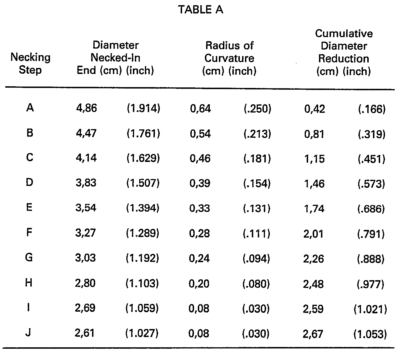
[0023] In the embodiment of the invention illustrated in Figure 2, a tubular member having
an initial diameter of 5,28cm (2,08 inches) and a wall thickness of 0,21 mm (.0083
inch) is progressively necked-in over a series of 10 necking steps to a diameter of
2,61 cm (1.027 inches). That is, a 50.6% reduction in the diameter of the tubular
member is effected by reducing the diameter approximately 7 to 8% during the initial
necking steps and approximately 3 to 4% in the final two steps. The diameter of the
necked-in portion, the radius of curvature between the dome-shaped surface and the
cylindrical necked-in portion and the cumulative diameter reduction with each necking
step are illustrated in Table A.
t
[0024] Thus, the method of making a necked-in tubular member according to the invention
comprises the steps of arranging the tubular member about a mandrel having a free
end portion with a dome-shaped surface, reducing the diameter of a free end portion
of the tubular member and forming an intermediate portion between the reduced diameter
free end portion and the remainder of the tubular member which extends along a portion
of the dome-shaped surface of the mandrel, and further reducing the diameter of the
free end portion of the tubular member and increasing the extent of the intermediate
portion along the dome-shaped surface of the mandrel. The step of further reducing
the diameter of the free end portion of the tubular member and increasing the step
of the intermediate portion along the dome-shaped surface of the mandrel is repeated
until the diameter of the free end is at least approximately 15% less than the initial
diameter. In the illustrated example, the welded tubular member is necked-in to a
diameter on the order of one-half of the original tube diameter. In another case,
a tubular member having an initial diameter of 4,45cm (1 12/16ths inch) can be necked-in
to approximately 1 inch to accept a standard aerosol valve assembly. The reduction
in this last mentioned example is approximately 40%.
[0025] The reduced free end portion of the tubular member is then trimmed to obtain a smooth
working surface as illustrated in Figure 4b. The trimmed end is thereafter curved
to form a standard size aerosol can opening upon which a conventional aerosol valve
assembly can be mounted. The free end may be curled outside in a conventional way
or, as illustrated in Figure 4d, it may be curled inside with the trimmed edge tucked
inside the curl to protect the raw edge created by trimming from aggressive products,
if any, that the container might hold. As a preliminary step in the curling operation,
a rotary operating tool is used to bead the neck inwardly at 29 to prepare and determine
the flow direction of the material in the curling step. The beaded neck is then rolled
inwardly and collapsed by way of a rotating curling tool or a punch-like curling tool
to form a standard size aerosol can opening as illustrated in Figure 4d.
[0026] While I have shown and described several embodiments in accordance with the invention,
it is understood that the same is not limited thereto, but is susceptible of numerous
changes and modifications as would be known to those skilled in the art, given the
present disclosure. For example, the upper portion of the necked container need not
be curled, but could be threaded, for example, to receive a threaded container closure.
Further, the sheet material of the tubular member need not be steel, but could be
another metal, such as aluminum or even a non-metallic material. Also while the method
and apparatus for necking-in tubular members have been described for making a dome-shaped
necked-in portion with a smooth curvilinear surface, other dome-shaped configurations
could be produced, such as conical etc. We, therefore, do not wish to be limited to
the details shown and described herein, but intend to cover all such changes and modifications
as are encompassed by the scope of the appended claims.
[0027] The described inventive method and apparatus results in relatively low cost necked-in
containers due to the fact that the container remains on a single mandrel throughout
the necking-in steps. This further leads to the possibility to neck-in the containers
in a dome-shaped configuration which is smoothly bent instead of having a series of
steps or having a wrinkled appearance.
[0028] The diameter of the free end portion of the tubular member is reduced approximately
7% to 8% in each of the initial reducing steps and 3% to 4% in the final steps to
reach a final diameter which is on the order of one half of the original diameter.
[0029] The proposed necking-in method overcomes the necessity to radially float the pressing
tools for treating containers. It is evident that this method is particularly suited
for necking-in tubular members which have a weld seam which is of essentially the
same thickness as the wall thickness of the can body outside the weld area and with
only a minimum welding-heat affected zone with minimal degradation of base material
properties. Such tubular members result from butt-welding can bodies with a high energy
density welding process, such as by laser welding or electrone beam welding, wherein
the energy density is at least 1,5 x 10
5 per square centimeter (10
6 per square inch).
1. A method of forming a neck on a tubular member whereby said tubular member is applied
to a mandrel set having a dome-shaped pressing surface set, whereby the diameter of
a free end portion of the tubular member is reduced and there is formed, along said
pressing surface set, an intermediate portion of said member between said reduced
diameter free end portion and the remainder of the member, the area of dome-shaped
pressing surface set of the mandrel set available for cooperation with the tubular
member is then at least once enlarged and the diameter of said free end portion is
at least once further reduced so that said intermediate portion along said enlarged
pressing surface of said set is at least once increased, characterized by providing
said surface set consisting of one pressing surface, and said mandrel set consisting
of one mandrel and by forming and at least once increasing said intermediate portion
(4) along said one dome-shaped surface (10) at a free end portion of said one mandrel
(9).
2. The method according to claim 1 characterized by leading said free end portion
of said member (2) into an annular gap of reduced and further reduced diameter with
respect to the diameter of said remainder of the member, to reduce and further reduce
said diameter of said free end portion.
3. The method according to claim 2 characterized by first arranging the inner wall
of said gap within said free end portion and then driving the outer wall of said gap
(16) along the outer wall of said free end portion, radially urging said free end
portion towards said inner wall of said gap.
4. The method according to one of the claims 1 to 3 characterized by reducing and
further reducing said diameter of said free end portion by at least 15% of the diameter
of said remainder of said member.
5. The method according to one of the claims 1 to 4 characterized by reducing and
further reducing said diameter of said free end portion to approximately one half
of the diameter of said remainder of said member.
6. The method according to one of the claims 1 to 5 characterized by trimming said
free end of further reduced diameter and curling it.
7. The method according to claim 6 characterized by beading said free end of further
reduced diameter inwardly and then curling it inwardly on itself so that the trimmed
edge thereof is tucked inside the curl (5).
8. The method according to one of the claims 1 to 7 characterized by reducing the
diameter of the free end portion of said tubular member with respect to the diameter
of said remainder of said member by approximately 8% by said reducing and by approximately
3% by said further reducing.
9. An apparatus for progressively necking-in an end portion of a tubular member by
a method according to claim 1, said apparatus comprising a first inside tool (9) of
a first diameter, a free end portion of said inside tool having a dome-shaped surface
(10), a plurality of second inside tools (12) each having a second diameter which
is less than the first diameter of said first inside tool (9) and having a free end
portion (13) for positioning adjacent said dome-shaped surface (10) of said first
inside tool (9) with said dome-shaped surface (10) extending between said first diameter
of said first inside tool (9) and said second diameter of said second inside tool
(12), the second diameter of said second inside tools (12) progressively decreasing
so that the extent of said dome-shaped surface (10) between said first and second
diameter progressively increases, and a plurality of outside tools (16) cooperable
with said first inside tool (9) and respective ones of said second inside tools (12).
10. An apparatus according to claim 9, wherein each of said plurality of outside tools
(16) has an internal configuration with a first portion cooperable with the first
diameter of said first inside tool (9), a second portion (18) cooperable with said
dome-shaped surface (10) extending between said first and second diameters, and a
third portion cooperable with the second diameter of one of said second inside tools
(12).
11. An apparatus according to claim 9 or 10, wherein the second diameter of said second
inside tools (12) progressively decreases to a diameter on the order of one-half of
said first diameter.
12. An apparatus according to one of claims 9 to 11, wherein means (20, 22, 28) are
provided for moving said first inside tool (9) and a cooperable pair of a second inside
tool (12) and an outside tool (16) with respect to one another for effecting necking-in
of the end portion of the tubular member.
13. An apparatus according to claim 12, wherein means (20, 21, 22, 23) are provided
for mounting said second inside tool (12) of said cooperable pair (12, 16) in a leading
and relatively movable position with respect to said outside tool (16) so that, with
relative movement of said cooperable pair (12,16) with respect to said first inside
tool (9), the second inside tool (12) reaches a position adjacent the dome-shaped
surface (10) of the first inside tool (9), while the outside tool (16) continues to
move with respect to both said first (9) and second (12) inside tools for effecting
necking-in of the end portion of the tubular member.
14. An apparatus according to claim 13, wherein said means (20, 21, 22, 23) for mounting
said second inside tool (12) of said cooperable pair (12,16) in a leading and relatively
movable position with respect to said outside tool (16) includes a spring (23) for
yieldably biasing said second inside tool (12) in said leading position.
15. An apparatus according to one of the claims 12 to 14, wherein said means (20,
22, 28) for moving comprises a press ram (20) which moves said cooperable pair (12,
16) with respect to said first inside tool (9) in a direction along the longitudinal
axis of a tubular member to be necked-in which is located about said first inside
tool (9).
16. An apparatus according to one of the claims 12 to 15, wherein said second inside
tool (12) of said cooperable pair (12, 16) includes an abutment member (24) located
centrally in its free end portion for contacting a portion of said first inside tool
(9) when said second inside tool (12) is positioned adjacent said dome-shaped surface
(10).
17. An apparatus according to claim 16, wherein a recess (25) is provided in the center
of the free end portion of said first inside tool (9) for receiving said abutment
member (24) when said second inside tool (12) is positioned adjacent said done-shaped
surface (10).
18. An apparatus according to claim 17, wherein said first inside tool (9) includes
a spacer (26) located in said recess (25) for contacting said abutment member (24)
to control the relative positions of said first (9) and second (12) inside tools.
19. An apparatus according to one of the claims 9 to 18, wherein said dome-shaped
surface (10) of the first inside tool (9) is a smooth, curvilinear surface.
20. The method according to one of the claims 1 to 8 for making a necked tubular member
of lengthwise butt-welded sheet material.
21. The method according to claim 20, characterized by said sheet material being steel
sheet material.
22. The method according to claim 21, characterized by said butt-welded sheet material
being laser welded.
1. Verfahren zur Bildung eines Halses an einem rohrförmigen Werkstück, wobei besagtes
rohrförmiges Werkstück auf einen Satz von Formdornen mit einem Satz domförmig geformter
Pressoberflächen geführt wird, und wobei der Durchmesser eines freien Endabschnittes
des rohrförmigen Werkstückes reduziert wird und entlang besagten Pressoberflächensatzes
ein Zwischenabschnitt besagten Werkstückes geformt wird, zwischen besagtem Endabschnitt
reduzierten Durchmessers und dem verbleibenden Teil des Werkstückes, wobei darnach
der Bereich des Satzes domförmig geformter Pressoberflächen des Dornsatzes, der für
die Einwirkung auf das rohrförmige Werkstück eingesetzt wird, mindestens einmal vergrössertwird,
und der Durchmesser besagten freien Endabschnittes mindestens einmal weiter reduziert
wird, so dass besagter Zwischenabschnitt entlang besagter vergrösserten Pressoberfläche
besagten Satzes mindestens einmal vergrössert wird, gekennzeichnet durch das Ausbilden
besagten Oberflächensatzes aus lediglich einer Pressoberfläche und durch das Ausbilden
besagten Dornensatzes als lediglich einen Dorn umfassend und durch das Formen und
das mindestens einmalige Vergrössern besagten Zwischenabschnittes (4) entlang besagter
einen domförmigen Oberfläche (10) an einem freien Endabschnitt des besagten einen
Dornes (9).
2. Verfahren nach Anspruch 1, gekennzeichnet durch das Einführen besagten freien Endabschnittes
besagten Werkstückes (2) in einen Ringspalt von reduziertem und weiter reduziertem
Durchmesser mit Bezug auf den Durchmesser des besagten verbleibenden Teils des Werkstückes,
um den Durchmesser besagten freien Endabschnittes zu reduzieren und weiter zu reduzieren.
3. Verfahren nach Anspruch 2, dadurch gekennzeichnet, dass zuerst die Innenwandung
besagten Spaltes in den freien Endabschnitt eingeführt wird und dann die Aussenwandung
besagten Spaltes (16) entlang der Aussenseite besagten freien Endabschnittes getrieben
wird, den freien Endabschnitt gegen besagte Innenwandung des Spaltes treibend.
4. Verfahren nach einem der Ansprüche 1 bis 3, dadurch gekennzeichnet, dass der Durchmesser
des freien Endabschnittes um mindestens 15% des Durchmessers des verbleibenden Teils
des Werkstückes reduziert und weiter reduziert wird.
5. Verfahren nach einem der Ansprüche 1 bis 4, dadurch gekennzeichnet, dass der Durchmesser
des freien Endabschnittes auf ungefähr die Hälfte des Durchmessers des verbleibenden
Teils des Werkstückes reduziert und weiter reduziert wird.
6. Verfahren nach einem der Ansprüche 1 bis 5, dadurch gekennzeichnet, dass besagtes
freies Ende weiterreduzierten Durchmessers zurechtgeschnitten und eingerollt wird.
7. Verfahren nach Anspruch 6, dadurch gekennzeichnet, dass besagtes freies Ende weiterreduzierten
Durchmessers nach innen gebogen wird und dann über sich selbst einwärts eingerollt
wird, so dass die zurechtgeschnittene Kante in die Einrollung (5) aufgenommen wird.
8. Verfahren nach einem der Ansprüche 1 bis 7, dadurch gekennzeichnet, dass der Durchmesser
des freien Endabschnittes besagten rohrförmigen Werkstückes mit Bezug auf den Durchmesser
des verbleibenden Teils des Werkstückes um ungefähr 8% erst reduziert und darnach
um ungefähr 3% weiter reduziert wird.
9. Anlage zum fortschreitenden Einformen eines Endabschnittes eines rohrförmigen Werkstückes
nach einem Verfahren nach Anspruch 1, welche ein erstes Innenwerkzeug (9) mit einem
ersten Durchmesser aufweist, wobei ein freier Endabschnitt besagten Innenwerkzeuges
eine domförmige Fläche (10) aufweist, mit einer Mehrzahl zweiter Innenwerkzeuge (12),
wovon jedes einen zweiten Durchmesser aufweist, der kleiner ist als der erste Durchmesser
des ersten Innenwerkzeuges (9) und die einen freien Endabschnitt (13) zur benachbarten
Positionierung zu besagter domförmigen Fläche (10) besagten ersten Innenwerkzeuges
(9) aufweisen, wobei sich besagte domförmige Fläche (10) zwischen besagtem ersten
Durchmesser besagten ersten Innenwerkzeuges (9) und besagtem zweiten Durchmesser besagten
zweiten Innenwerkzeuges (12) erstreckt und der zweite Durchmesser besagten zweiten
Innenwerkzeuges (12) progressiv abnimmt, so dass die Ausdehnung besagter domförmigen
Fläche (10) zwischen besagtem ersten und zweiten Durchmesser progressiv zunimmt und
mit einer Mehrzahl von Aussenwerkzeugen (16), welche mit besagtem ersten Innenwerkzeug
(9) zusammenarbeiten sowie mit entsprechenden besagten zweiten Innenwerkzeuge (12).
10. Anlage nach Anspruch 9, wobei jedes der besagten Mehrzahl Aussenwerkzeuge (16)
eine Innenkonfiguration mit einem ersten Abschnitt umfasst, welcher mit dem ersten
Durchmesser besagten ersten Innenwerkzeuges (9) zusammenwirkt, mit einem zweiten Abschnitt
(18), welcher mit besagter domförmigen Fläche (10), die sich zwischen besagtem ersten
und zweiten Durchmesser erstreckt, zusammenwirkt und mit einem dritten Abschnitt,
der mit dem zweiten Durchmesser eines besagter zweiten Innenwerkzeuge (12) zusammenwirkt.
11. Anlage nach einem der Ansprüche 9 oder 10, wobei der zweite Durchmesser des zweiten
Innenwerkzeuges (12) progressiv abnimmt, auf einen Durchmesser in der Grössenordnung
der Hälfte des ersten Durchmessers.
12. Anlage nach einem der Ansprüche 9 bis 11, worin Organe (20, 22, 28) vorgesehen
sind, um das erste Innenwerkzeug (9) und ein zusammenwirkendes Paar eines zweiten
Innenwerkzeuges (12) und eines Aussenwerkzeuges (16) relativ zueinander zu bewegen,
um das Einformen des Endabschnittes des rohrförmigen Werkstükkes vorzunehmen.
13. Anlage nach Anspruch 12, worin Organe (20, 21, 22, 23) vorgesehen sind, um besagtes
zweite Innenwerkzeug (12) besagten zusammenwirkenden Paares (12, 16) in vorgezogene
und relativ bewegliche Position mit Bezug auf besagtes Aussenwerkzeug (16) zu montieren,
so dass durch Relativbewegung besagten zusammenwirkenden Paares (12, 16), mit Bezug
auf besagtes ersten Innenwerkzeug (9), das zweite Innenwerkzeug (12) eine der domförmigen
Fläche (10) des ersten Innenwerkzeuges (9) benachbarte Position erreicht, während
das Aussenwerkzeug (16) sich weiter bewegt, mit Bezug auf beide, besagten ersten (9)
und zweiten (12) Innenwerkzeuge, um den Einformvorgang am besagten Endabschnitt des
rohrförmigen Werkstückes zu bewirken.
14. Anlage nach Anspruch 13, worin besagte Organe (20, 21, 22, 23) um besagtes zweites
Innenwerkzeug (12) besagten zusammenwirkenden Paares (12, 16) in eine vorgezogene
und relativ bewegliche Position zu montieren, mit Bezug auf besagtes Aussenwerkzeug
(16), eine Feder (23) umfassen, um besagtes zweites Innenwerkzeug (12) federnd in
besagte vorgezogene Position zu spannen.
15. Anlage nach einem der Ansprüche 12 bis 14, worin besagte Organe (20, 22, 28) zum
Antreiben einen Presskolben (20) umfassen, welcher besagtes zusammenwirkendes Paar
(12, 16) mit Bezug auf besagtes erstes Innenwerkzeug (9) bewegt, in einer Richtung
entlang der Längsachse des rohrförmigen Werkstückes, das einzuformen ist, und welches
über dem ersten Innenwerkzeug (9) angeordnet ist.
16. Anlage nach einem der Ansprüche 12 bis 15, worin besagtes zweites Innenwerkzeug
(12) besagten zusammenwirkenden Paares (12, 16) ein Anschlagglied (24) umfasst, das
zentral in seinem freien Endabschnitt angeordnet ist, um einen Abschnitt besagten
ersten Innenwerkzeuges (9) zu kontaktieren, wenn besagtes zweites Innenwerkzeug (12)
benachbart zu besagter domförmigen Fläche (10) positioniert ist.
17. Anlage nach Anspruch 16, worin eine Einnehmung (25) vorgesehen ist, im Zentrum
des freien Endabschnittes besagten ersten Innenwerkzeuges (9), um das Anschlagorgan
(24) aufzunehmen, wenn besagtes zweite Innenwerkzeug (12) benachbart der domförmigen
Fläche (10) positioniert ist.
18. Anlage nach Anspruch 17, worin besagtes erstes Innenwerkzeug (9) einen Abstandshalter
(26) umfasst, angeordnet in besagter Einnehmung (25), um besagtes Anschlagorgan (24)
zu kontaktieren, um die Relativpositionen besagter ersten (9) und zweiten (12) Innenwerkzeuge
zu beherrschen.
19. Anlage nach einem der Ansprüche 9 bis 18, worin besagte domförmige Fläche (10)
des ersten Innenwerkzeuges (9) eine stetig gebogene Fläche ist.
20. Verfahren nach einem der Ansprüche 1 bis 8, um rohrförmige Teile längsstumpfgeschweissten
Blattmaterials einzuformen.
21. Verfahren nach Anspruch 20, dadurch gekennzeichnet, dass besagtes Blattmaterial
Stahlblattmaterial ist.
22. Verfahren nach Anspruch 21, dadurch gekennzeichnet, dass besagtes stumpfgeschweisstes
Blattmaterial lasergeschweisst ist.
1. Procédé de formation d'un col sur un organe tubulaire, selon lequel l'organe tubulaire
est appliqué sur un jeu de mandrins ayant un jeu de surfaces de compression en forme
de dôme, de manière que le diamètre, d'une partie libre d'extrémité de l'organe tubulaire
subisse un rétrécissement, et qu'une partie intermédiaire de l'organe soit formée,
le long du jeu de surfaces de compression, entre la partie d'extrémité libre de diamètre
réduit et le reste de l'organe, l'étendue du jeu de surfaces de compression en forme
de dôme du jeu de mandrins disponible pour la coopération avec l'organe tubulaire
étant agrandie au moins une fois et le diamètre de la partie d'extrémité libre étant
réduit au moins une fois supplémentaire si bien que la partie intermédiaire, le long
de la surface agrandie de compression du jeu, subit au moins une fois un agrandissement,
caractérisé en ce que le jeu de surfaces est formé d'une seule surface de compression,
et le jeu de mandrins est formé d'un seul mandrin, et par la formation et l'agrandissement
au moins une fois de la partie intermédiaire (4) le long de ladite surface en forme
de dôme (10) dans la partie d'extrémité libre du mandrin unique (9).
2. Procédé selon la revendication 1, caractérisé en ce qu'il comprend le guidage de
la partie d'extrémité libre dudit organe (2) dans un espace annulaire de diamètre
qui est réduit et réduit de façon suplémentaire par rapport au diamètre du reste de
l'organe, afin que le diamètre de la partie d'extrémité libre soit réduit et réduit
de façon supplémentaire.
3. Procédé selon la revendication 2, caractérisé par la disposition initiale de la
paroi interne dudit espace dans la partie d'extrémité libre, puis le déplacement de
la paroi externe dudit espace (16) le long de la paroi externe de la paroi externe
de la partie d'extrémité libre, afin qu'elle déplace radialement la partie d'extrémité
libre vers la paroi interne dudit espace.
4. Procédé selon l'une quelconque des revendications 1 à 3, caractérisé par la réduction
et par une réduction supplémentaire du diamètre de la partie d'extrémité libre d'au
moins 15% du diamètre du reste de l'organe.
5. Procédé selon l'une quelconque des revendications 1 à 4, caractérisé par la réduction
et la réduction supplémentaire du diamètre de la partie d'extrémité libre à la moitié
environ du diamètre du reste dudit organe.
6. Procédé selon l'une des revendications 1 à 5, caractérisé par la découpe de l'extrémité
libre de diamètre ayant subi une réduction supplémentaire et son bordage.
7. Procédé selon la revendication 6, caractérisé par le bombage de l'extrémité libre
de diamètre ayant subi une réduction supplémentaire, vers l'intérieur, puis son roulage
vers l'intérieur sur lui-même afin que le bord découpé soit plié à l'intérieur de
la partie enroulée (5).
8. Procédé selon l'une quelconque des revendications 1 à 7, caractérisé par la réduction
du diamètre de la partie d'extrémité libre de l'organe tubulaire par rapport au diamètre
du reste de l'organe d'environ 8% lors de la réduction et d'environ 3% lors de la
réduction supplémentaire.
9. Appareil de rétrécissement progressif d'une partie d'extrémité d'un organe tubulaire
par mise en oeuvre d'un procédé selon la revendication 1, l'appareil comprenant un
premier outil interne (9) d'un premier diamètre, une partie d'extrémité libre de l'outil
interne ayant une surface en forme de dôme (10), plusieurs seconds outils internes
(12) ayant chacun un second diamètre qui est inférieur au premier diamètre du premier
outil interne (9) et ayant une partie d'extrémité libre (13) destinée à être placée
près de la surface en forme de dôme (10) du premier outil interne (9), la surface
en forme de dôme (10) étant placée entre le premier diamètre du premier outil interne
(9) et le second diamètre du second outil interne (12), le second diamètre des seconds
outils internes (12) diminuant progressivement afin que l'étendue de la surface en
forme de dôme (10) comprise entre le premier et le second diamètre augmente progressivement,
et plusieurs outils externes (16) destinés à coopérer avec le premier outil interne
(9) et les seconds outils internes respectifs (12).
10. Appareil selon la revendication 9, dans lequel chacun des outils externes (16)
a une configuration interne comportant une première partie destinée à coopérer avec
le premier diamètre du premier outil interne (9), une seconde partie (18) destinée
à coopérer avec la surface en forme de dôme (10) disposée entre le premier et le second
diamètre, et une troisième partie destinée à coopérer avec le second diamètre d'un
premier des seconds outils internes (12).
11. Appareil selon la revendication 9 ou 10, dans lequel le second diamètre des seconds
outils internes (12) diminue progressivement jusqu'à un diamètre de l'ordre de la
moitié du premier diamètre.
12. Appareil selon l'une des revendications 9 à 11, dans lequel un dispositif (20,
22, 28) est destiné à déplacer le premier outil interne (9) et une paire coopérante
d'un second outil interne (12) et d'un outil externe (16) l'un par rapport à l'autre
afin qu'il assure le rétrécissement de la partie d'extrémité de l'organe tubulaire.
13. Appareil selon la revendication 12, dans lequel un dispositif (20, 21, 22, 23)
est destiné au montage du second outil interne (12) de la paire coopérante (12, 16)
en position avant afin qu'il soit mobile par rapport à l'outil externe (16) et que,
lors du déplacement de la paire coopérante (12, 16) par rapport au premier outil interne
(9), le second outil interne (12) atteigne une position adjacente à la surface en
forme de dôme (10) du premier outil interne (9), alors que l'outil externe (16) continu
à se déplacer par rapport aux premier (9) et second (12) outils internes afin qu'il
assure le rétrécissement de la partie d'extrémité de l'organe tubulaire.
14. Appareil selon la revendication 13, dans lequel le dispositif (20, 21, 22, 23)
de montage du second outil interne (12) de la paire coopérante (12,16) en position
antérieure et mobile par rapport à l'outil externe (16) comporte un ressort (23) destiné
à rappeler élastiquement le second outil interne (12) en position avant.
15. Appareil selon l'une des revendications 12 à 14, dans lequel un dispositif (20,
22, 28) de déplacement comporte un vérin (20) de presse qui déplace la paire coopérante
(12, 16) par rapport au premier outil interne (9) suivant l'axe longitudinal de l'organe
tubulaire afin que celui-ci subisse un rétrécissement lorsqu'il est placé autour du
premier outil interne (9).
16. Appareil selon l'une des revendications 12 à 15, dans lequel le second outil interne
(12) de la paire coopérante (12,16) comporte un organe de butée (24) placé au centre
dans sa première partie d'extrémité et destiné à être au contact d'une partie du premier
outil interne (9) lorsque le second outil interne (12) est placé près de la surface
en forme de dôme (10).
17. Appareil selon la revendication 16, dans lequel une cavité (25) est formée au
centre de la partie d'extrémité libre du premier outil interne (9) afin qu'elle loge
l'organe de butée (24) lorsque le second outil interne (12) est placé à proximité
de la surface en forme de dôme (10).
18. Appareil selon la revendication 17, dans lequel le premier outil interne (9) comporte
une entretoise (26) placée dans ladite cavité (25) et destinée à être au contact de
l'organe de butée (24) afin qu'il règle les positions relatives du premier (9) et
du second (12) outil interne.
19. Appareil selon l'une des revendications 9 à 18, dans lequel la surface en forme
de dôme (10) du premier outil interne (9) est une surface curviligne régulière.
20. Procédé selon l'une des revendications 1 à 8, destiné à la fabrication d'un organe
tubulaire ayant un col, constitué d'un matériau en feuille soudé bout à bout en direction
longitudinale.
21. Procédé selon la revendication 20, caractérisé en ce que le matériau en feuille
est une feuille d'acier.
22. Procédé selon la revendication 21, caractérisé en ce que le matériau en feuille
soudé bout à bout est soudé au laser.