| (19) |
 |
|
(11) |
EP 0 156 624 B1 |
| (12) |
EUROPEAN PATENT SPECIFICATION |
| (45) |
Mention of the grant of the patent: |
|
28.02.1990 Bulletin 1990/09 |
| (22) |
Date of filing: 20.03.1985 |
|
| (51) |
International Patent Classification (IPC)5: G02C 7/02 |
|
| (54) |
Lens tinting fixture and system utilizing said fixture
Haltevorrichtung zum Einfärben von Linsen und Verwendung dieser Haltevorrichtung
Support pour teindre des lentilles et système utilisant ce support
|
| (84) |
Designated Contracting States: |
|
AT BE CH DE FR GB IT LI LU NL SE |
| (30) |
Priority: |
23.03.1984 US 592694
|
| (43) |
Date of publication of application: |
|
02.10.1985 Bulletin 1985/40 |
| (73) |
Proprietor: ALLERGAN, INC |
|
Irvine, California 92715 (US) |
|
| (72) |
Inventors: |
|
- Rabenau, Richard
Arab
Alabama 35016 (US)
- Ryder, Jeffery Allen
Arab
Alabama 35016 (US)
|
| (74) |
Representative: Carpenter, David et al |
|
MARKS & CLERK,
Alpha Tower,
Suffolk Street Queensway
Birmingham B1 1TT
Birmingham B1 1TT (GB) |
| (56) |
References cited: :
DE-A- 3 219 890
GB-A- 1 004 424
US-A- 3 046 668
|
FR-A- 2 355 642
GB-A- 2 130 507
|
|
| |
|
|
|
|
| |
|
| Note: Within nine months from the publication of the mention of the grant of the European
patent, any person may give notice to the European Patent Office of opposition to
the European patent
granted. Notice of opposition shall be filed in a written reasoned statement. It shall
not be deemed to
have been filed until the opposition fee has been paid. (Art. 99(1) European Patent
Convention).
|
[0001] This invention relates generally to the tinting or coloration of contact lenses for
human eyes.
[0002] For some time now, it has been possible to correct or improve the vision of the human
eye by disposing a small, transparent lens directly upon the surface of the eyeball.
The contours of this contact lens supplement and correct the effects of the biological
lens within the eyeball.
[0003] Early contact lenses were primarily of the "hard" variety. More recently, however,
so-called "soft" contact lenses have been introduced, and these lenses have met with
considerable popularity. "Soft" contact lenses are manufactured from a hydrophyllic
plastic material; that is, they can absorb and retain water, and become soft and pliable
upon the absorbtion of water. They are relatively comfortable for the user to wear,
and can be worn for relatively long periods of time.
[0004] Tinted or colored "soft" contact lenses have advantages or attractions to a variety
of contact lens users.
[0005] Tinted lenses provide cosmetic improvement for persons having one, or both, eyes
which have been disfigured by illness or accident. Tinted lenses can be used by patients
with diplopia to make them appear more normal. Also tinted lenses may provide albino
and aniridic patients with improved general facial appearances. Suitably tinted lenses
can also reduce light transmission and give the patient increased visual comfort.
[0006] Several methods of coloring central areas of contact lenses are suggested in U.S.
patent 4,252,421 to Foley, Jr. However, the tinting or coloration of contact lenses
is not a simple task. If colors are printed on transparent lenses, the coloration
may not be uniformly dispersed through the lens material. Moreover, the color printed
upon such lenses tends to fade after several cleanings or autoclavings.
[0007] It is important that the tinted or colored lens provide a natural appearance in the
wearer's eye, of course. Thus, a natural-appearing soft contact lens should have a
clear central area, a colored intermediate area and a clear outer area so that the
colored portion will not cover the sclera of the eye. Moreover, the central portion
of the lens should be uncolored to permit maximum light passage into the eye interior.
Thus, it is desirable to be able to provide the lens with a ring-like annular tinted
area, surrounded by clear, untinted lens material.
[0008] In manufacturing single-part tinted lenses, several problems can arise in mounting
a lens on a tinting fixture. It is important that the worker not handle the lens directly
with his or her fingers or fingertips, because the minute amounts of oil contained
on the worker's fingertips will prevent the dye from being accepted or absorbed evenly
by the lens. If the worker uses gloves, dexterity can be reduced. This dexterity is
important in manipulating the small lenses and centering the lens on the tinting fixture.
If the worker uses tweezers and manually mounts the lens on a fixture, lens production
can be slow, and accuracy in the mounting may be compromised.
[0009] As suggested above, it is important that the tinted annular area of the lens, and
correspondingly the clear central portion be precisely defined and accurately located.
That is, even slight fuzziness or running of dye colors into otherwise uncolored areas
of the lens will be immediately apparent. Fuzziness or tint runs will necessitate
the rejection of the finished lens product.
[0010] It is an object of this invention to provide an improvement in the tinting of contact
lenses or the like.
[0011] According to one aspect of this invention there is provided an apparatus for tinting
a contact lens or the like, the apparatus being provided with a tubular component
having a tube body portion and an end portion, the tube body being capable of at least
temporarily retaining a quantity of fluid and receiving a contact lens dropped into
the fluid, the end portion including mask structure adapted to engage and support
the lens and mask certain portions thereof, said mask structure including two coaxial,
seat portions spaced apart from one another to define an annular, unmasked tintable
area on the contact lens and, a mandrel member being provided for engaging a concave
side of the lens and securely urging a convex side of the lens against said mask structure,
openings being provided near the end portion of said tube body portion to allow tinting
medium to be fed into a tinting chamber for contacting the unmasked portions of the
lens.
[0012] According to another aspect of this invention there is provided a method of tinting
a contact lens characterized by the steps of providing a tube-like structure which
is closed at one end by a mask structure and which is open at the other end; orienting
the tube like structure in a first position with the open end upward; adding a fluid
to the interior of said tube structure; dropping the lens to be tinted into the fluid
permitting the lens to sink through the fluid column, so as to cause the lens to orient
and center itself relative to the tube structure; permitting the oriented centered
lens to come to rest on the mask structure; inserting a mandrel member into the tube-like
structure to secure the lens in place relative to the mask structure; draining the
fluid from said tube-like structure; and applying a dye tinting medium to unmasked
portions of the secured and masked lens.
[0013] This invention will now be described in more detail by way of example with reference
to the drawings in which
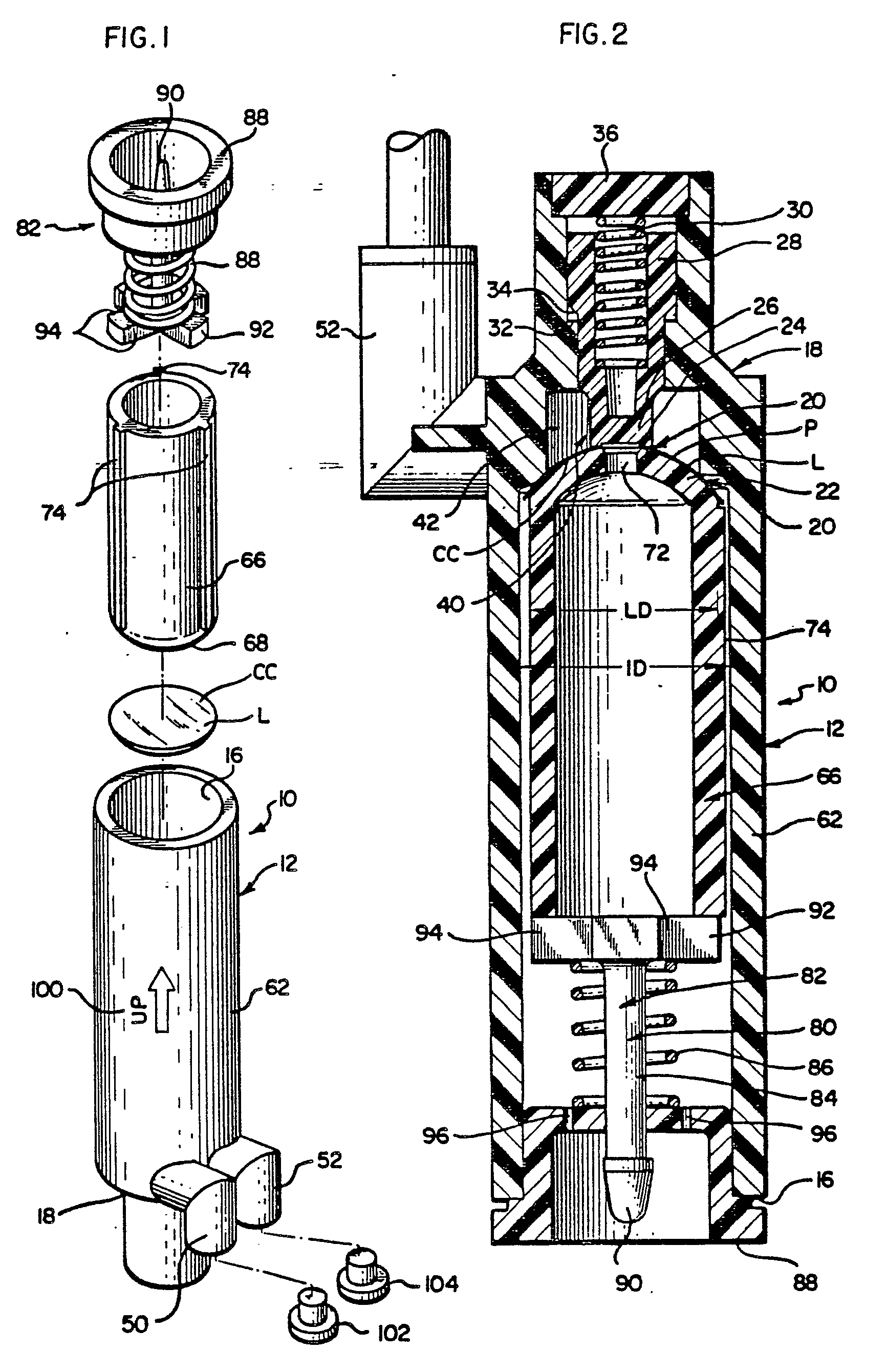
Figure 1 is an exploded view of the apparatus comprising the invention;
Figure 2 is a sectional view showing the apparatus of Fig 1 in its assembled condition
and inverted;
Figure 3 is a fragmentary sectional view showing in further detail the masking portion
of the fixture in a position as per Fig. 1, and inverted from that shown in Fig 2;
Figure 4 is a fragmentary sectional view taken substantially in the plane of line
4-4 in Fig 3;
Figure 5 is a sectional view taken substantially in the planes of lines 5-5 in Fig
4;
Figure 6 is a fragmentary sectional view showing the motion of a contact lens as its
passes through a column of fluid contained within a tube portion of the novel fixture;
and
Figure 7 is a fragmentary sectional view similar to Fig 6 and showing action of the
fluid as a mandrel member is inserted into the tube.
[0014] While the invention will be described in connection with a preferred embodiment and
procedure, it will be understood that it is not intended to limit the invention to
this embodiment or procedure. On the contrary, it is intended that the invention cover
all alternatives, modifications and equivalents as may be included within the scope
of the invention as defined by the appended claims.
[0015] Turning first to Figs 1 and 2, there is shown a preferred embodiment of the fixture
or apparatus 10 comprising the invention. In general, the fixture of apparatus 10
can be considered to include a elongate tube 12 into which a contact lens L can be
dropped or otherwise inserted. One end 16 of this tube 12 is generally open, while
the other end 18 is closed by specially designed masking structure.
[0016] The tube-closing structure 18 includes a lens mask structure 20. Here this mask structure
includes an outer, annular seat or mask portion 22; and spaced apart therefrom but
coaxial therewith, an inner seat or mask portion 24. To provide desired resiliency
in supporting, engaging, and masking portions of the contact lens L, this inner seat
or mask 24 is formed on the nose 26 of a plunger 28 which is biased, as by a spring
30, toward the lens L. Thus, the spring biasing means 30 urges the inner mask seat
24 toward the lens L and into firm contact therewith. Plunger motion toward the lens
L is halted or restrained by a shoulder 32 formed on the bottom portion of the tube
12; a mating shoulder 34 is formed on the plunger 28. The spring 30 and plunger 28
are retained within the tube structure 12 by any convenient device such as a cap or
plug 36.
[0017] A chamber means 40 is provided at the closed end of the tube 12 proximate the mask
structure 20 for providing tinting medium to the unmasked portions P of the lens L.
Here, this chamber 40 includes a cylindrical cavity 42 surrounding the plunger nose
26 and inner mask seat 24, and disposed inwardly of the outer mask portion 22.
[0018] To admit a fluid tinting medium or dye solution to the chamber cavity 42, inlet and
outlet ports 50, 52 are provided, as shown in FIGS. 2, 4 and 5. Tinting medium is
encouraged to swirl through the chamber 40 and past the lens L by orienting the inlet
and outlet ports 50, 52 substantially tangential to a wall 54 of the cylindrical cavity
42. To encourage the removal of bubbles of air and the accumulation of any preliminary
solution squeezed out of the lens during lens capture, the inlet port 50 is smaller
than the outlet port 52, and the inlet port 50 is located tangentially as noted above,
and also at an axially upper position, relative to the outlet port 52.
[0019] The tube 12 includes an elongate body portion 62 capable of retaining a column of
fluid. The diameter of this body portion 62 is just slightly greater than the diameter
of the lens L Preferably, the internal diameter ID of the tube body portion 62 is
approximately 2mm. larger than the lens diameter LD. The height of the column of fluid
and the height of the body portion 62 is from one to three times the diameter of the
lens LD, and preferably two and one half times the lens diameter LD. When the lens
L is then dropped into the fluid-filled tube 12, the contact lens descends through
the fluid and attains a state of dynamic equilibrium, with a lens convex side CV down,
as suggested in Fig 6. As the lens falls downwardly through the column of fluid, the
hydraulic forces acting on the lens will operate to centre the lens with respect of
the tube. Thus the lens will be in both the desired orientation and properly centered
when it engages the mask means 20.
[0020] To engage the lens L and secure the lens L against the mask means or structure 20
in a position to be contacted by the tinting medium, mandrel 66 is inserted into the
tube 62 as suggested in Figs 2 and 7. This mandrel 66 is provided with a rounded nose
portion 68 adapted to engage the concave side CC of the lens L.
[0021] So that the column of fluid will not overflow the open top 16 of the tube 12, the
mandrel 66 is hollow, and a port or hole 72 is formed in the mandrel nose 68 to permit
the fluid to flow into the mandrel interior, as illustrated in FIG. 7. This permits
the mandrel 66 to sink into the fluid in the tube means with a controlled motion;
the mandrel being centered by the hydraulic forces in the same manner as was the lens
L. In addition, external spacer ribs 74 are formed on the outside of the mandrel 66
so as to space the mandrel 66 from the tube body wall and permit the fluid to flow
between the mandrel 66 and tube body wall to further enhance the centering action.
[0022] When the mandrel 66 has been fully inserted into the tube 12, a mandrel lock mechanism
80 is inserted into the tube 12 to force the mandrel 66 against the lens L and force
the lens L against the mask structure 20. As illustrated in FIGS. 2, 3 and 4, this
locking mechanism 80 takes the form of a plunger 82 which is provided with a stem
84 surrounded by a compression spring 86. A lock cap 88, which can conveniently be
of the plug type, is secured to the plunger stem 84; here, the plunger stem 84 is
provided with an enlarged nose 90 to prevent loss of the cap 88 from the stem 84.
[0023] It will be noted that the plunger 82 is provided with an enlarged base 92, but this
base 92 is provided with several cut-away formations 94. Further, the cap 88 is provided
with several drain holes 96. Thus, when the assembled tube and mandrel arrangement
is inverted from the initial or assembly position shown in FIG. 1 to the operating
position shown in FIG. 2, the column of fluid drains out of the tube.
Method of Using the Lens Tinting Fixture
[0024] Using the fixture of the present invention to produce a tinted contact lens is not
difficult, and can be accomplished by even inexperienced personnel quickly and easily
and at a minimal cost, and requires no special skills or manual dexterity.
[0025] First, the tube assembly shown in Fig 1 is located in a rack or holder, not shown,
in the assembly position as shown in Figs 1, 6 and 7. Port plugs 102, 104 are inserted
in the respective inlet and outlet ports 50, 52 to prevent loss of fluid. Next, the
tube is filled to an appropriate height with receiving or preparatory fluid that insures
that the lens will be maintained in a sterile and dydrophilic condition. This fluid
may be suitably tinted water.
[0026] Next, the lens to be tinted is picked up by tweezers or some other clean device,
and is deposited into the fluid and allowed to sink freely toward the closed end of
the tube assembly 12. As it drops, the lens will orient and centre itself as suggested
in Fig 6, and will finally come to rest on the mask structure 20, as shown in Figs
6 and 7, not only with the convex side down, but properly centered relative to the
mask structure 20.
[0027] Thereafter, the mandrel 66 is dropped into the tube 12, as suggested in Fig 7. The
mandrel will also center itself, and the mandrel nose 68 will engage the concave side
CC of the lens L. Fluid flows into the interior portion of the mandrel 66 through
the port 72, as explained previously, so as to permit the mandrel 66 to sink into
the lense- engaging position and to avoid fluid overflow and spillage.
[0028] The mandrel locking assembly 82 is thereafter inserted into the open top 16 of the
tube 12. By this action, the mandrel 66 is pressed into firm engagement with the lens
L, and the lens L is pressed into firm engagement with both the outer mask 22 and
the inner mask 24 of the masking structure 20. It will be recalled that the inner
mask 24 can be displaced slightly by this mandrel forcing action against the action
of the plunger biasing spring 30.
[0029] The completely assembled device, with the captured lens, is now visually checked
to be sure that the lens L has been properly seated. To this end, the tube 12 and
other parts of the assembly are preferably formed of transparent plastic or other
suitable materials. However, the mandrel 66 formed of opaque plastic, so as to enable
the operator to better see the lens L. If the lens has not been properly located and
seated, the mandrel locking mechanism 82 and mandrel 66 are removed, and the lens
is then removed. The lens is then re-dropped, and the mechanism is reassembled.
[0030] If the lens has been properly captured and secured, the plugs 102 and 104 are removed
to drain the preparatory fluid from the tinting chamber 40. Next the entire assembly
or fixture is inverted into the position shown in FIG. 2. As explained above, this
inversion motion permits the fluid column on the side of the lens opposite the tinting
chamber 40 to be drained from the assembled fixture.
[0031] In a preferred method of lens tinting, the entire fixture and lens may then be heated
prior to introduction of the tinting agent or medium. When the fixture and lens have
reached a steady elevated temperature, a dye solution or tinting medium is introduced
into the tinting chamber 40 through the inlet port 50. Because of the size and location
of the inlet port 50 and outlet port 52 described above, the tinting medium enters
the tinting chamber 40 tangentially to the walls thereof with a low pressure swirling
action. This fluid swirling action ensures an even application of the tinting medium
to the unmasked area of the lens. Also this action causes any bubbles of air to be
removed from the convex surface CV of the lens L, which constitutes the temporary
bottom surface of the tinting chamber 12. These air bubbles are then swept out through
the outlet port. Removal of air bubbles in this way is highly desirable, because the
presence of bubbles on the surface of the lens L can cause voids or irregularities
in the finished tint.
[0032] It will also be noted that any preparatory solution on the lens L which has been
squeezed out of the lens by the locking or securing action of the mandrel 66, will
also be swept out of the tinting chamber 42. If this solution were allowed to accumulate
in the tinting chamber, the tint medium might be diluted and an uneven tinting action
might result.
[0033] After an appropriate period of tinting time, the tinting medium or dye solution is
flushed out of the chamber by an injection of distilled water. Next, a fixing agent
is introduced into the tinting chamber 40 to oxidize or fix the dye deposited upon
and in the lens L. After the fixing agent has contacted the lens, another rinsing
or flushing injection of distilled water is introduced to remove residual fixer. Thereafter,
a final rinse is circulated through the chamber 40 to neutralize any residual acids
and insures that the tinted lens is returned to an acceptable pH level.
[0034] Finally, the mandrel lock assembly 82 is removed, and the mandrel 66 is removed.
The lens is now removed from the fixture 10 and given a final inspection before passage
to packaging, transport and sale.
[0035] There has been disclosed a preferred construction and method of use for the fixture
10 of the present invention. It is anticipated that those skilled in the art may devise
various alternatives or modifications to the disclosed embodiment, once possessed
of the present disclosure. As such this disclosure is not intended to limit the invention,
but rather to illustrate a preferred embodiment, the scope of the invention being
defined by the claims appended hereto.
1. Apparatus for tinting a contact lens or the like, the apparatus characterized in
that there is provided tubular component (12) having a tube body portion (62) and
an end portion (18), the tube body (62) being capable of at least temporarily retaining
a quantity of fluid and receiving a contact lens (L) dropped into the fluid, the end
portion (18) including a mask structure (20) adapted to engage and support the lens
(L) and mask certain portions thereof, said mask structure (20) including two coaxial,
seat portions (22, 24) spaced apart from one another to define an annular, unmasked
tintable area (P) on the contact lens (L) and, a mandrel member (66) being provided
for engaging a concave side (CC) of the lens (L) and securely urging a convex side
(CV) of the lens (L) against said mask structure (20), openings (50, 52) being provided
near the end portion (18) of said tube body portion (62) to allow tinting medium to
be fed into a tinting chamber (40) for contacting the unmasked portions of the lens
(L).
2. Apparatus according to claim 1 characterized in that there is provided a mandrel
lock mechanism (80) for resiliently locking the mandrel (66) in its lens-engaging
position;
3. Apparatus according to claim 1 or claim 2 characterized in that a drain system
(96) is provided for permitting the fluid to be drained from said tube body portion
(62).
4. Apparatus according to any one of claims 1 to 3, characterized in that one of said
seat portions is an inner seat (24), and there is provided biasing structure (30)
for urging the inner seat (24) toward the lens (L) and into firm contact therewith.
5. Apparatus according to claim 1 characterized in that a mandrel member (66) is provided
with a nose portion (68) for engaging the concaved side (CC) of the lens (L), and
wherein said mask structure includes at least one seat portion (22 or 24) for engaging
at least part of an opposite, convexed side (CV) of the lens (L).
6. Apparatus according to claim 1 wherein the structure for providing tinting medium
to the unmasked portions of the lens is characterized by a chamber (40) including
a cylindrical cavity (42), and inlet and outlet ports (50 and 52) oriented substantially
tangential to the cylindrical cavity (42), whereby to encourage the tinting medium
to swirl through said chamber (40) and into contact with the lens (L).
7. Apparatus according to claim 6 wherein said mask structure (20) is characterized
by an inner seat (22) and an outer seat (24), and wherein said chamber (40) surrounds
the inner seat (22).
8. Apparatus according to claim 6 characterized in that said inlet port (50) is located
at an upper location, and wherein said outlet port (52) is located at a lower location,
whereby to encourage a complete and even sweeping-action passage of tinting medium
past said lens (L) and consequent complete and even tinting of said lens.
9. Apparatus according to claim 1 characterized in that said tube body portion (62)
is at least as long as the diameter of the lens.
10. Apparatus according to claim 1 characterized in that said tube body portion (62)
is no more than three times as long as the diameter of the lens (L).
11. Apparatus according to claim 1 characterized in that said tube body portion (62)
is substantially two and one-half times as long as the diameter of the lens (L).
12. Apparatus according to any of claims 1-8 characterized in that said tube body
portion (62) has a length sufficient to support a fluid column having a height which
will permit a contact lens (L) dropped there into to attain a state of dynamic equilibrium,
with a lens convex side (CV) down, as the lens (L) falls downwardly through the column
of fluid.
13. Apparatus according to any of claims 1-8 characterized in that said tube body
portion (62) has a diameter (ID) only slightly larger than that of the contact lens
(L), and has a length such that when said tube body portion (62) is filled with a
column of liquid and a lens (L) is deposited therein, said lens (L) will fall through
the column of liquid with the hydraulic forces acting thereon producing a state of
dynamic equilibrium, with the lens convex side (CV) down, thereby tending to position
and center the lens (L) properly relative to said tube body portion (62), so that
the lens (L) will be deposited upon said mask structure (20) in centered relationship
and with the convex side (CV) thereof engaging said mask structure (20).
14. A method of tinting a contact lens characterized by the steps of: providing a
tube-like structure (12) which is closed at one end by mask structure (20) and which
is open at the other end; orienting the tube-like structure (12) in a first position
(Fig. 6) with the open end upward; adding a fluid to the interior of said tube structure
(12); dropping the lens (L) to be tinted into the fluid; permitting the lens (L) to
sink through the fluid column, so as to cause the lens to orient and center itself
relative to the tube structure (12); permitting the oriented and centered lens (L)
to come to rest on the mask structure (20), (Fig. 6); inserting a mandrel member (66)
into the tube-like structure (12) to secure the lens (L) in place relative to the
mask structure (20); draining the fluid from said tube-like structure (12); and applying
a dye tinting medium to unmasked portions of the secured and masked lens.
15. A method according to claim 14 characterized in that the step of draining the
fluid includes the step of inverting the tube-like structure (12). (Fig. 2).
16. A method according to claim 14 or claim 15 further characterized by the steps
of removing said tinting medium, and thereafter applying a fixing medium to said tinted
lens (L) to fix said tint to and in said lens.
17. A method according to claim 16 further characterized by the step of flushing said
lens after applying said fixing medium to said lens.
1. Vorrichtung zur Abtönung einer Kontaktlinse oder dergleichen, dadurch gekennzeichnet,
daß ein röhrenförmiger Teil (12) mit einem Rohrkörperabschnitt (62) und einem Endabschnitt
(18) vorgesehen ist, wobei der Rohrkörper (62) befähigt ist, zumindest zeitweise eine
Menge eines Mediums zurückzuhalten und eine in das Medium fallengelassene Kontaktlinse
(L) aufzunehmen, wobei der Endabschnitt (18) eine Maskierungsstruktur (20) einschließt,
die befähigt ist, sich an die Linse (L) anzulegen und diese abzustützen, um hierdurch
bestimmte Linsenteile abzudecken, und wobei die Maskierungsstruktur (20) zwei koaxiale,
voneinander räumlich getrennte Auflageteile (22, 24) einschließt, die auf der Kontaktlinse
(L) einen ringförmigen, unmaskierten, abtönbaren Bereich (P) bestimmen, und daß ein
Spanndornglied (66) vorgesehen ist, das an einer konkaven Seite (CC) der Linse (L)
angreift und eine konvexe Seite (CV) der Linse (L) sicher gegen die Maskierungsstruktur
(20) andrückt, wobei nahe dem Endabschnitt (18) des Rohrkörperabschnitts (62) Öffnungen
(50, 52) vorgesehen sind, welche die Einspeisung eines Abtönmediums in eine Abtönkammer
(40) gestatten, so daß die unmaskierten Teile der Linse (40) damit in Kontakt gelangen.
2. Vorrichtung nach Anspruch 1, dadurch gekennzeichnet, daß ein Spanndornfeststellmechanismus
(80) vorgesehen ist, mit dem der Spanndorn (66) in seiner an der Linse angreifenden
Position elastisch feststellbar ist.
3. Vorrichtung nach Anspruch 1 oder 2, dadurch gekennzeichnet, daß ein Entleerungssystem
(96) vorgesehen ist, das eine Entleerung des Mediums aus dem Rohrkörperabschnitt (62)
gestattet.
4. Vorrichtung nach einem der Ansprüche 1 bis 3, dadurch gekennzeichnet, daß einer
der Auflageteile eine innere Auflage (24) ist und ein Vorspannaufbau (30) vorgesehen
ist, um die innere Auflage (24) zur Linse (L) hin und in festen Kontakt damit zu drücken.
5. Vorrichtung nach Anspruch 1, dadurch gekennzeichnet, da8 ein Spanndornglied (66)
mit einem Nasenabschnitt (68) versehen ist, der an der konkaven Seite (CC) der Linse
(L) anliegt, und daß die Maskierungsstruktur wenigstens einen Auflageteil (22 oder
24) einschließt, der an wenigstens einem Teil einer gegenüberliegenden, konvexen Seite
(CV) der Linse (L) anliegt.
6. Vorrichtung nach Anspruch 1, bei welcher die Struktur zur Versorgung der unmaskierten
Teile der Linse mit Abtönmedium durch eine Kammer (40) gekennzeichnet ist, die einen
zylindrischen Hohlraum (42) sowie Ein- und Auslaßöffnungen (50 und 52) einschließt,
wobei diese Öffnungen (50, 52) im wesentlichen tangential zum zylindrischen Hohlraum
(42) orientiert sind, so daß das Abtönmedium veranlaßt ist, durch die Kammer (40)
und in Kontakt mit der Linse (L) zu wirbeln.
7. Vorrichtung nach Anspruch 6, bei welcher die Maskierungsstruktur (20) durch eine
innere Auflage (22) und durch eine äußere Auflage (64) gekennzeichnet ist, und bei
welcher die Kammer (40) die innere Auflage (22) umgibt.
8. Vorrichtung nach Anspruch 6, dadurch gekennzeichnet, daß die Einlaßöffnung (50)
an einer oberen Stelle und die Auslaßöffnung (52) an einer unteren Stelle angeordnet
sind, so daß ein Durchlaß des Abtönmediums mit kompletter und gleichmäßiger Spülwirkung
an der Linse (L) vorbei und infolgedessen eine komplette und gleichmäßige Abtönung
dieser Linse veranlaßt ist.
9. Vorrichtung nach Anspruch 1, dadurch gekennzeichnet, daß der Rohrkörperabschnitt
(62) wenigstens ebenso lang wie der Durchmesser der Linse ist.
10. Vorrichtung nach Anspruch 1, dadurch gekennzeichnet, daß der Rohrkörperabschnitt
(62) nicht mehr als dreimal so lang wie der Durchmesser der Linse (L) ist.
11. Vorrichtung nach Anspruch 1, dadurch gekennzeichnet, daß der Rohrkörperabschnitt
(62) im wesentlichen zweieinhalbmal so lang wie der Durchmesser der Linse (L) ist.
12. Vorrichtung nach einem der Ansprüche 1 bis 8, dadurch gekennzeichnet, daß der
Rohrkörperabschnitt (62) eine Länge hat, die ausreicht, um eine Mediumsäule mit einer
Höhe zu halten, welche es einer Kontaktlinse (L), die dort hinein fallengelassen wurde,
gestattet, einen Zustand dynamischen Gleichgewichts zu erreichen, wobei eine konvexe
Seite (CV) der Linse nach unten gekehrt ist, wenn die Linse (L) nach unten durch die
Mediumsäule fällt.
13. Vorrichtunug nach einem der Ansprüche 1 bis 8, dadurch gekennzeichnet, daß der
Rohrkörperabschnitt (62) einen Durchmesser (ID) hat, der lediglich geringfügig größer
als derjenige der Kontaktlinse (L) ist, sowie eine Länge derart, daß dann, wenn der
Rohrkörperabschnitt (62) mit einer Flüssigkeitssäule gefüllt ist und eine Linse (L)
darin abgelegt wird, diese Linse (L) durch die Flüssigkeitssäule fällt, wobei die
auf sie einwirkenden hydraulischen Kräfte einen Zustand dynamischen Gleichgewichts
hervorrufen, wobei die konvexe Seite (CV) nach unten gekehrt ist, so daß die Tendenz
besteht, die Linse (L) ordnungsgemäß relativ zum Rohrkörperabschnitt (62) zu positionieren
und zu zentrieren, so daß die Linse (L) auf der Maskierungsstruktur (20) zentriert
und mit ihrer konvexen Seite (CV) an der Maskierungsstruktur anliegend abgelegt wird.
14. Verfahren zum Abtönenu einer Kontaktlinse, gekennzeichnet durch die Verfahrensschritte:
Bereitstellung eines röhrenförmigen Aufbaus (12), der an seiner einen Stirnseite durch
eine Maskierungsstruktur (20) verschlossen und an seiner anderen Stirnseite offen
ist; Ausrichtung des röhrenförmigen Aufbaus (12) in einer ersten Lage (6; Fig. 6)
mit der offenen Stirnseite nach oben; Zugabe eines Mediums in das Innere des röhrenförmigen
Aufbaus (12); Einwurf der abzutönenden Linse (L) in das Medium; Absinkenlassen der
Linse (L) durch die Säule des Mediums, so daß die Linse veranlaßt wird, sich relativ
zu dem röhrenförmigen Aufbau (12) selbst zu orientieren und zu zentrieren; Zurruhebringung
der orientierten und zentrierten Linse (L) auf der Maskierungsstruktur (20), (Figur
6); Einsetzung eines Spanndorngliedes (66) in den röhrenförmigen Aufbau (2), um die
Linse (L) relativ zur Maskierungsstruktur (2) zu befestigen; Entleerung des Mediums
aus dem röhrenförmigen Aufbau (2); und Aufbringung eines Farbabtönmediums auf die
unmaskierten Teile der festgehaltenen und maskierten Linse.
15. Verfahren nach Anspruch 14, dadurch gekennzeichnet, daß der Schritt der Entleerung
des Mediums den Schritt der Umkehrung des röhrenförmigen Aufbaus (2) einschließt (Figur
2).
16. Verfahren nach Anspruch 14 oder 15, weiter gekennzeichnet durch die Schritte der
Entfernung des Abtönmediums und der anschließenden Aufbringung eines Fixiermediums
auf die abgetönte Linse (L), um die Abtönung auf und in der Linse zu fixieren.
17. Verfahren nach Anspruch 16, weiterhin gekennzeichnet durch den Schritt einer Spülungder
Linse nach Aufbringung des Fixiermediums auf die Linse.
1. Dispositif pour teindre une lentille de contact ou similaire, ce dispositif étant
caractérisé en ce qu'il est prévu un élément tubulaire (12) possédant une partie de
corps (62) et une partie terminale (18), la partie de corps (62) étant capable de
retenir au moins temporairement une quantité de fluide et de recevoir une lentille
de contact (L) déposée dans le fluide, la partie terminale (18) comprenant une structure
de masquage (20) conçue pour venir en contact avec la lentille (L) et la supporter
tout en en masquant certaines parties, la structure de masquage (20) comprenant deux
parties d'assise coaxiales (22, 24) distantes l'une de l'autre afin de définir une
région à teinter non masquée (P) de forme annulaire sur la lentille de contact (L),
et un mandrin (66) étant prévu pour venir en contact avec un côté concave (CC) de
la lentille (L) et pousser fixement un côté convexe (CV) de la lentille (L) contre
la structure de masquage (20), des ouvertures (50, 52) étant prévues à proximité de
la partie terminale (18) de la partie de corps (62) du tube pour permettre à de la
teinture d'être délivrée dans une chambre de teintage (40) afin d'entrer en contact
avec les parties non masquées de la lentille (L).
2. Dispositif selon la revendication 1, caractérisé en ce qu'il est prévu un mécanisme
de blocage du mandrin (80) pour bloquer élastiquement le mandrin (66) dans sa position
de contact avec la lentille.
3. Dispositif selon la revendication 1 ou 2, caractérisé en ce qu'il est prévu un
système de vidange (96) pour permettre au fluide d'être vidangé de la partie de corps
(62) du tube.
4. Dispositif selon l'une quelconque des revendications 1 à 3, caractérisé en ce qu'une
des parties d'assise est un siège intérieur (24), et en ce qu'il est prévu une structure
de contrainte élastique (30) pour pousser le siège intérieur (24) vers la lentille
(L), et en contact ferme avec cette dernière.
5. Dispositif selon la revendication 1, caractérisé en ce que le mandrin (66) est
doté d'une partie de nez (68) pour venir en contact avec le côté concave (CC) de la
lentille (L), et dans lequel la structure de masquage comprend au moins une partie
d'assise (22 ou 24) pour venir en contact avec au moins une partie d'un côté convexe
opposé (CV) de la lentille (L).
6. Dispositif selon la revendication 1, dans lequel la structure pour fournir de la
teinture sur les parties non masquées de la lentille est caractérisée par une chambre
(40) comprenant une cavité cylindrique (42), et des lumières d'entrée et de sortie
(50 et 52) orientées sensiblement tangentiellement à la cavité cylindrique (42), de
façon à favoriser le tournoiement de la teinture à travers la chambre (40) et en contact
avec la lentille (L).
7. Dispositif selon la revendication 6, dans lequel la structure de masquage (20)
est caractérisée par un siège intérieur (22) et un siège extérieur (24), et dans lequel
la chambre (40) entoure le siège intérieur (22).
8. Dispositif selon la revendication 6, caractérisé en ce que la lumière d'entrée
(50) est située à un emplacement supérieur, et dans lequel la lumière de sortie (52)
est située à un emplacement inférieur, de façon à favoriser un passage avec action
de balayage complète et régulière de la teinture jusqu'au-delà de la lentille (L),
et par suite une teinture totale et uniforme de la lentille.
9. Dispositif selon la revendication 1, caractérisé en ce que la partie de corps (62)
du tube est au moins aussi longue que le diamètre de la lentille.
10. Dispositif selon la revendication 1, caractérisé en ce que la partie de corps
(62) du tube est au plus trois fois aussi longue que le diamètre de la lentille (L).
11. Dispositif selon la revendication 1, caractérisé en ce que la partie de corps
(62) du tube est environ deux fois et demie aussi longue que le diamètre de la lentille
(L).
12. Dispositif selon l'une quelconque des revendications 1 à 8, caractérisé en ce
que la partie de corps (62) du tube est suffisamment longue pour supporter une colonne
de fluide possédant une hauteur qui permettra à une lentille de contact qu'on laisse
tomber à l'intérieur d'atteindre un état d'équilibre dynamique, le côté convexe (CV)
de la lentille étant situé vers le bas, tandis que la lentille (L) tombe vers le bas
à travers la colonne de fluide.
13. Dispositif selon l'une quelconque des revendications 1 à 7, caractérisé en ce
que la partie de corps (62) du tube possède un diamètre (ID) qui n'est que lègèrement
supérieur à celui de la lentille de contact (L), et possède une longueur telle que,
lorsque la partie de corps (62) du tube est remplie d'une colonne de liquide et qu'on
laisse tomber une lentille (L) est déposée à l'intérieur, la lentille (L) descendra
à travers la colonne de liquide et les forces hydrauliques agissant sur elles produiront
un état d'équilibre dynamique, le côté convexe (CV) de la lentille étant situé vers
le bas, tendant ainsi à positionner et centrer la lentille (L) correctement par rapport
à la partie de corps (62) du tube, de sorte que la lentille (L) sera déposée sur la
structure de masquage (20) en position centrée, son côté convexe (CV) venant en contact
avec la structure de masquage (20).
14. Procédé de teinture d'une lentille de contract, caractérisé par les étapes consistant
à: se munir d'une structure du genre tube (12) qui est fermée à une extrémité par
une structure de masquage (20) et qui est ouverte à l'autre extrémité; orienter la
structure du genre tube (12) dans une première position (figure 6) avec l'extrémité
ouverte vers le haut; ajouter un fluide à l'intérieur de la structure tubulaire (12);
laisser tomber la lentille (L) à teinter dans le fluide; laisser la lentille (L) descendre
à travers la colonne de fluide, de façon que la lentille s'oriente et se centre d'elle-même
par rapport à la structure tubulaire (12); laisser la lentille (L) orientée et centrée
venir reposer sur la structure de masquage (20), (figure 6); introduire un mandrin
(66) dans la structure tubulaire (12), afin de maintenir la lentille (L) en place
par rapport à la structure de masquage (20); vidanger le fluide de la structure du
genre tube (12); et appliquer un fluide de teinture coloré sur les parties non masquées
de la lentille immobilisée et masquée.
15. Procédé selon la revendication 14, caractérisé en ce que l'étape de vidange du
fluide comprend l'étape consistant à inverser la structure du genre tube (12), (figure
2).
16. Procédé selon la revendication 14 ou 15, caractérisé en outre par les étapes consistant
à déposer le fluide de teinture, puis à appliquer un produit fixateur sur la lentille
teintée (L), afin de fixer la teinture sur et dans la lentille.
17. Procédé selon la revendication 16, caractérisé en outre par l'étape consistant
à rincer la lentille après avoir appliqué le produit fixateur sur la lentille.