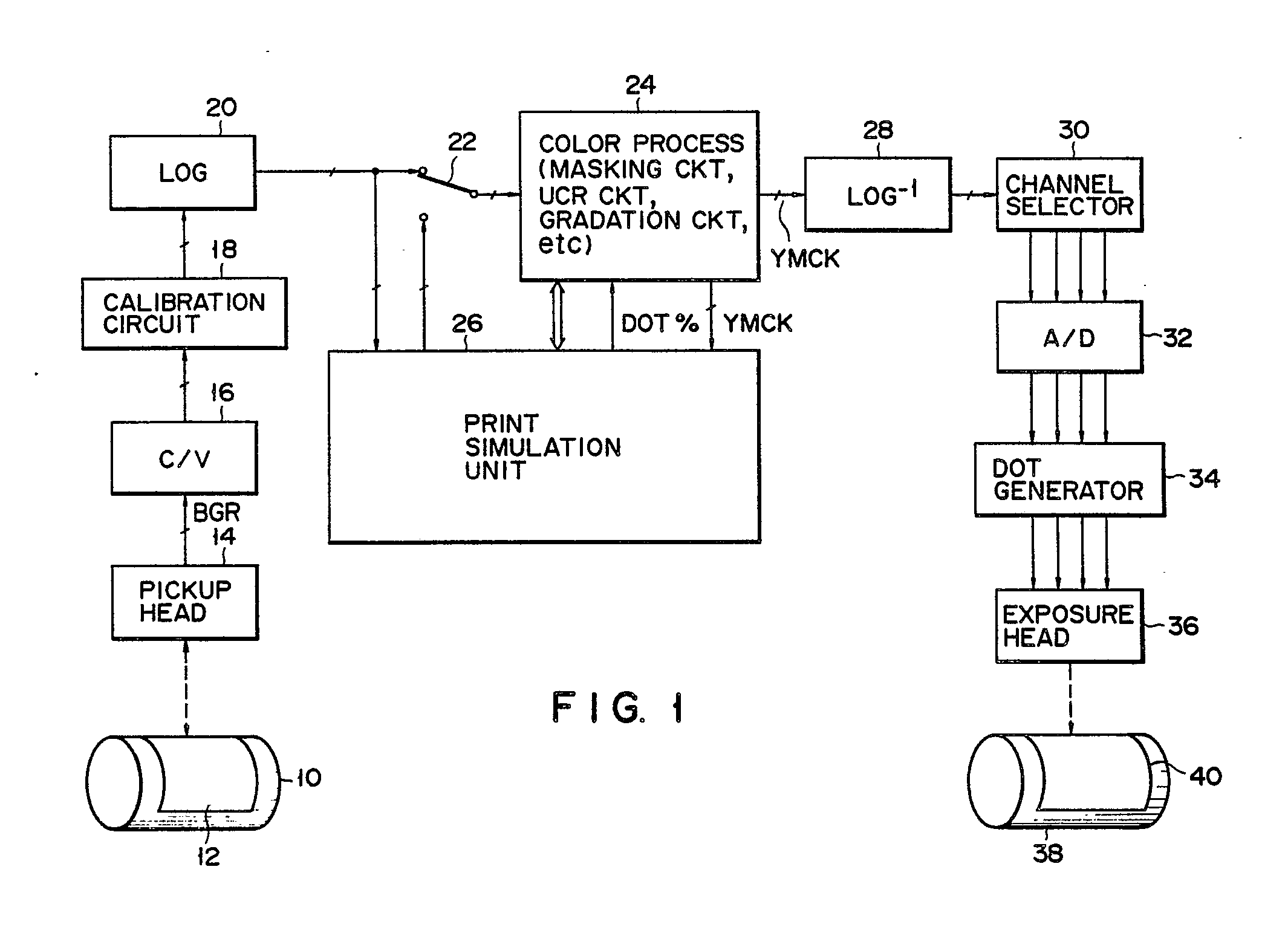
(57) A color original is picked up by a pickup head (14) and B, G, and R image signals
obtained are supplied to a color process circuit (24) including masking correction,
under-color removal, and gradation correction circuits. The output Y, M, C, and K
image signals from the color process circuit (24) are supplied to an exposure head
(36), thus forming a color separation plate. A print simulation unit (26) having a
first and second frame memories (62, 76) is connected in parallel with the color process
circuit (24). The B, G, and R signals are written in a first frame memory (62). The
signal read out from the first frame memory (62) is supplied to the color process
circuit (24) and is color-corrected. The output from the color process circuit (24)
is written in a second frame memory (76). The output from the second frame memory
(76) is displayed on a color monitor (86). The second frame memory (76) stores two
frames, and can display two frames on the color monitor (86) for comparison. The second
frame memory (76) has a data latch (112) for latching a predetermined pixel signal,
and a circuit (120) for synthesizing the latched data in place of a predetermined
pixel signal of the image signals. The second frame memory (76) further has a comparator
(118) for detecting a pixel of the image signals having a level higher than a highlight
set level, and a circuit (110, 112, 114, 116) for flashing the pixel having a level
higher than the highlight set level.
|
|
