| (19) |
 |
|
(11) |
EP 0 202 201 B1 |
| (12) |
EUROPEAN PATENT SPECIFICATION |
| (45) |
Mention of the grant of the patent: |
|
05.09.1990 Bulletin 1990/36 |
| (22) |
Date of filing: 05.05.1986 |
|
|
| (54) |
Lubricating oil filter for internal combustion engines, particularly of motor vehicles,
with members for monitoring the degree of clogging of the filtration surface
Ölfilter für Schmierung von Brennkraftmaschinen, insbesondere von Motorfahrzeugen,
mit Einrichtungen zum Anzeigen des Verstopfungsgrades der Filteroberfläche
Filtre à huile pour moteurs à combustion interne, en particulier les véhicules à moteur,
avec des moyens d'indication du degré de colmatage de la surface filtrante
|
| (84) |
Designated Contracting States: |
|
AT BE CH DE FR GB LI LU NL SE |
| (30) |
Priority: |
06.05.1985 IT 4804785
|
| (43) |
Date of publication of application: |
|
20.11.1986 Bulletin 1986/47 |
| (73) |
Proprietor: ITAL IDEE s.r.l. |
|
00144 Roma (IT) |
|
| (72) |
Inventor: |
|
- Cantoni, Angelo
I-00144 Rome (IT)
|
| (74) |
Representative: Cavattoni, Fabio et al |
|
Cavattoni & Raimondi
Viale dei Parioli, 160
00197 Roma
00197 Roma (IT) |
| (56) |
References cited: :
DE-A- 2 335 276
GB-A- 2 089 479
|
FR-A- 1 482 927
|
|
| |
|
|
|
|
| |
|
| Note: Within nine months from the publication of the mention of the grant of the European
patent, any person may give notice to the European Patent Office of opposition to
the European patent
granted. Notice of opposition shall be filed in a written reasoned statement. It shall
not be deemed to
have been filed until the opposition fee has been paid. (Art. 99(1) European Patent
Convention).
|
[0001] The present invention relates to a lubricating oil filter for internal combustion
engines, particularly of motor vehicles, with members for monitoring the degree of
clogging of the filtration surface.
[0002] Internal combustion engines are provided with a forced-circulation lubrication circuit
the purpose of which is to maintain a lubricating oil film between all those mechanical
parts undergoing . relative movement, in order to reduce their friction and to remove
and dissipate the heat generated.
[0003] With the passage of time, impurities accumulate in the lubricating oil, these impurities
consisting mainly of metal particles deriving from the wear of the engine sliding
members, carbon particles produced by the fuel and by the combustion of the seeping
oil, and mineral powders, generally siliceous and calcareous, deriving from the dust
suspended in the intake air.
[0004] In order to eliminate these solid particles, which with the passage of time lead
to considerable wear of the moving parts of the engine, a filter cartridge in the
form of a thin sheet metal casing containing a folded paper cylinder, and a valve
system for controlling the passage of oil are usually provided.
[0005] These filters comprise a pressure relief valve connected as a bypass, to ensure oil
feed to the engine even when the oil pressure downstream of the valve is insufficient,
due either to operation at high speed or to clogging of the filter.
[0006] When this valve opens it on the one hand ensures correct lubrication, even if the
filter is clogged, but on the other hand enables not only the oil but also impurities
contained in it to circulate through the engine members, to produce the aforesaid
damage. It is therefore of particular importance to determine the state of clogging
of the oil filter in order to be able to replace it as soon as it has exceeded its
limiting operational state before the pressure relief valve is subjected to too frequent
opening movements or before the oil passing through it undergoes high pressure drop,
without having to rely on an estimate of average life as in the case of filters known
up to the present time.
[0007] GB-A-2 089 479 discloses a lubricating oil filter with members for monitoring the
degree of clogging of the filtration surface.
[0008] According to the present invention there is provided a lubricating oil filter for
internal combustion engines, particularly of motor vehicles, with members for monitoring
the degree of clogging of the filtration surface, and comprising an outer casing which
is provided with an end cover connectable to the engine lubrication circuit and containing
passages for oil inlet and outlet, and which houses a filter element through which
the oil passes, there also being provided a pressure relief valve which prevents the
oil passing through said filter element in the case of excessive pressure drop, the
pressure relief valve being provided with means for connecting an electrical conductor
to earth in the case of high pressure drop in the oil flow through the filter element,
and with further means for connecting the electrical conductor leading to the outside
of the filter to earth following repeated opening movements of the pressure relief
valve, there being provided an instrument for indicating when the electrical conductor
leading to the outside of the filter has been connected to earth, characterised by
further comprising mutually facing metal plates separated by the filter element and
arranged to form a capacitor, of which the filter element forms the dielectric, one
of the plates being connected to the vehicle earth and the other being connected to
an electrical conductor leading to the outside of the filter, there being further
provided an instrument for measuring the capacitance of said capacitor.
[0009] Considering the invention in greater detail, in one embodiment the filter element
is supported internally by a metal grid which forms one of the plates of said capacitor,
it being electrically connected to the electrical conductor leading to the outside
of the filter.
[0010] According to a further embodiment, the outer casing of the filter is of metal material
which is electrically isolated from the metal support grid for the filter element
and is connected to the vehicle earth, to form the second plate of said capacitor,
or, if the outer casing is of a nonconducting material, externally to the filter element
and facing the metal grid there is provided a metal element which is electrically
isolated from the grid and is connected electrically to the vehicle earth, to form
the second plate of the capacitor.
[0011] The pressure relief valve comprises a cylinder in which a piston can slide againstfriction
and has one of its faces in hydraulic communication with the zone upstream of the
filter element and its other in communication with the zone downstream of the filter
element, with respect to the oil path through the filter, there being provided a pair
of separated electrical contacts one of which is connected to the vehicle earth and
the other is connected to the electrical conductor leading to the outside of the filter,
they being arranged to come into mutual electrical contact, so closing the circuit
which connects the conductor to earth, when the piston reaches the end of its stroke
of travel within the cylinder, this travel being due to the existence of a pressure
difference between its faces which produces a thrust exceeding the friction resistance
which opposes its sliding.
[0012] According to a further embodiment of the present invention, in the pressure relief
valve there is a cylinder in which a piston can slide against friction, one of its
faces being in hydraulic communication with the zone downstream of the filter element
with respect to the oil path through the filter, and the other face being in communication
with a zone through which the oil passes when the pressure relief valve is open, there
being provided a pair of electrical contacts arranged to be urged into mutual contact
by said piston when it reaches the end of its stroke of travel within the cylinder,
this travel being due to successive opening movements of the pressure relief valve,
and thus closing the circuit for connecting the electrical conductor to earth.
[0013] Alternatively, the means for connecting the conductor to earth following repeated
opening movements of the pressure relief valve can be formed from a layer of insulating
material applied to the sealing surface of the valving member of the pressure relief
valve and electrically separating said valving member from its closure seat, the valving
member and the closure seat being electrically conducting and connected to the vehicle
earth and to the electrical conductor leading to the outside of the filter, the insulating
material forming the layer applied to the valving member being constituted by a material
which can be eroded by the oil flow through the pressure relief valve when this is
open.
[0014] An electrical capacity meter can be connected to the electrical conductor leading
to the outside of the filter in order to measure the capacitance of the capacitor,
which capacity meter can be calibrated in relation to the electrical characteristics
of the type of filter measured and can provide an indication of the effective capacitance
of the capacitor, which is variable up to a value which indicates the need for replacing
the filter.
[0015] Alternatively, an instrument for measuring the capacitance of the capacitor and/or
for indicating the closure of the electrical contacts can be permanently mounted on
the vehicle and connected to said electrical conductor, and comprise an electronic
circuit arranged to cause a signal to appear on the dashboard when the capacitance
of the capacitor passes beyond a predeterminated value and/or when the electrical
contacts close.
[0016] Further details will be apparent from the description given hereinafter with reference
to the accompanying drawings, which illustrate embodiments of the invention and in
which:
Figure 1 is an overall sectional view of a filter according to the invention;
Figure 2 shows the electrical circuit diagram of the filter;
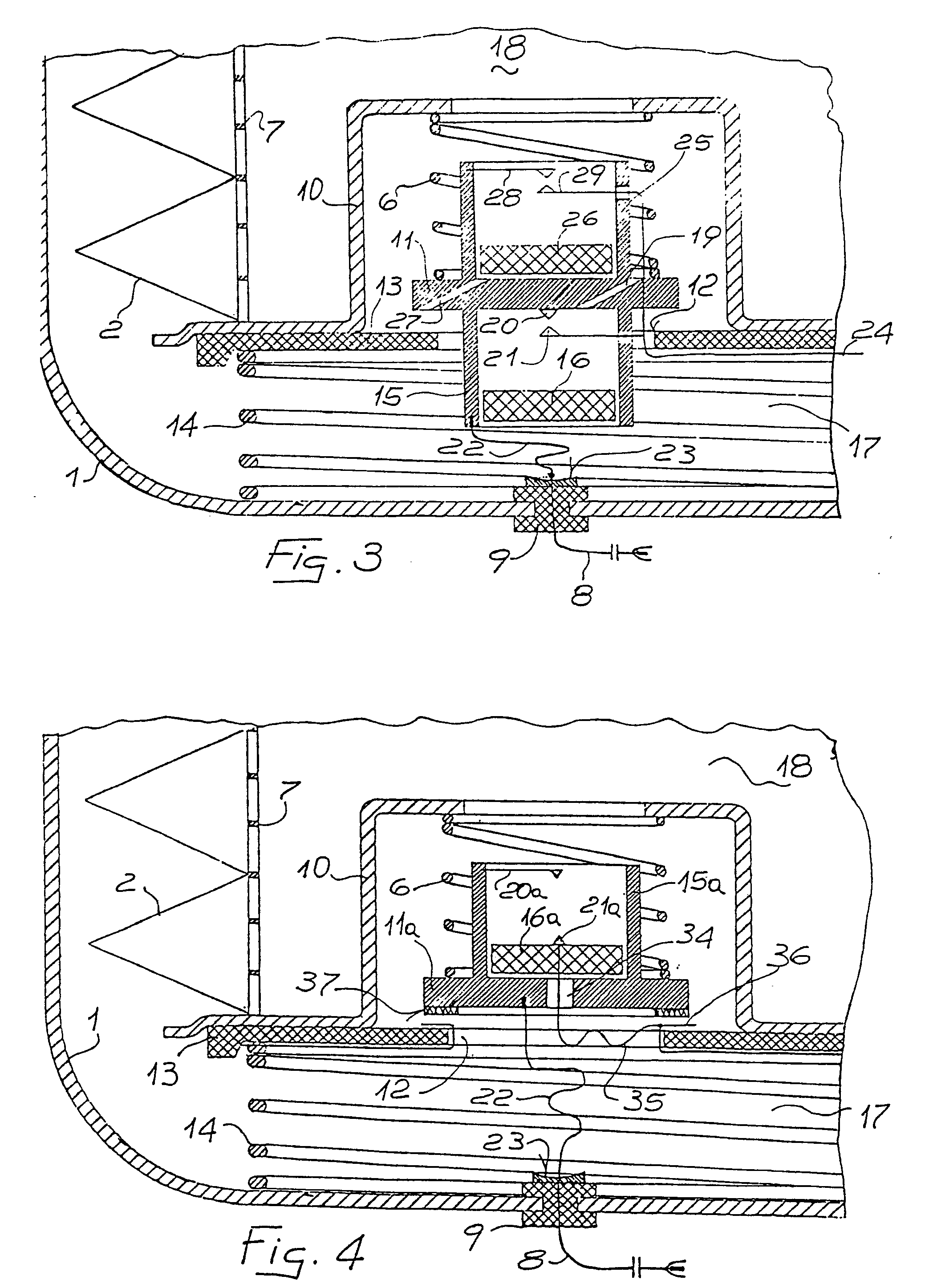
Figure 3 is a partial section through the lower portion of one embodiment of the filter
according to the invention;
Figure 4 is a partial section through the lower portion of a second embodiment of
the filter; and
Figure 5 is an example of an electrical connection diagram for feeding a signal to
the dashboard.
[0017] As shown in Figure 1, the filter according to the invention consists of an outer
casing 1, usually of metal material, which encloses a paper filter element 2 and is
connected to the engine lubrication circuit by way of the threaded connector 3 on
its end cover 4. The oil path through its interior is shown diagrammatically by the
arrows in the figure, and is such as to traverse the paper element, which is constructed
with a large passage surface to minimise the pressure drop of the oil flow through
it.
[0018] There is also provided a pressure relief valve 5 fitted with a return spring 6. When
open, the valve allows the oil to pass freely through the filter by bypassing the
filter element 2, if this latter is clogged or during high-speed operation, in order
to ensure in all cases that sufficient oil passes.
[0019] The filter element 2 is supported internally by a metal grid 7 which is electrically
isolated from the outer casing 1. In the filter according to the invention, the grid
7 and outer casing 1 form the plates of a capacitor, of which the filter element 2
constitutes the dielectric. The outer casing 1 is connected to the vehicle earth,
whereas the grid 7 is connected by way of the metal parts of the pressure relief valve
5 to a conductor 8, which leaves the filter through the insulating bush 9.
[0020] As shown in Figure 3, the pressure relief valve 5 is formed from a metal capsule
10 in electrical contact with the grid 7 and containing a valving member 11, which
is urged by the spring 6 to form a seal against the central aperture 12 of a bush
13 of insulating material. The bush 13, the capsule 10, the grid 7 and the filter
element 2 are kept in position by a spring 14 acting against the outer casing 1 of
the filter.
[0021] The valving member 11 comprises a cylinder 15 in which a piston 16 of semi-rigid
plastics material can slide under the action of a pressure difference between the
zone 17 upstream of the filter element 2, and the zone 18 downstream of said filter
element. Communication between the zone 18 and the relative face of the piston 16
is obtained by means of a sized bore 19.
[0022] The valving member 11 is constructed of a conducting material and comprises a fixed
electrical contact 20 and an electrical contact 21 which is mobile under the action
of the piston 16 as this latter reaches the end of its stroke, to close the electrical
circuit between the contacts 20 and 21.
[0023] The valving member 11 is connected electrically to the cable 22, which is able to
follow its opening and closure movements, and rests against the metal disc 23 of the
bush 9, and the mobile contact 21 is connected to the outer casing 1, and from there
to the vehicle earth, by means of the conductor 24 which is in contact with the spring
14.
[0024] In the upper part of the valving member 11 there is a cylinder 25 in which a sliding
piston 26 is disposed. There opens on to the lower face of the piston 26 a sized bore
27, which is closed when the valving member 11 is lowered to seal against the bush
13, and is open when the valving member is raised by the effect of excessive pressure
drop in the oil flow through the filter element.
[0025] At the upper end of the cylinder 25 there are a fixed electrical contact 28 and a
mobile electrical contact 29, which is separated from the preceding until the piston
26 is raised and acts against it.
[0026] This happens should the valving member 11 undergo multiple opening movements, which
enable the oil, under high pressure in this zone, to pass through the bore 27 to apply
to the lower face of the piston 26 a pressure which is greater than that existing
in the zone 18, and thus cause the piston 26 to successively advance until it pushes
against the- mobile contact 29.
[0027] Figure 2 shows the electrical circuit diagram of the filter according to the invention,
comprising the capacitor 30 formed by the outer casing 1 and grid 7 of the filter,
and the electrical contacts 20, 21 and 28, 29, which are open under normal operating
conditions.
[0028] Having access to the conductor 8, it is therefore possible to measure the capacitance
of the capacitor 30, which varies with the progressive deposition of particles on
the filtration surface and thus with the degree of filter clogging.
[0029] If calibrated to take account of the electrical characteristics of the filter, the
calibration possibly being supplied as an identification code for the filter itself,
an instrument connected to the conductor 8 can measure the capacitance of the capacitor
30, to indicate its variation until it passes beyond the value corresponding to a
degree of clogging which requires replacement of the filter. The closure of the contacts
20, 21 or 28, 29 short-circuits the capacitor plates formed by the outer casing 1
and grid 7 of the filter, to give an immediate indication that the limits of correct
filter operation have been exceeded.
[0030] A capacity measuring instrument could be connected to the conductor 8 only when it
is required to check the filter operation, and in this case the end of the conductor
8 would be provided with an electrical connection pin for connection to a contact
cable of this instrument.
[0031] A measuring instrument could also be permanently installed on the vehicle, for example
in accordance with the diagram of Figure 5. In this case, the instrument 31 is connected
to the conductor 8 by its own contact cable 32, and possesses an electronic circuit
which, when the instrument indicates the predetermined capacitance change or when
said contacts 20, 21 or 28, 29 close, causes that warning lamp 33 which normally exists
on the dashboard and is connected to the pressure switch of the oil circuit to light
for example with an intermittent signal. In this manner, a precise indication of the
state of wear of the filter is given on the vehicle dashboard, without requiring the
installation of a further warning lamp on the dashboard.
[0032] Figure 4 shows an alternative embodiment of the filter according to the invention,
in which the valving member 11 a of the pressure relief valve 5 is provided with a
cylinder 15a carrying a piston 16a which, when it reaches the end of its stroke of
travel within the cylinder 15a, urges its mobile contact 21a into electrical contact
with the fixed contact 20a. The lower face of the piston is in hydraulic communication
with the zone 17 by means of a duct 34 through which there also passes the flexible
cable 35 which connects the mobile contact 21a to the spring 14 and to the outer casing
1 of the filter.
[0033] In order to indicate that the filter pressure relief valve has opened an excessive
number of times, the cylinder 25 and piston 26 of Figure 3 are replaced by a conducting
element 36 on the bush 13, connected electrically to the spring 14 and casing 1. When
in its closed position, the valving member 11a is kept electrically isolated from
said conducting element 36 by a gasket 37 of insulating material. This insulating
material, of small thickness, for example a few tenths of a millimetre, is able to
be progressively eroded by the high-velocity oil flow which occurs during opening
of the valving member 11 a. When sufficient erosion of the gasket 37 has taken place
following repeated opening and closure movements of the valving member, electrical
contact is made between the valving member and conductor 36, to indicate that the
filter requires replacing.
[0034] A filter according to the invention can be provided with the three described elements
sensitive to clogging, i.e. plates for capacitance measurements, contacts arranged
to close if a high pressure drop across the filter element persists, and contacts
arranged to close following a large number of opening movements of the pressure relief
valve. However, even only one of said sensitive elements could be provided, as each
of them is sufficient to provide a valid indication of the reduced operability of
the filter.
[0035] If the capacitive element is present, the measuring instrument has to be calibrated
for each type of filter. This calibration need be carried out only once on assembly
if the measuring instrument is mounted in the vehicle, whereas if the measuring instrument
is used for several different vehicles using filters of different types, for example
for workshop use, the calibration has to be made at each measurement, there being
provided an identification code for the electrical characteristics of the filter,
on the basis of which the calibration values of the instrument are chosen.
1. A lubricating oil filter for internal combustion engines with members for monitoring
the degree of clogging of the filtration surface, comprising an outer casing which
is provided with an end cover connectable to the engine lubrication circuit and containing
passages for oil inlet and outlet, and which houses a filter element through which
the oil passes, there also being provided a pressure relief valve which prevents the
oil passing through said filter element in the case of excessive pressure drop, the
pressure relief valve being provided with means for connecting an electrical conductor
to earth in the case of high pressure drop in the oil flow through the filter element,
and with further means for connecting the electrical conductor leading to the outside
of the filter to earth following repeated opening movements of the pressure relief
valve, there being provided an instrument for indicating when the electrical conductor
leading to the outside of the filter has been connected to earth, characterised by
further comprising mutually facing metal plates separated by the filter element and
arranged to form a capacitor, of which the filter element (2) forms the dielectric,
one of the plates being connected to the vehicle earth and the other being connected
to an electrical conductor (8) leading to the outside of the filter, there being further
provided an instrument for measuring the capacitance of said capacitor.
2. A lubricating oil filter according to claim 1, characterised in that the filter
element (2) is supported internally by a metal grid (7) which forms one of the plates
of the capacitor, it being electrically connected to the electrical conductor (8)
leading to the outside of the filter.
3. A lubricating oil filter according to any of claims 1 and 2, characterised in that
the outer casing (1) of the filter is of metal material which is electrically isolated
from the metal support grid (7) for the filter element (2) and is connected to the
vehicle earth, to form the second plate of said capacitor.
4. A lubricating oil filter according to any of claims 1 and 2, characterised in that
externally to the filter element (2) and facing the metal grid (7) there is provided
a metal element which is electrically isolated from the grid and is connected electrically
to the vehicle earth, to form the second plate of said capacitor.
5. A lubricating oil filter according to any of claims 1 to 4, characterised in that
the pressure relief valve (5) comprises a cylinder (15, 15a) in which a piston (16,
16a) can slide against friction and has one of its faces in hydraulic communication
with the zone (17) upstream of the filter element (2) and its other in communication
with the zone (18) downstream of the filter element (2), with respect to the oil path
through the filter, there being provided a pair of separated electrical contacts (20-21,
20a-21a) one of which is connected to the vehicle earth and the other is connected
to the electrical conductor (8) leading to the outside of the filter, they being arranged
to come into mutual electrical contact, so closing the circuit which connects the
conductor to earth, when the piston (16, 16a) reaches the end of its stroke of travel
within the cylinder (15, 15a), this travel being due to the existence of a pressure
difference between its faces which produces a thrust exceeding the friction resistance
which opposes its sliding.
6. A lubricating oil filter according to any of claims 1 to 5, characterised in that
in the pressure relief valve (5) there is a cylinder (25) in which a piston (26) can
slide against friction and has one of its faces in hydraulic communication with the
zone (18) downstream of the filter element (2), with respect to the oil path through
the filter, and its other face in communication with a zone (17) through which the
oil passes when the pressure relief valve (5) is open, there being provided a pair
of electrical contacts (28, 29) arranged to be urged into mutual contact by said piston
(26) when it reaches the end of its stroke of travel within the cylinder (25), this
travel being due to successive opening movements of the pressure relief valve (5),
and thus closing the circuit which connects the electrical conductor (8) to earth.
7. A lubricating oil filter according to any of claims 1 to 5, characterised in that
the means for connecting the conductor (8) to earth following repeated opening movements
of the pressure relief valve (5) are formed from a layer (37) of insulating material
applied to the sealing surface of the valving member (11a) and electrically separating
said valving member (11a) from its closure seat, the valving member (11a) and the
closure seat being electrically conducting and connected to the vehicle earth and
to the electrical conductor (8) leading to the outside of the filter, the insulating
material forming the layer (37) applied to the valving member (11a) being erod- able
by the oil flow through the pressure relief valve (5) when this is open.
8. A lubricating oil filter according to any of claims 1 to 7, characterised in that
an electrical capacity meter can be connected to the electrical conductor (8) leading
to the outside of the filter in order to measure the capacitance of the capacitor,
which capacity meter can be calibrated in relation to the electrical characteristics
of the type of filter measured, to provide an indication of the effective capacitance
of the capacitor, which is variable up to a value which indicates the need for replacing
the filter.
9. A lubricating oil filter according to any of claims 1 to 8, characterised in that
an instrument for measuring the capacitance of the capacitor and/or for indicating
the closure of the electrical contacts can be permanently mounted on the vehicle and
connected to said electrical conductor (8), and comprise an electronic circuit arranged
to cause a signal to appear on the dashboard when the capacitance of the capacitor
passes beyond a predetermined valve and/or when said electrical contacts close.
10. A lubricating oil filter according to claim 9, characterised in that the electronic
circuit causes the warning lamp connected to the oil circuit pressure switch and already
present on the motor vehicle dashboard to light, for example with an intermittent
signal.
1. Ölfilter für Brennkraftmaschinen mit Einrichtungen zum Anzeigen des Verstopfungsgrades
der Filterfläche, umfassend ein Außengehäuse, das mit einer Endabdeckung versehen
ist, welche mit dem Schmierungskreislauf der Maschine verbunden ist und Durchlaßkanäle
für den Einlaß und den Auslaß von Öl enthält, und in dem sich ein Filterelement befindet,
durch das das Öl hindurchtritt, und weiterhin mit einem Überdruckventil, das den Öldurchtritt
durch das Filterelement im Fall von übermäßigem Druckabfall verhindert und das mit
Einrichtungen zum Anschließen eines elektrischen Leiters an Masse im Fall des hohen
Druckabfalls im Ölstrom durch das Filterelement und mit weiteren Einrichtungen zum
Verbinden des aus dem Filter herausführenden elektrischen Leiters mit Masse als Folge
wiederholter Öffnungsbewegungen des Überdruckventils versehen ist, und mit einem Instrument
zur Anzeige, wenn der aus dem Filter herausführende elektrische Leiter mit Erde verbunden
worden ist, weiterhin gekennzeichnet durch einander gegenüberliegende und durch das
Filterelement getrennte Metallplatten, die zur Bildung eines Kondensators angeordnet
sind, dessen Dielektrikum das Filterelement (2) bildet, wobei eine der Platten mit
der Fahrzeugmasse und die andere mit einem elektrischen Leiter (8), der aus - dem
Filter herausführt, verbunden ist, und durch ein Instrument zum Messen der Kapazität
des Kondensators.
2. Ölfilter nach Anspruch 1, dadurch gekennzeichnet, daß das Filterelement (2) innenseitig
von einem Metallgitter (7) abgestützt ist, das eine der Kondensatorplatten bildet
und elektrisch mit dem elektrischen Leiter (8), der aus dem Filter herausführt, verbunden
ist.
3. Ölfilter nach Anspruch 1 oder 2, dadurch gekennzeichnet, daß das Außengehäuse (1)
des Filters aus einem Metallmaterial besteht, das elektrisch vom metallenen Stützgitter
(7) für das Filterelement (2) getrennt ist, und mit der Fahrzeugmasse verbunden ist,
um die zweite Kondensatorplatte zu bilden.
4. Ölfilter nach Anspruch 1 oder 2, dadurch gekennzeichnet, daß sich außerhalb des
Filterelements (2) und dem Metallgitter (7) gegenüberliegend ein Metallelement befindet,
das vom Gitter elektrisch getrennt ist und elektrisch mit der Fahrzeugmasse verbunden
ist, um die zweite Platte des Kondensators zu bilden.
5. Ölfilter nach einem der Ansprüche 1 bis 4, dadurch gekennzeichnet, daß das Überdruckventil
(5) einen Zylinder (15, 15a) umfaßt, in dem ein Kolben (16, 16a) entgegen einer Reibungskraft
gleiten kann und mit einer seiner Flächen in hydraulischer Kommunikation mit der strömungsoberhalb
des Filterelements (2) befindlichen Zone (17) steht und mit seiner anderen Fläche
in Kommunikation mit der strömungsunterhalb des Filterelements (2) befindlichen Zone
(18) steht, hinsichtlich des Ölwegs durch das Filter gesehen, und daß zwei getrennte
elektrische Kontakte (20-21, 20a-21a) vorhanden sind, vondenen einer mit der Fahrzeugmasse
und der andere mit dem aus dem Filter herausführenden elektrischen Leiter (8) verbunden
ist und die so angeordnet sind, daß sie in gegenseitigen elektrischen Kontakt kommen,
um den Kreis zu schließen, der den Leiter mit Masse verbindet, wenn der Kolben (16,
16a) das Ende seines Hubs im Zylinder (15, 15a) erreicht, wobei dieser Hub die Folge
des Vorliegens einer Druckdifferenz zwischen seinen Flächen ist, die einen Schub erzeugt,
der den dem Gleiten entgegenstehenden Reibungswiderstand übertrifft.
6. Ölfilter nach einem der Ansprüche 1 bis 5, dadurch gekennzeichnet, daß sich im
Überdruckventil (5) ein Zylinder (25) befindet, in dem ein Kolben (26) entgegen einer
Reibungskraft gleiten kann, dessen eine Fläche sich in hydraulischer Kommunikation
mit der Zone (18) strömungsunterhalb des Filterelements (2) hinsichtlich des Ölwegs
durch das Filter befindet und dessen andere Fläche sich in Kommunikation mit einer
Zone (17) befindet, durch die das Öl hindurchtritt, wenn das Überdruckventil (5) offen
ist, wobei zwei elektrische Kontakte (28,29) vorhanden sind, die vom Kolben (26) in
gegenseitigen elektrischen Kontakt gedrückt werden, wenn er das Ende seines Hubs,
der die Folge aufein anderfolgender Öffnungsbewegungen des Überdruckventils (5) ist,
im Zylinder (25) erreicht, und somit den Stromkreis schließen, der den elektrischen
Leiter (8) mit Masse verbindet.
7. Ölfilter nach einem der Ansprüche 1 bis 5, dadurch gekennzeichnet, daß die Einrichtung
zum Verbinden des Leiters (8) mit Masse auf wiederholte Öffnungsbewegungen des Überdruckventils
(5) hin durch eine Schicht (37) aus isolierendem Material gebildet ist, die auf die
Dichtfläche des Ventilkörpers (11 a) aufgebracht ist und elektrisch den Ventilkörper
(11a) von seinem Ventil Schließsitz trennt, wobei der Ventilkörper (11 a) und der
Schließsitz elektrisch leitend und mit der Fahrzeugmasse bzw. dem aus dem Filter herausführenden
elektrischen Leiter (8) verbunden sind und das die auf den Ventilkörper (11a) aufgebrachte
Schicht (37) bildende isolierende Material durch den Ölstrom, der durch das Überdruckventil
(5) imgeöffneten Zustand fließt, erodierbar ist.
8. Ölfilter nach einem der Ansprüche 1 bis 7, dadurch gekennzeichnet, daß ein Kapazitätsmesser
zum Messen der elektrischen Kapazität an den aus dem Filter herausleitbaren elektrischen
Leiter (8) zum Messen der Kapazität des Kondensators anschließbar ist und in Bezug
zu den elektrischen Charakteristiken des Typs des gemessenen Filters eichbar ist,
um eine Anzeige der effektiven Kapazität des Kondensators zu ergeben, die bis zu einem
Wert veränderlich ist, der die Notwendigkeit des Ersatzes des Filters anzeigt.
9. Ölfilter nach einem der Ansprüche 1 bis 8, dadurch gekennzeichnet, daß ein Instrument
zum Messen der Kapazität des Kondensators und/oder zum Anzeigen des Verschlusses der
elektrischen Kontakte ständig am Fahrzeug montierbar ist und mit dem elektrischen
Leiter (8) verbindbar ist und eine elektronische 4 Schaltung umfaßt, die gemäß ihrer
Anordnung ein am Armaturenbrett erscheinendes Signal bewirkt, wenn die Kapazität des
Kondensators über einen gegebenen Wert steigt und/oder wenn die elektrischen Kontakte
schließen.
10. Ölfilter nach Anspruch 9, dadurch gekennzeichnet, daß die elektronische Schaltung
die Warnlampe, die mit dem Öldruckschalter verbunden ist und bereits am Kraftfahrzeug-Armaturenbrett
vorhanden ist, zum Aufleuchten bringt, z.B. mit einem Blinksignal.
1. Filtre à huile pour moteur à combustion interne muni d'organes de contrôle du degré
de colmatage de la surface filtrante, comprenant un carter extérieur muni d'un couvercle
d'extrémité pouvant être raccordé au circuit de lubrification du moteur et contenant
des passages pour l'entrée et la sortie d'huile, et qui renferme un élément de filtre
traversé par l'huile, une vanne de sûreté ou de décharge de pression étant également
prévue pour empêcher le passage d'huile à travers cet élément de filtre en cas de
chute de pression excessive, la vanne de sûreté ou de décharge de pression étant munie
de moyens destinés à raccorder un conducteur électrique à la masse en cas de chute
de pression élevée dans le passage d'huile à travers l'élément de filtre, et avec
des moyens supplémentaires pour raccorder à la masse le conducteur électrique menant
à l'extérieur du filtre suivant des mouvements d'ouverture répétés de la vanne de
sûreté ou de décharge de pression, un instrument étant prévu pour indiquer le moment
où le conducteur électrique menant à l'extérieur du filtre est raccordé à la masse,
caractérisé en ce qu'il comprend de plus des plaques métalliques se faisant face,
mutuellement séparées par l'élément de filtre et disposées de façon à former un condensateur
dont l'élément de filtre (2) forme le diélectrique, l'une des plaques étant raccordée
à la masse du véhicule et l'autre étant raccordée à un conducteur électrique (8) menant
à l'extérieur du filtre, un instrument de mesure de la capacitance du condensateur
étant de plus prévu.
2. Filtre à huile selon la revendication 1, caractérisé en ce que l'élément de filtre
(2) est supporté à l'intérieur par une grille métallique (7) qui forme l'une des plaques
du condensateur, raccordé électriquement au conducteur électrique (8) menant à l'extérieur
du filtre.
3. Filtre à huile selon la revendication 1 ou 2, caractérisé en ce que le carter extérieur
(1) du filtre est réalisé en un métal isolé électriquement de la grille de support
métallique (7) pour l'élément de filtre (2) et raccordé à la terre du véhicule pour
former la seconde plaque du condensateur.
4. Filtre à huile selon la revendication 1 ou 2, caractérisé en ce qu'extérieurement
à l'élément de filtre (2) et en regard de la grille métallique (7) est prévu un élément
métallique isolé électriquement de la grille et raccordé à la masse du véhicule pour
former la seconde plaque du condensateur.
5. Filtre à huile selon l'une quelconque des revendications 1 à 4, caractérisé en
ce que la vanne de sûreté ou de décharge de pression (5) comprend un cylindre (15,
15A) dans lequel un piston (16, 16A) peut coulisser en opposition à la friction et
comporte une de ses faces en communication hydraulique avec la zone (17) en amont
de l'élément de filtre (2) et son autre face en communication avec la zone (18) en
aval de l'élément de filtre (2) par rapport au passage d'huile à travers le filtre,
une paire de contacts électriques séparés (20-21, 20a-21a) étant prévus dont l'un
est raccordé à la masse du véhicule et l'autre au conducteur électrique (8) menant
à l'extérieur du filtre, ceux-ci étant disposés de façon à venir en contact électrique
mutuel, fermant ainsi le circuit qui relie le conducteur à la masse, lorsque le piston
(16, 16A) atteint l'extrémité de sa course à l'intérieur du cylindre (15, 15A), cette
course résultant d'un écart de pression entre ses faces, qui produit une poussée dépassant
la résistance à la friction qui s'oppose à son coulissement.
6. Filtre à huile selon l'une quelconque des revendications 1 à 5, caractérisé en
ce que dans la vanne de sûreté ou de décharge de pression (5) est prévu un cylindre
(25) dans lequel un piston (26) peut coulisser en opposition à la friction et a l'une
de ses faces en communication hydraulique avec la zone (18) en aval de l'élément de
filtre (2), par rapport au passage d'huile à travers le filtre, et son autre face
en communication avec une zone (17) traversée par l'huile lorsque la vanne de sûreté
ou de décharge de pression (5) est ouverte, une paire de contacts électriques (28,
29) étant aptes à être mis en contact mutuel forcé par le piston (20) lorsqu'il atteint
la fin de sa course à l'intérieur du cylindre (25), cette course étant provoquée par
les mouvements d'ouverture successifs de la vanne de sûreté ou de décharge de pression
(5), et fermant ainsi le circuit qui relie le conducteur électrique (8) à la masse.
7. Filtre à huile selon l'une quelconque des revendications 1 à 5, caractérisé en
ce que les moyens destinés à raccorder le conducteur (8) à la masse suivant des mouvements
d'ouverture répétés de la vanne de sûreté ou de décharge de pression (5) sont réalisés
à partir d'une couche (37) de matériau isolant appliquée à la surface d'étanchéité
de l'élément de vanne (11A) et séparant électriquement cet élément de vanne (11A)
de son siège de fermeture, l'élément de vanne (11A) et le siège de fermeture étant
conducteurs électriquement et étant raccordés à la masse du véhicule et au conducteur
électrique (8) menant à l'extérieur du filtre, le matériau isolant formant la couche
(37) appliquée à l'élément de vanne (11A) pouvant être érodé par le flux d'huile traversant
la vanne de sûreté ou de décharge de pression (5) lorsque celle-ci est ouverte.
8. Filtre à huile selon l'une quelconque des revendications 1 à 7, caractérisé en
ce qu'un capacimètre électrique peut être raccordé au conducteur électrique (8) menant
à l'extérieur du filtre afin de mesurer la capacité du condensateur, lequel capacimètre"
peut être calibré en fonction de caractéristiques électriques du type de filtre mesuré,
pour fournir une indication de la capacitance effective du condensateur qui est variable
jusqu'à une valeur indiquant la nécessité de remplacer le filtre.
9. Filtre à huile selon l'une quelconque des revendications 1 à 8, caractérisé en
ce qu'un instrument de mesure de la capacitance du condensateur et/ou d'indication
de la fermeture des contacts électriques peut être monté en permanence sur le véhicule
et relié au conducteur électrique (8), et comprend un circuit électronique disposé
de façon à provoquer l'apparition d'un signal sur le tableau de bord lorsque la capacitance
du condensateur dépasse une valeur prédéterminée et/ou lorsque les contacts électriques
se ferment.
10. Filtre à huile selon la revendication 9, caractérisé en ce que le circuit électronique
provoque l'allumage du voyant ou témoin d'avertisseur lumineux raccordé au commutateur
de pression de circuit d'huile et existant déjà sur le tableau de bord du véhicule
automobile, par exemple sous forme d'un signal intermittent.