| (19) |
 |
|
(11) |
EP 0 278 615 B1 |
| (12) |
EUROPEAN PATENT SPECIFICATION |
| (45) |
Mention of the grant of the patent: |
|
17.04.1991 Bulletin 1991/16 |
| (22) |
Date of filing: 25.01.1988 |
|
|
| (54) |
Wheel for a pneumatic tyre
Kraftfahrzeugrad
Roue à pneumatique
|
| (84) |
Designated Contracting States: |
|
CH DE ES FR GB IT LI NL SE |
| (30) |
Priority: |
10.02.1987 GB 8702889
|
| (43) |
Date of publication of application: |
|
17.08.1988 Bulletin 1988/33 |
| (73) |
Proprietor: SP TYRES UK LIMITED |
|
Erdington,
Birmingham B24 9QT (GB) |
|
| (72) |
Inventors: |
|
- Corner, Michael Raymond
Coundon
Coventry CV6 8HT (GB)
- Holmes, Tom
Walmley
Sutton Coldfield B76 8HE (GB)
- Griffiths, Phillip Newell
Sutton Coldfield B76 8NS (GB)
- Kemp, Ian
Wilnecote
Tamworth Staffs (GB)
|
| (74) |
Representative: Stewart, Charles Geoffrey et al |
|
SP TYRES UK LIMITED
Technical Division
Fort Dunlop,
Erdington,
Birmingham B24 9QT
Fort Dunlop,
Erdington,
Birmingham B24 9QT (GB) |
| (56) |
References cited: :
FR-A- 534 003
GB-A- 16 939
US-A- 1 693 192
|
FR-A- 672 929
US-A- 1 689 649
|
|
| |
|
|
|
|
| |
|
| Note: Within nine months from the publication of the mention of the grant of the European
patent, any person may give notice to the European Patent Office of opposition to
the European patent
granted. Notice of opposition shall be filed in a written reasoned statement. It shall
not be deemed to
have been filed until the opposition fee has been paid. (Art. 99(1) European Patent
Convention).
|
[0001] This invention relates to a wheel rim for a pneumatic tyre and in particular to a
single piece wheel rim having two axially spaced tapered bead seats upon which a tyre
may be mounted.
[0002] Conventional single piece wheel rims include between the bead seats a radially inwardly
displaced portion to provide a fitting well. The depth of the fitting well is determined
by the height of the tyre retaining flanges which extend around the wheel rim and
which are axially outside the bead seats and the size of the tyre toe region. Fitting
wells are consequently of substantial depth and this causes the space inside the wheel
rim to be limited.
[0003] Vehicle wheels are, however, in general fitted around the vehicle brakes be they
drum or disc brakes and the need for a fitting well means that the brake space is
limited. This limitation is becoming an increasing problem as greater brake performances
are demanded.
[0004] It is an object of the present invention to provide a wheel rim of one piece construction
which has a substantially reduced fitting well depth whilst still allowing fitting
and stripping of a tyre thus allowing increased brake space for a tyre of given load
carrying capacity.
[0005] According to one aspect of the present invention a one piece wheel rim for a pneumatic
tyre is provided having a pair of axially spaced apart tapered bead seats, a tyre
retaining flange axially outwards of each bead seat characterised by one flange having
a reduced height portion having a length of 0.25 to 0.5 times the bead seat circumference
and the reduced height being such that the flange height, measured from the heel point,
which is the point of intersection of the nominal diameter and the nominal wheel width,
is in the range of 0.15 and 0.6 times the height of the remainder of the flange to
allow tyre fitting.
[0006] The minimal fitting well is of substantially smaller depth than is a normal wheel
rim and may be circumferentially continuous or indeed in some preferred arrangements
be very short in the circumferential direction.
[0007] The minimal fitting well may indeed, for tapered bead seat wheel rims, comprise only
a flat connecting base between the axially inner edges of the bead seats. Thus no
well can be seen as such and the necessary space to accommodate the tyre beads for
fitting and stripping is provided by the bead seat slope to the flat connecting base.
[0008] The reduced depth, shallow fitting well is substantially shallower than normal and
in the case of car rims having a diameter typically between 12 & 17 inches the well
depth is less than 8 mm. In the case of light truck wheel rims having a diameter of
typically 12 to 17 inches the well depth is less than 12 mm and in the case of truck
wheel rims having a diameter of typically 20 to 23 inches the well depth is less than
15 mm.
[0009] The reduced height portion of the flange is preferably of limited effective thickness
including any flange turnover which is less than 0.5 times the effective thickness
of the remainder of the flange. This is to ensure that the necessary skew of the tyre
as it is fitted with part of a bead in the shallow well does not cause even the reduced
height portion to abnormally tension the bead reinforcement on assembly of tyre to
wheel rim. The reduced height portion may have one end which progressively slopes
upwards to the full flange height portion and thus gives a smoothly rising region
over which a tyre bead may easily slide. It may also have one end portion which rises
very steeply so as to provide a step or locating shoulder which can be used to retain
part of a tyre bead in place on the wheel rim whilst a fitting tool is taken over
the other joining portion to fit the bead over the flange.
[0010] When a very similar well is used, or more especially when a flat base is used,additional
means may be provided to allow insertion of the tyre removal tool.
[0011] This means is provided adjacent the reduced height position preferably adjacent to
the steeply rising part of the flange. The means may be a short and narrow depression
or may be formed by means of two small, localised radially outwardly formed projections
on the flat base. In each case the depression or raised projections are positioned
at points which are marked externally on the wheel rim and these may be adjacent to
the tyre engaging part of the bead seats. They serve to raise the tyre bead to allow
insertion of a tyre removal tool. One raised region may be used to provide a tyre
inflation valve mounting point.
[0012] Further features of the present invention including preferred flange shapes and dimensions
for different sizes and types of wheel rims will become apparent from the following
description, by way of example only, of some embodiments in conjunction with the attached
diagrammatic drawings in which:
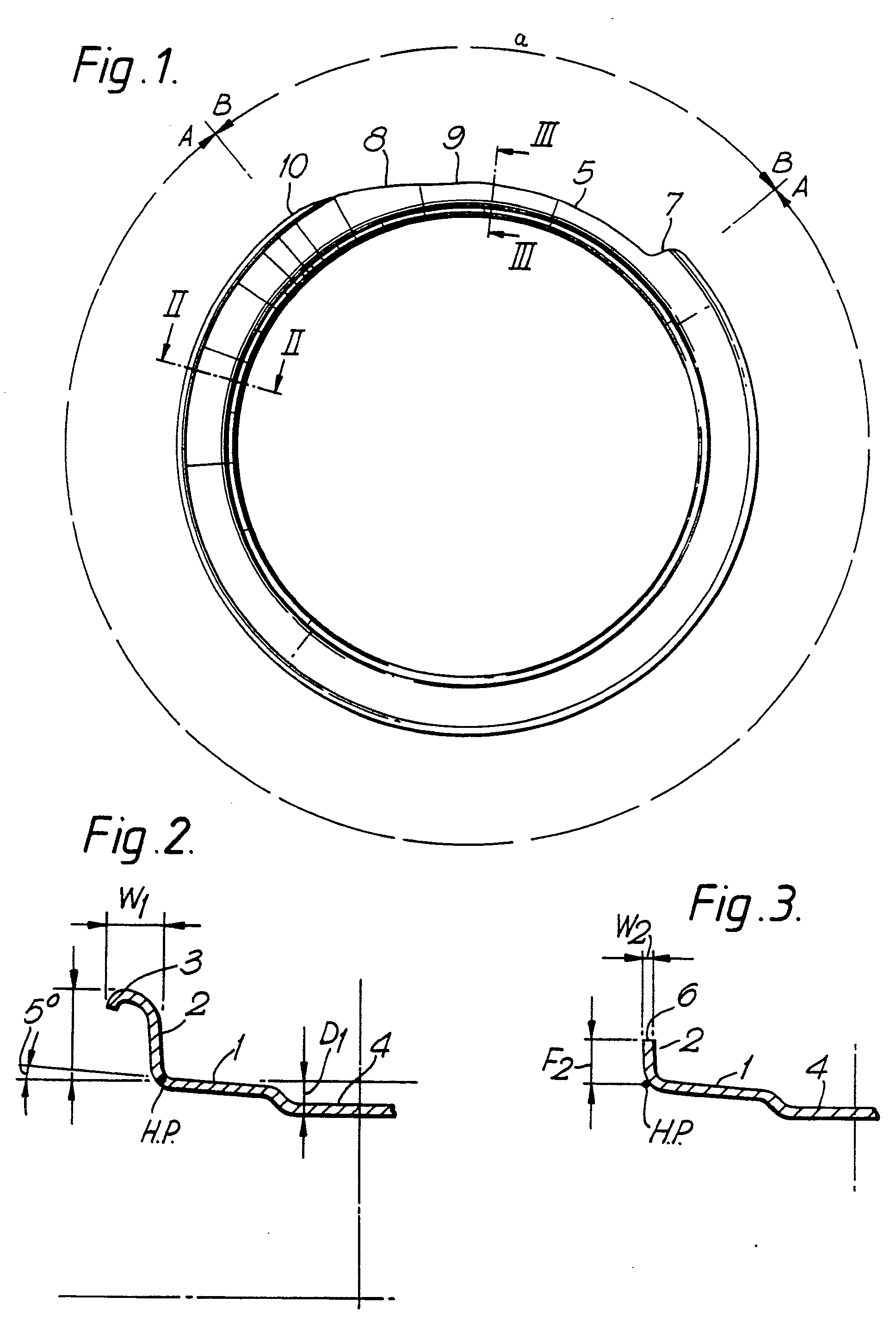
Fig. 1. is a side view of a wheel rim.
Fig. 2. is a part cross section showing one bead seat taken on the line II-II in Fig.
1.
Fig. 3. is a part cross section showing one bead seat taken on the line III-III of
Fig. 1.
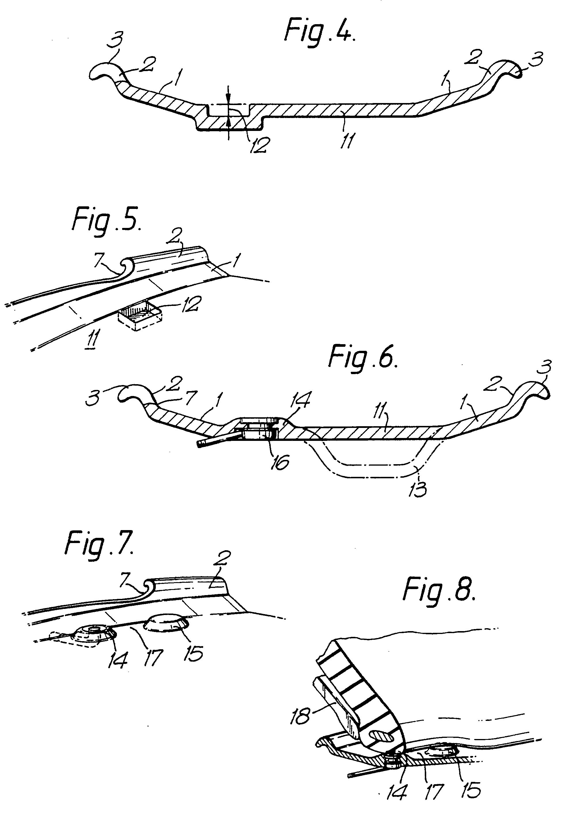
Fig. 4. is a cross section of a wheel rim showing an off-set short well which should
be considered in conjunction with Fig. 5.
Fig. 5. is a scrap perspective view of the short well shown in Fig. 4.
Fig. 6. shows a cross section of a wheel rim with a raised portion incorporating the
tyre inflation valve and should be looked at in conjunction with Fig. 7.
Fig. 7 is a scrap perspective view of Fig. 6.
Fig. 8. shows the tyre removal operation for the assembly of Figs 6 & 7.
[0013] The wheel rim shown in Fig. 1. is a single piece 13˝ diameter car wheel rim without
the centre disc part of the wheel. Fig. 2. shows the conventionally shaped portion
of the wheel rim which extends around the wheel rim in the region marked AA. This
portion has a bead seat 1, tapered at 5 degrees to the axial direction, a bead seat
diameter of 13˝ to suit a 13˝ tyre, a radially projecting tyre retaining flange 2
with outwardly rolled flange edge 3 and a central tyre fitting well 4. The height
F1 of the flange measured from the heel point H.P. is 17.3 mm and the width of the
flange W1 including the rolled edge 3 is 15 mm. maximum.
[0014] The flange has a reduced height portion 5 which extends around the wheel rim for
a distance B-B for this 13˝ car rim is 0.25 times the circumference of the bead seat
1.
[0015] The cross section of the bead seat and flange zone in this portion 5 is shown in
Fig. 3. In this portion the flange 2 has been cut off at 6 to give a flange height
F2 from the heel point of 9 mm and a flange width of 2.5 mm.
[0016] The reduced height portion 5 has one end 7 joined to the normal height portion of
the flange by a stop 7 where the change of height is marked. The other end of the
reduced height portion has a gradually rising region 8 where the flange height increases
progressively between points 9 & 10 which are separated by a distance of 0.12 times
the bead seat circumference.
[0017] Finally, the depth D1 of the tyre fitting well 4 is 4 mm around the complete circumference
of the wheel rim.
[0018] This wheel rim takes a conventional 13˝ car tyre. The tyre can be fitted in a very
similar manner to conventional assembly except that the tyre must be positioned so
that when the bead is engaged in the well at one side the other side is at the reduced
edge portion. Thus to use levers to complete bead fitting entails levering the bead
over the reduced height portion. Advantage can be taken by beginning at the step 7
and working towards the gradually rising region 8 in which case the step 7 retains
the bead in place to assist removal.
[0019] Tyre removal or stripping is the same procedure and the 4 mm well provides space
to initially locate a tyre lever under the bead to commence stripping at the step
7 and again to progress around the reduced heights portion 5 of the wheel rim.
[0020] Another embodiment for a light truck tyre of size 8.5R17.5 utilises a wheel rim of
a very similar type to that described above. In this case, however, the bead seat
taper angle is 15 degrees to suit normal tyres of this type and the full flange height
is 12.7 mm, again as standard. The reduced height portion has a length of.25 times
the bead seat circumference and a height of 6 mm from the bead point. the flange width
in the reduced height region is 4 mm.
[0021] Another embodiment is for a 11R22.5 truck tyre and applies to a cast wheel. Cast
wheels have the same tyre engaging profile as rolled steel wheels but are of greater
material section and this makes the control of flange width in the reduced height
portion more necessary. This rim is again similar to the first embodiment but the
normal flange height in the region A-A is 12.7 mm for the 22.5˝ diameter bead seat
which is also of 15 degrees taper angle. The reduced height portion in this case has
a length of 0.5 times the circumference and a height from the heel point of 6 mm.
The flange width is reduced to 12 mm. Once again a 4 mm deep well is sufficient to
allow tyre fitting and stripping and tyre lever insertion.
[0022] It should be appreciated that various cut away section lengths may be used and also
other heights for the remaining flange. Furthermore, it is not essential to provide
the step 7 and gradually sloping region 8. Two steps 7,or two sloping regions 8 may
be used.
[0023] The embodiment shown in Figs 4 & 5 has tapered bead seats (1) but the main central
portion of the wheel rim comprises a flat base (11) which connects the axially inner
edges of the tapered bead seats. In a small localised region of the wheel adjacent
to the steeply rising portion 7 of the cut-a-way or reduced height portion of the
wheel rim flange 2, is provided a short shallow well having a depth of 3-5 mm. The
circumferential length of this well 12 is about 20 or 30 mm and the axial width is
similar. Thus the wheel rim has no well between the bead seats and the space inside
the wheel is maximised. Nevertheless, for tyre removal it is possible to insert a
tyre lever adjacent to the steeply raising portion 7 and to engage it into the short
well 12 under the tyre bead so that bead removal can be begun using the tyre tool
in the usual way.
[0024] A further embodiment having a similar principle to that previously described for
Figs 4 & 5 is shown in Figs 6, 7 & 8. Once again the wheel rim has a flat face 11
between the axially inner extremities of the two bead seats 1. This may be contrasted
with the broken line which shows a standard shaped wheel well 13. Adjacent to the
flange having the reduced height portion and in the region of the steeply rising portion
7, two localised radially outwardly projecting humps 14 & 15 are provided, these have
a height of between 3-5 mm i.e. are sufficiently low so that on inflating a tyre to
fit it the tyre may move over the raised projection portion 14 & 15 without difficulty.
The projection 14 includes a tyre inflation valve assembly 1b as shown in Fig 6. This
tyre inflation valve 1b is set into the axially inner surface of the flat base 11
and thus provides for inflation of the tyre without any projection radially inwards
of the inner surface of the flat base 11. Thus very much increasing and maximising
the brake space within the wheel.
[0025] When a tyre is to be removed from the wheel rim of Figs 6 & 7 the operation is that
shown in Fig 8 and is broadly similar to that of the embodiments of Figs 4 & 5 in
that the tyre bead when it is pushed from its flange and off its retaining seat, is
located upon the two raised portions 14 & 15, and this allows a tyre lever 18 to be
inserted in the space 17 which is created between the tyre and the two humps. Thus
tyre removal can proceed in the usual way. It should of course be remembered that
the location of the two humps, as in the case of the small well 12 of the previous
embodiment, may conventiently be need to the steeply rising portion itself of the
cut-a-way wheel rim flange and thus it is quite easy to locate the tyre tool into
the right regions despite the fact that the raised projections cannot be seen. In
fact the correct place for the tool is between the valve and the steeply raising portion
7 and this can easily be found.
[0026] The cut-a-way flange may be used on one wheel rim flange or on both wheel rim flanges.
It is preferred however, to use the cut-a-way flange on the inner flange of the wheel
rim, in the sense of being the inner flange when fitted to the vehicle. This provides
an assembly where the cut-a-way flange is inboard of the vehicle.
[0027] The invention may be used with any of the normal bead retention devices including
small tyre bead retaining humps, large tyre bead retention humps in conjunction with
comparatively deep bead seats, or indeed with the tyre and wheel rim system known
as the TD system where a projecting toe is provided on the tyre toe and an accommodating
groove is formed in the wheel rim adjacent to the tapered bead seat.
[0028] Rebalancing of the wheel rim is preferably arranged by providing additional material
in the requisite places. This is of course most conveniently done when the wheel is
cast.
1. A one piece wheel rim for a pneumatic tyre having a pair of axially spaced tapered
bead seats, a tyre retaining flange axially outwards of each bead seat characterised
by a minimal tyre fitting well (4, 12, 17) and by one flange (2) having a reduced
height portion (a) having a length of 0.25 to 0.5 times the bead seat circumference
and the reduced height being such that the flange height, measured from the heel point,
(HP) which is the point of intersection of the nominal diameter and nominal wheel
width,is in the range of 0.15 and 0.6 times the height of the remainder of the flange
(2) to allow tyre fitting and removal.
2. A wheel rim according to claim 1 characterised by the depth of the fitting well
(4, 12, 17) being not more than 8 mm for a 5 degree tapered bead seat car wheel rim
of 12 to 17 inch nominal diameter.
3. A wheel rim according to claim 1 characterised by the depth of the fitting well
(4, 12, 17) being not more than 12 mm for a 15 degree tapered bead seat wheel rim
of 17 to 19 inch nominal diameter.
4. A wheel rim according to claim 1 characterised by the depth of the fitting well
(4, 12, 17) being not more than 15 mm for a 15 degree tapered bead seat truck wheel
rim of 20 to 23 inches nominal diameter.
5. A wheel rim according to claim 1, 2, 3, or 4 characterised by the flange (2) in
the reduced height portion (5) having an effective thickness, including any flange
turnover, measured in the axial direction of the wheel rim, which is less than 0.5
times the effective thickness in the remaining portion of the flange.
6. A wheel rim according to any one of claims 1 to 5 characterised by the reduced
height portion of the flange (5) having at one end of said portion a joining portion
(8) the full height portion in which the flange height increases progressively between
the two heights over a circumferential distance of between 0.1 and 0.3 of the length
of the circumference of the wheel rim such that a gently rising flange region (8)
is provided.
7. A wheel rim according to claim 6 characterised in that the reduced height portion
has at one end of the said portion a second joining portion (7) in which the flange
height changes rapidly to provide a step in the flange against which a tyre bead may
be locked to assist tyre removal or fitting to the wheel rim.
8. A wheel rim according to any one of claims 1 to 7 characterised by the bead seats
(1) having a taper of 5 degrees and a bead seat diameter of 12˝ to 17˝ and the reduced
height portion has a length of 0.25 of the circumferential length of the bead seat,
a height between 5 and 7 mm
9. A wheel rim according to any one of claims 1 to 7 characterised by the bead seats
(1) having a taper of 15 degrees and a diameter in the range of 17˝ to 19˝ and the
reduced height portion has a length of.25 that of the bead seat circumference, a height
of 3.5 to 4.5 mm.
10. A wheel rim according to any one of claims 1 to 7 characterised by the bead seats
(1) having a taper of 15 degrees and a diameter of 20˝ to 23˝ and the reduced height
portion has a length of 0.5 of the bead seat circumference, a height of 3.5 to 4.5
mm and a flange thickness of 10 to 15 mm.
11. A wheel rim according to any of claims 1 to 10 characterised by the fitting well
(12) being very short in the circumferential direction and being adjacent to the reduced
height portion (9) so that a tyre removal tool may be engaged under a tyre bead by
using said short fitting well.
12. A wheel rim according to any one of claims 1 to 10 characterised by a flat base
(11) between the bead seats (1) and adjacent to the reduced height portion (7) a pair
of axially spaced, radially outwardly extending projections (10, 15) adjacent to the
bead seat region (1) so that a tyre bead is lifted from the base by the projections
(10, 15) to allow insertion of a tyre removal tool.
13. A wheel rim according to claim 12 characterised by a tyre inflation valve (16)
being provided in one of the projections (14, 15).
1. Jante de roue d'une seule pièce pour un pneumatique ayant une paire de sièges de
talon axialement espacés, un rebord de retenue de pneumatique axialement à l'extérieur
de chaque siège de talon, caractérisée par une base creuse de montage de pneumatique
minimale (4, 12, 17) et par un rebord (2) possédant une partie de hauteur réduite
(a) ayant une longueur de 0,25 à 0,5 fois la circonférence du siège de talon et par
la hauteur réduite qui est telle que la hauteur de rebord, mesurée depuis le point
d'arrondi de talon, (H.P.) qui est le point d'intersection du diamètre nominal et
de la largeur nominale de roue, est dans la fourchette de 0,15 à 0,6 fois la hauteur
du reste du rebord (2) afin de permettre le montage et le démontage du pneumatique.
2. Jante de roue selon la revendication 1, caractérisée en ce que la profondeur de
la base creuse de montage (4, 12, 17) est inférieure ou égale à 8 mm pour une jante
de roue de voiture à siège de talon incliné de 5 degrés d'un diamètre nominale de
12 à 17 pouces.
3. Jante de roue selon la revendication 1, caractérisée en ce que la profondeur de
la base creuse de montage (4, 12, 17) est inférieure ou égale à 12 mm pour une jante
de roue à siège de talon incliné de 15 degrés d'un diamètre nominale de 17 à 19 pouces.
4. Jante de roue selon la revendication 1, caractérisée en ce que la profondeur de
la base creuse de montage (4, 12, 17) est inférieure ou égale à 15 mm pour une jante
de roue de camion à siège de talon incliné de 15 degrés d'un diamètre nominale de
20 à 23 pouces.
5. Jante de roue selon la revendication 1, 2, 3 ou 4, caractérisée en ce que le rebord
(2) dans la partie de hauteur réduite (5) a une épaisseur effective, y compris tout
repli de rebord, mesuré dans la direction axiale de la jante de roue, qui est inférieure
à 0,5 fois l'épaisseur effective dans la partie restante du rebord.
6. Jante de roue selon l'une quelconque des revendications 1 à 5, caractérisée en
ce que la partie de hauteur réduite du rebord (5) a, à une extrémité de la dite partie,
une partie de liaison (8) adjacente à la partie à pleine hauteur dont la hauteur augmente
progressivement entre les deux hauteurs sur une distance circonférentielle entre 0,1
et 0,3 fois la longueur de la circonférence de la jante de roue de telle sorte qu'une
zone de rebord se relevant doucement (8) est prévu.
7. Jante de roue selon la revendication 6, caractérisée en ce que la partie de hauteur
réduite a, à une extrémité de la dite partie, une deuxième partie de liaison (7) dans
laquelle la hauteur de rebord change rapidement afin de procurer une marche dans le
rebord contre lequel un talon de pneumatique peut être bloqué pour aider au retrait
ou au montage du pneumatique sur la jante de roue.
8. Jante de roue selon l'une quelconque des revendications 1 à 7, caractérisée en
ce que les sièges de talon (1) ont une inclinaison de 5 degrés et un diamètre de siège
de talon de 12˝ à 17˝ et la partie de hauteur réduite a une longueur de 0,25 fois
la longueur circonférentielle de siège de talon, une hauteur entre 5 et 7 mm.
9. Jante de roue selon l'une quelconque des revendications 1 à 7, caractérisée en
ce que les sièges de talon (1) ont une inclinaison de 15 degrés et un diamètre dans
la fourchette de 17˝ à 19˝ et la partie de hauteur réduite a une longueur de 0,25
fois la circonférence de siège de talon, une hauteur de 3,5 et 4,5 mm.
10. Jante de roue selon l'une quelconque des revendications 1 à 7, caractérisée en
ce que les sièges de talon (1) ont une inclinaison de 15 degrés et un diamètre de
20˝ à 23˝ et la partie de hauteur réduite a une longueur de 0,5 fois la circonférence
de siège de talon, une hauteur de 3,5 et 4,5 mm et une épaisseur de rebord de 10 à
15 mm.
11. Jante de roue selon l'une quelconque des revendications 1 à 10, caractérisée en
ce que la base creuse de montage (12) est très courte dans la direction circonférentielle
et est adjacente à la partie de hauteur réduite (9) de telle sorte qu'un outil de
retrait de pneumatique peut être engagé sous un talon de pneumatique en utilisant
la dite la base creuse de montage courte.
12. Jante de roue selon l'une quelconque des revendications 1 à 10, caractérisée par
une base plate (11) entre les sièges de talon (1) et, adjacentes à la partie de hauteur
réduite (7), une paire de saillies s'étendant radialement vers l'extérieur et axialement
espacées (10, 15) adjacentes à la zone de siège de talon (1) de telle sorte qu'un
talon de pneumatique est soulevé de la base par les saillies (10, 15) pour permettre
l'insertion d'un outil de démontage de pneumatique.
13. Jante de roue selon la revendication 12, caractérisé en ce qu'une valve de gonflage
de pneumatique (16) est prévue dans l'une des saillies (14, 15).
1. Einteilige Radfelge für einen Luftreifen mit einem Paar axial beabstandeter schräg
zulaufender Wulstsitze, einem Reifenrückhalte-Flansch axial außerhalb jedes Wulstsitzes,
dadurch gekennzeichnet, daß ein minimales Reifenaufzugbett (4, 12, 17) vorgesehen
ist und daß ein Felgenhorn (2) einen Abschnitt (a) reduzierter Höhe mit einer Länge
vom 0,25 bis 0,5-fachen des Wulstsitzumfangs besitzt, wobei die reduzierte Höhe so
ist, daß die Hornhöhe, gemessen vom Fersenpunkt (HP), dem Überschneidungspunkt des
Nenndurchmessers mit der Nennradbreite, im Bereich des 0,15 bis 0,6-fachen der Höhe
des restlichen Felgenhorns (2) ist, um Aufziehen und Abnehmen des Reifens zu ermöglichen.
2. Radfelge nach Anspruch 1, dadurch gekennzeichnet, daß die Tiefe des Aufzugbettes
(4, 12, 17) nicht mehr als 8 mm beträgt bei einer Wagenradfelge von 12 bis 17 Zoll
Nenndurchmesser und einem um 5° schräggestellten Wulstsitz.
3. Radfelge nach Anspruch 1, dadurch gekennzeichnet, daß die Tiefe des Aufzugbettes
(4, 12, 17) nicht mehr als 12 mm beträgt bei einer Radfelge von 17 bis 19 Zoll Nenndurchmesser
und einem um 15° schräggestellten Wulstsitz.
4. Radfelge nach Anspruch 1, dadurch gekennzeichnet, daß die Tiefe des Aufzugbettes
(4, 12, 17) nicht mehr als 15 mm beträgt bei einer Lastwagen-Radfelge von 20 bis 23
Zoll Nenndurchmesser und einem um 15° schräggestelltem Wulstsitz.
5. Radfelge nach einem der Ansprüche 1, 2, 3 oder 4, dadurch gekennzeichnet, daß das
Horn (2) in dem Abschnitt (5) verringerter Höhe eine in der Axialrichtung der Radfelge
gemessene effektive Dicke einschließlich eines Hornüberschlages besitzt, die weniger
als das 0,5-fache der effektiven Dicke im restlichen Abschnitt des Horns ist.
6. Radfelge nach einem der Ansprüche 1 bis 5, dadurch gekennzeichnet, daß der Abschnitt
(5) des Horns mit reduzierter Höhe an einem Ende des Abschnitts einen Anschlußabschnitt
(8) zu dem Abschnitt mit voller Höhe besitzt, in dem die Hornhöhe fortschreitend zwischen
den zwei Höhenwerten ansteigt über einen Umfangsabstand von zwischen dem 0,1- bis
0,3-fachen der Umfangslänge der Radfelge, so daß ein sanft ansteigender Hornbereich
(8) geschaffen ist.
7. Radfelge nach Anspruch 6, dadurch gekennzeichnet, daß der Abschnitt reduzierter
Höhe an einem Ende des Abschnitts einen zweiten Anschlußabschnitt (7) besitzt, in
dem die Hornhöhe sich rasch ändert, um eine Hornstufe zu schaffen, gegen die ein Reifenwulst
zur Hilfe bei Reifenabnahme oder -aufziehen von der bzw. auf die Radfelge festgelegt
werden kann.
8. Radfelge nach einem der Ansprüche 1 bis 7, dadurch gekennzeichnet, daß die Wulstsitze
(1) eine Schräglage von 5° und einen Wulstsitzdurchmesser von 12˝ bis 17˝ besitzen
und der Abschnitt reduzierter Höhe eine Länge des 0,25- fachen des Wulstsitzumfangs
und eine Höhe zwischen 5 und 7 mm besitzt.
9. Radfelge nach einem der Ansprüche 1 bis 7, dadurch gekennzeichnet, daß die Wulstsitze
(1) eine Schräglage von 15° und einen Durchmesser im Bereich von 17˝ bis 19˝ haben
und der Abschnitt reduzierter Höhe eine Länge des 0,25- fachen des Wulstsitzumfangs
und eine Höhe von 3,5 bis 4,5 mm besitzt.
10. Radfelge nach einem der Ansprüche 1 bis 7, dadurch gekennzeichnet, daß die Wulstsitze
(1) eine Schräglage von 15° und einen Durchmesser von 20˝ bis 23˝ besitzen und daß
der Abschnitt reduzierter Höhe eine Länge des 0,5- fachen des Wulstsitzumfangs, eine
Höhe von 3,5 bis 4,5 mm und eine Horndicke von 10 bis 15 mm besitzt.
11. Radfelge nach einem der Ansprüche 1 bis 10, dadurch gekennzeichnet, daß das Aufzugbett
(12) in Umfangsrichtung sehr kurz ist und dem Abschnitt (9) reduzierter Höhe benachbart
liegt, so daß ein Reifenabnehm-Werkzeug unter einen Reifenwulst unter Benutzung des
kurzen Aufzugbettes angesetzt werden kann.
12. Radfelge nach einem der Ansprüche 1 bis 10, gekennzeichnet durch ein ebenes Grundteil
(11) zwischen den Wulstsitzen (1) und benachbart zu dem Abschnitt (7) verringerter
Höhe, ein Paar mit axialem Abstand versehene, radial nach außen vorstehende Vorsprünge
(10, 15) benachbart zum Wulstsitzbereich (1), so daß ein Reifenwulst von dem Grundteil
durch die Vorsprünge (10, 15) abgehoben ist, um das Einsetzen eines Reifenabnahmewerkzeugs
zuzulassen.
13. Radfelge nach Anspruch 12, dadurch gekennzeichnet, daß in einem der Vorsprünge
(14, 15) ein Reifenaufpumpventil (16) vorgesehen ist.