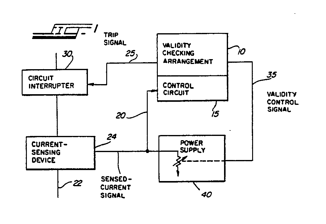
(57) An arrangement is provided for checking the validity of a sensed-current signal (at
20) from a current-sensing device (24). The sensed-current signal (at 20) represents
the current in a line (22). An associated control circuit (15,10) utilizes the sensed-current
signal (at 20) to indicate or predict the presence of undesired overcurrent conditions.
When such conditions may be present, the sensed-current signal (at 20) is checked
to determine if the sensed-current signal is valid; i.e., whether the sensed-current
signal (at 20) accurately represents the current in the line (22). If the sensed-current
signal is invalid, no trip signal (at 25) is generated to interrupt the current (via
30). If the sensed-current signal (at 20) is valid, the control circuit (15,10) generates
a trip signal (at 25) to control operation of a circuit-interrupting device (30).
In a particular arrangement, the load on the current-sensing device (24) is changed
(via 35,40) to determine if the sensed-current signal is valid. If the sensed-current
signal (at 20) is valid, the level of the sensed-current signal remains in a valid
range and the control circuit issues the trip signal (at 25). If the sensed-current
signal is invalid, the level of the sensed-current signal changes. In response, the
control circuit (15,10) does not issue the trip signal (at 25) and is reset to an
initialized mode to monitor for a valid overcurrent condition in response to the sensed-current
signal. In a specific arrangement, the current-sensing device is an iron-core transformer
which saturates at high current levels.
|
|
