| (19) |
 |
|
(11) |
EP 0 423 090 A1 |
| (12) |
EUROPEAN PATENT APPLICATION |
| (43) |
Date of publication: |
|
17.04.1991 Bulletin 1991/16 |
| (22) |
Date of filing: 25.09.1990 |
|
| (51) |
International Patent Classification (IPC)5: F15B 1/047 |
|
| (84) |
Designated Contracting States: |
|
AT BE CH DE DK ES FR GB GR IT LI LU NL |
| (30) |
Priority: |
09.10.1989 SE 8903310
|
| (71) |
Applicant: AKTIEBOLAGET ELECTROLUX |
|
S-105 45 Stockholm (SE) |
|
| (72) |
Inventors: |
|
- Fonser, Per-Ake
S-115 23 Stockholm (SE)
- Hagqvist, Peter Henning
S-125 30 Älvsjö (SE)
|
| (74) |
Representative: Erixon, Bo et al |
|
c/o AB ELECTROLUX Corporate Patents & Trademarks
105 45 Stockholm
105 45 Stockholm (SE) |
|
| |
|
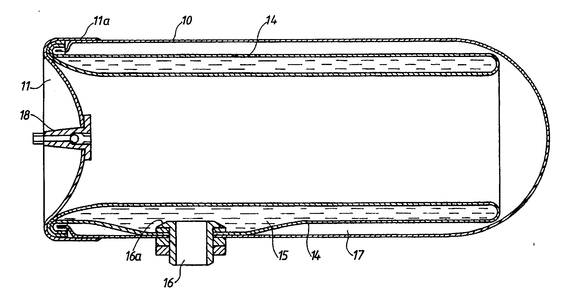
(57) A liquid accumulator comprises a generally cylindrical receptacle (10) having a flexible
membrane (14) dividing the interior of the receptacle into a liquid chamber (15) and
a gas chamber (17). The membrane comprises a hose which is open at both ends, one
of which is bent inwards and conveyed through the hose and the ends of the hose are
interconnected to form outer and inner membrane walls between which said liquid chamber
is enclosed.
|
|
[0001] The present invention relates to a liquid accumulator comprising a generally cylindrical
receptacle and a flexible membrane dividing the interior of the receptacle into a
liquid chamber and a gas chamber, said liquid chamber being completely enclosed by
said membrane and adapted to be connected to a conduit via a connection provided in
the wall of the receptacle.
[0002] In previously known accumulators of this kind both the chambers separated by the
membrane are defined by the membrane and the inner wall of the receptacle. In case
the liquid is water or any other corrosive liquid, the receptacle must either be made
of a stainless material or be subjected to an anti-corrosive treatment on its inside,
and the receptacle is therefore relatively expensive to manufacture. In addition,
the membrane is in certain stages exposed to considerable tension. Such a liquid
accumulator is disclosed in e.g. U.S. 2,919,718.
[0003] The object of the invention is to provide an accumulator for liquids in which the
above-mentioned disadvantages of the prior art have been eliminated. This object has
been achieved by means of a liquid accumulator of the kind mentioned in the introduction
which according to the invention is characterized in that the membrane is formed by
a hose which is open at both ends, one of said ends being bent inwards and conveyed
through the hose and the ends of the hose being interconnected to form outer and inner
membrane walls between which said liquid chamber is enclosed.
[0004] The invention will be described in more detail in the following with reference to
the accompanying drawing which illustrates a section of a preferred embodiment of
the liquid accumulator according to the invention.
[0005] The liquid accumulator shown in the drawing comprises a cylindrical receptacle 10
having an open end which is covered by an end wall 11. Inside the receptacle 10 is
provided a membrane 14 formed by a rubber hose which is open at both ends, and one
end has been folded inwards and conveyed through the hose to form an outer and an
inner membrane wall, as can been seen in the Figure. Both ends of the hose are bent
around the edge of the open end of the receptacle and clamped between this and the
end wall 11 which has a collar 11a bent around the end of the receptacle. The end
portions of the hose thus function as sealing members between the receptacle 10 and
the end wall 11 which is attached to the receptacle by means of suitable fastening
means (not shown).
[0006] The membrane 14 confines an annular chamber 15 which is intended for containing liquid
and is connected by means of a tube socket 16 to a conduit (not shown). The tube socket
16 extends through an opening in the wall of the receptacle 10 and the outer wall
of the membrane 14 and has an inner collar 16a by which the membrane is clamped against
the inside of the receptacle to provide a fluid-tight connection. The remaining portion
of the interior of the receptacle which is separated from the liquid chamber 15 forms
a gas chamber 17 containing an enclosed amount of e.g. air, the pressure of which
balancing the pressure in the liquid chamber 15. The end wall 11 is provided with
a valve 18 enabling adjustment of the pressure in the chamber 17.
[0007] Owing to the fact that the liquid chamber 15 is completely enclosed by the membrane
14, the inside of the receptacle will never be in contact with the liquid but only
with the enclosed gas which has no corrosive effect on the receptacle. As a consequence
thereof the receptacle can be made of inexpensive steel sheet which will need no
anti-corrosive treatment. As is easily realized, this results in a considerable reduction
of the manufacturing cost of the liquid accumulator.
[0008] As the membrane 14 is supported on its outside by the wall of the receptacle 10,
the liquid chamber 15 will mostly expand inwards when liquid is supplied. The membrane
will therefore not be subjected to any essential tension.
1. Liquid accumulator comprising a generally cylindrical receptacle (10) and a flexible
membrane (14) dividing the interior of the receptacle into a liquid chamber (15) and
a gas chamber (17), said liquid chamber being completely enclosed by said membrane
and adapted to be connected to a conduit via a connection (16) provided in the wall
of the receptacle, characterized in that the membrane (14) is formed by a hose which is open at both ends, one of
said ends being bent inwards and conveyed through the hose and the ends of the hose
being interconnected to form outer and inner membrane walls between which said liquid
chamber is enclosed.
2. Liquid accumulator according to claim 1, characterized in that the receptacle (10) comprises an end wall (11) removably attached to the
receptacle with the end portions of the hose sealingly clamped therebetween.