(57) Disclosed is an optical head of small size and light weight flying to float relative
to a signal recording and reproducing surface (18) of an optical disk (1), thereby
recording and reproducing an information signal on and from the signal recording and
reproducing surface (18) of the optical disk (1) with a high density by focusing a
laser beam by using an objective lens (21, 31) having a large numerical aperture NA.
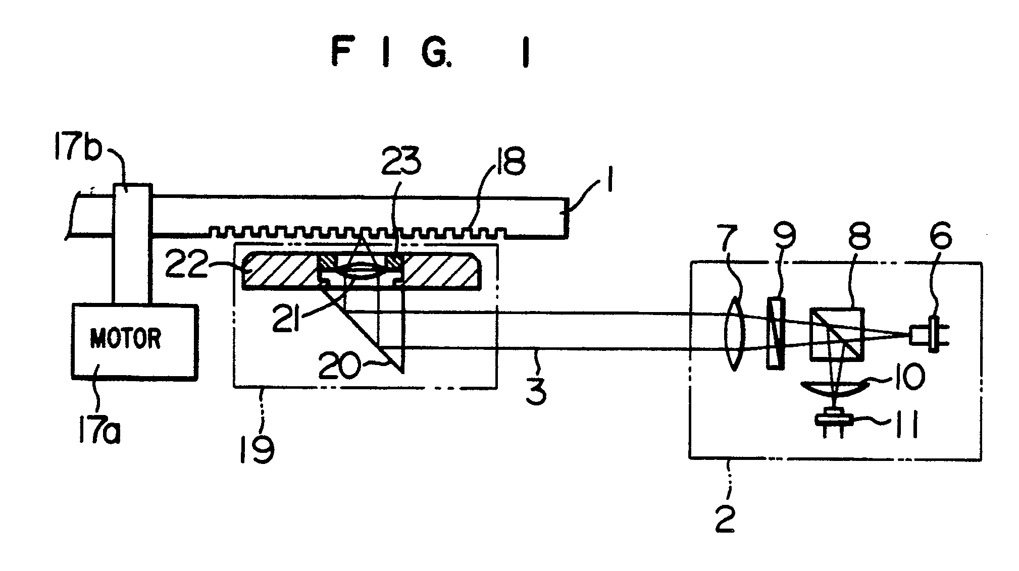
Disclosed also is an optical information recording and reproducing apparatus using
the optical head for information signal recording and reproduction. The optical head
comprises a fixed optical part (2) including a laser beam source (6), a collimation
lens (7), a reflected beam splitter (8) and a photo detector (11), a moving optical
part (19) including a beam reflector (20), an objective lens (21, 31) and a slider
(22) mounting the beam reflector (20) and the objective lens (21) thereon and flying
to float the objective lens relative to a signal recording and reproducing surface
(18) of an optical disk (1), and an actuating element (23, 32, 28, 35) mounted on
either the objective lens (21, 31) or the collimation lens (7), or an actuating element
(26) for driving a flexure (24) connecting the slider (22) to a linear motor (25),
or a lens part (40) for changing the position of the beam emission point of the
laser beam source (6). The slider (22) mounting the objective lens (21, 31) thereon
flies to float the objective lens (21, 31) relative to the signal recording and reproducing
surface (18) of the optical disk (1) through a gaseous layer, and fluctuation of the
flying height of the slider (22) is limited to a value smaller than about several
um substantially independently of vertical runout of the signal recording and reproducing
surface (18) of the optical disk (1), so that the movable distance of the objective
lens (21, 31) required for the focus control can be mimized. Therefore, the laser
beam can be focused into a diffraction-limited beam spot by using the objective lens
(21, 31) having a large numerical aperture NA, so that the optical head of the small
size and light weight can detect a substantially offsetless servo error signal. Thus,
a large-capacity memory device having a stacked structure permitting high-speed track
access can be provided.
|
|
