|
(11) | EP 0 323 662 B1 |

| (12) | EUROPEAN PATENT SPECIFICATION |
|
|
| (54) |
Moving target indication unit Anzeigegerät für bewegte Ziele Dispositif d'indication de cibles mobiles |
|
|
|||||||||||||||||||||||||||
| Note: Within nine months from the publication of the mention of the grant of the European patent, any person may give notice to the European Patent Office of opposition to the European patent granted. Notice of opposition shall be filed in a written reasoned statement. It shall not be deemed to have been filed until the opposition fee has been paid. (Art. 99(1) European Patent Convention). |
[0001] The present invention relates to a moving target indication unit provided with a doppler filter bank having n output channels Ai, i = 0, ..., n-1, with n threshold circuits connected thereto, and determination and registration means for setting the threshold circuit connected to each output channel per azimuth cell on the basis of received echo signals from the output channels of the doppler filter bank.
[0002] Such a system is known from FR-A 2.410.286. In this known system threshold values are calculated by comparing echo signals of an output channel with the echo signals of at least one other output channel to measure disturbing components and suppressing the disturbing component in the output channel, and performing an approximate decorrelation by forming submatrices symmetrical with the principal diagonal from the power spectrum matrix in a suboptimal detection technique suitable for real-time operation.
[0003] The system has as a disadvantage that considerable computer power is needed. The system according to the present invention obviates this disadvantage and is characterised in that said determination and registration means comprise memory means adapted to store k clutter maps, where 2 ≦ k ≦ n, for the registration per azimuth cell of k clutter-representing parameters, and determination means for the combined processing of said k parameters to obtain n threshold values.
[0004] The use of a clutter map is known from "Introduction to Radar Systems"; 2nd Edition, Merill I. Skolnik, Mc.Graw-Hill, 1981, pp. 127-129. In the system described the output signal of filter channel O, the channel with Doppler speeds of around 0 Hz, is used to estimate a parameter of the amount of clutter in an azimuth cell. This value is subsequently registered in a memory. To obtain a parameter for the amount of clutter in the remaining filter channels, a fixed functional connection is assumed between, on the one hand, the amount of clutter in output channel O and, on the other hand, the amount of clutter in the remaining channels.
[0005] In other words, a distribution of the clutter across the different channels is assumed. This implies that an estimation is made of the amount of clutter in the filter channels Ai (i = 1, 2, ..., n-1). It has been proven in practice that clutter suppression is not always effective. The inventor found that this is caused by the fact that the clutter distribution across the different output channels Ai is dependent on the type of clutter confronted. Different types of clutter occur especially in the case of search radars, where the radar covers different types of territories, e.g. land and sea clutter. Different types of clutter also occur as a result of variable weather conditions (anaprop).
[0006] Because, according to the invention, for k filter channels Ai with k ≧ 2 the amount of clutter is determined, it is possible to obtain a better impression of the changing functional relationships as regards the distribution of the amount of clutter across various output channels. To determine the k parameters bi belonging to the k filter channels Ai concerned, a parallel circuit of k known clutter analysis units can be used.
[0008] Because for each filter channel the amount of clutter per azimuth cell is determined, the threshold circuit belonging to the filter channel can be optimally adjusted without assuming a functional relationship indicating the distribution of clutter across the various filter channels.
[0009] An advantageous embodiment of the MTI-unit according to the invention is characterised in that the means for determination and registration of the parameters bi and bi+2 based on the output signals Ui and Ui+2 of output channels Ai and Ai+2, for obtaining threshold values Bi and Bi+2 based on the said parameters bi and bi+2 and for obtaining threshold values Bi+1 from parameters bi and bi+2 by means of interpolation.
[0010] Due to the application of interpolation, the memory capacity of the MTI unit can be limited to allow a cheaper construction of the MTI unit. It has been proven, that assuming a properly chosen form of interpolation, the performance is only slightly deteriorated.
[0011] An especially effective MTI unit can be applied in a radar apparatus with p different p.r.f.'s, where the means mentioned are suitable for determination and registration of the said parameters per azimuth cell and per p.r.f., and for setting the said threshold circuits per azimuth cell and per p.r.f. used.
[0012] By means of the interpolation methods described above, however, the number of clutter maps can be reduced. The combination of staggering on the one hand and interpolation on the other hand shows a combined result, allowing a particularly effective clutter suppression, while multiple-time-around echoes can be suppressed.
[0013] The invention will be further explained with reference to the following figures, of which
- Fig. 1
- shows a first possible embodiment of an MTI unit according to the invention;
- Fig. 2
- shows a division of the range of a radar apparatus into azimuth cells;
- Fig. 3
- shows a first embodiment of the clutter analysis unit of Fig. 1;
- Fig. 4
- shows an embodiment of the log-modulus unit operating on a time-sharing basis and the clutter analysis unit of fig. 1;
- Fig. 5
- shows a cost-effective embodiment of an MTI unit according to the invention.
[0014] Fig. 1 illustrates a doppler filter bank 1 with 16 output channels Ai (i = 0, 1, ..., 15) (n = 16).
[0015] The output signals of filter bank 1 in this embodiment consist in echo signals from a pulse doppler surveillance radar. These echo signals have after reception been transformed to an intermediate frequency. The doppler frequencies of the echo signals transformed to intermediate frequency are analysed in frequency by means of doppler filter bank 1. In practice, it is possible that the echo signals, before being supplied to the doppler filter, are digitised by means of an A/D converter, enabling the application of a 16-point FFT for the doppler filter bank. However, this does not exclude application of an analogue 16-point doppler filter. Filter channel A₀ embodies a zero-velocity filter. The sixteen output signals Ui (i = 0, 1, ..., 15) of the doppler filter bank are supplied via lines 2.i (i = 0, 1, ..., 15) respectively to log-modulus units 3.i (i = 0, 1, ..., 15). It is also possible to implement units 3.i for generation of the modulus square or the modulus of the input signal. The area covered by the search radar is illustrated in fig. 2. The area has been divided into a number of azimuth cells, one of which is azimuth cell 4.
[0016] For the embodiment in question it is assumed that the pulse repetition frequency of the search radar apparatus into which the MTI-unit has been implemented is 400 Hz, while a complete revolution is made in 6 sec. The radar apparatus therefore generates 2400 transmitter pulses in one revolution. The 16-point FFT sweeps are executed with a mutual overlap of twelve radar sweeps, i.e. two subsequent FFT sweeps cover an azimuth angle corresponding with the azimuth angle covered by four transmitter pulses. However, one azimuth cell covers 1.4° (one revolution comprises 256 azimuth cells), so one azimuth cell comprises two or three FFT sweeps.
[0017] For each azimuth cell the frequency spectrum is determined by means of doppler filterbank 1. Output signals Ui′ (i = 0, 1, ..., 15) of the log-modulus units 3.i (i = 0, ..., 15) belonging to an azimuth cell, are supplied via lines 5.i and 6.i (i = 0, ..., 15) to a clutter analysis unit 7. Clutter analysis unit 7 determines per cell for each output channel Ai a parameter bi (i = 0, 1, ..., 15) representing the maximum amount of clutter.
[0018] Fig. 3 illustrates a possible embodiment of clutter analysis unit 7. The clutter analysis unit consists of sixteen parallel-connected and identical maximum detectors 8.i (i = 0, ..., 15). A maximum detector 8.i is provided with a comparator 9.i and a register 10.i. At the start of each azimuth cell register 10.i is reset to zero. Signal Ui′ belonging to an azimuth cell is supplied to comparator 9.i via line 6.i. Comparator 9.i also receives the parameter bi, already stored in register 10.i, via line 11.i. If Ui′ ≧ bi, the comparator switches a switching unit 12.i to position I, causing bi to be overwritten with the value of Ui′. In case Ui′ < bi, comparator 9.i sets switching unit 12.i to position II, causing the original value of bi to be written into register 10.i again. In this way, the maximum value of
is selected from the subsequent signals Ui belonging to the subsequent FFT sweeps of one azimuth cell. The sixteen parameters bi are supplied to a filter unit 14 via lines 13.i (i = 0, ..., 15) for each azimuth cell. For the filter unit, median, mean or top(modulus) filters may be applied. For mean filters, linear filters qualify, such as low-pass filters, FIR filters or recursive filters. A top filter determines the maximum value of a frequency distribution. In this case the use of low-pass filters is further described. Low-pass unit 14 is in this configuration provided with sixteen parallel-connected and identical low-pass filters 15.i (i = 0, ..., 15). The sixteen output signals of low-pass unit 14 are stored in a memory 18 via lines 17.i (i = 0, ..., 15). Low-pass unit 14 also receives, via lines 16.i (i = 0, ..., 15), the parameters bi of an azimuth cell already stored in memory 18. The transfer of a low-pass filter 15.i can be described as follows:
where 0 < γ < 1.
[0019] In this formula,
is the old parameter bi, obtained during a preceding revolution, stored in the memory and supplied via line 16.i, bi is a parameter of an azimuth cell determined by clutter analysis unit 7 and supplied via line 13.i, and
is the parameter supplied via line 17.i with which the parameter
is overwritten in the memory.
[0020] It will be clear that it is possible to replace on a time-sharing basis the clutter analysis unit and the log-modulus units 3.i with one comparator 9.i, register 10.i and a log-modulus unit 3.i (see Fig. 4). For this purpose, two switching means 20 and 21 are implemented which ensure that signals bi (0, ..., 15) are processed and supplied by successively assuming positions 0 to 15. Thus the amount of clutter is recorded for each cell. In this way, a recording is made, as it were, of sixteen clutter maps of the area covered by the search radar: one clutter map for each output channel of the doppler filter. When the search radar covers an azimuth cell of the environment, the accompanying parameters
(hereafter called bi) are read from the memory and supplied to a threshold value unit 23 via lines 22.i (i = 0, ..., 15). Threshold value unit 23 for each parameter bi generates an accompanying signal Bi (i = 0, ..., 15), which is used to set the threshold level of the sixteen threshold circuits 24.i (i = 0, ..., 15) respectively via lines 25.i (i = 0, ..., 15). The output signals Ui′ of the log-modulus unit 3.i are supplied to threshold circuit 24.i via lines 5.i (i = 0, ..., 15). If output signals Ai of a log-modulus unit 3.i exceed the accompanying threshold value Bi, this signal is supplied for further processing via the accompanying threshold circuits 24.i to lines 26.i (i = 0, ..., 15). Because for each output signal the accompanying clutter map is recorded in the memory, optimal clutter suppression is realised.
[0021] An especially cost-effective embodiment is illustrated in Fig. 5. In this embodiment, only the eight output signals Ui′ of log-modulus units 3.i (i = 0, 2, 4, ..., 14) are supplied to clutter analysis unit 7. Eight clutter maps are therefore stored in the memory, belonging to the output signals of logmodulus units 3.i (i = 0, 2, 4, ..., 14). When the radar apparatus covers an azimuth cell of Fig. 2, the eight accompanying parameters bi (i = 0, 2, 4, ..., 14) are supplied to threshold value unit 23 via lines 22.i (i = 0, 2, 4, ..., 14). Threshold value unit 23 generates eight threshold value signals Bi (i - 0, 2, ..., 14) from parameters bi (i = 0, 2, ..., 14).
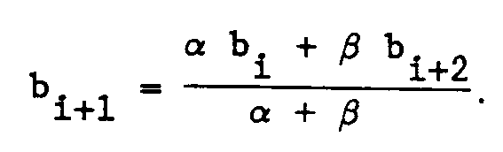
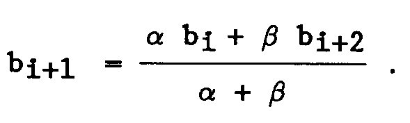
[0022] Threshold values Bi (i = 1, 3, ..., 15) are obtained through interpolation. For this purpose, threshold value unit 23 is provided with means for the execution of the following calculation:
where i = 0, 2, ..., 14, where
.
[0023] From the values bi (i = 1, 3, ..., 15) obtained through interpolation, threshold value unit 23 generates threshold value signals Bi (i = 1, 3, ..., 15), which are supplied to threshold circuits 24.i (i = 1, 3, ..., 15) via lines 25.i (i = 1, 3, ..., 15) respectively.
[0024] The MTI unit is provided with a timing generator 27 for generating signals Ŝ to control the MTI unit in time.
[0025] It will be clear that according to the invention other interpolation methods can be used as well. It is also possible to further reduce the number of clutter maps. Thus, it has been shown that an especially effective clutter suppression is only obtained if clutter maps are compiled for output channels Ai (i = 0, 2, 4, 8, 12, 14). For output channels Ai (i = 6, 7, 9, 10), the threshold unit uses the clutter map belonging to output channel A₈, while for the other channels Ai (i = 1, 3, 5, 11, 13, 15), the above-described interpolation between two neighbouring output channels is applied.
[0026] If the radar apparatus in which the above-described MTI unit is applied, uses a staggered pulse repetition frequency (two or more p.r.f.'s), it is possible to record a set of clutter maps as described above for the pulse repetition frequencies. The number of clutter maps will then double in case staggering implies the use of two p.r.f.'s. Staggering is important for the suppression of multiple-time-around echoes, because they take up different positions for the different p.r.f.'s. If for staggering p different p.r.f.'s are used, the number of clutter maps will be increased by a factor p.
[0027] By means of the above-described interpolation methods, the number of clutter maps can however be decreased again. The combination of staggering on the one hand and interpolation on the other hand has the combined result of allowing a specially effective clutter suppression while suppressing multiple-time-around echoes.
1. Moving target indication unit provided with a doppler filter bank (1) having n output
channels Ai, i = 0, ..., n-1, with n threshold circuits (24.i) connected thereto, and determination
and registration means (7,14,18,23) for setting the threshold circuit (24.i) connected
to each output channel per azimuth cell on the basis of received echo signals from
the output channels of the doppler filter bank (1), characterised in that said determination
and registration means comprise memory means (18) adapted to store k clutter maps,
where 2 ≦ k ≦ n, for the registration per azimuth cell of k clutter-representing parameters
(bi), and determination means (23) for the combined processing of said k parameters to
obtain n threshold values (25.i).
2. Moving target indication unit as claimed in claim 1, characterised in that
.
.
3. Moving target indication unit as claimed in claim 1, characterised in that the said
determination means (23) are suitable for the execution of an interpolation of k parameters
(bi) to obtain n threshold values (25.i).
4. Moving target indication unit as claimed in claim 3, characterised in that the said
determination and registration means (7,14,18,23) are suitable for the determination
and registration of parameters bi and bi+2 based on the output signals Ui and Ui+2 of output channels Ai and Ai+2, for obtaining threshold values Bi and Bi+2 based on the said parameters bi and bi+2 and for obtaining threshold values Bi+1 from parameters bi and bi+2 by means of interpolation.
5. Moving target indication unit as claimed in claim 4, characterised in that the said
determination means (23) are suitable for calculating bi+1, i = 0, 2, ..., n-2, according to the method
6. Moving target indication unit as claimed in one of the above claims, characterised
in that the said determination and registration means (7,14,18,23) are provided with
a filter unit (14) for combined processing of a parameter bi already stored in one of the clutter maps (18) and a newly determined output signal
Ui to obtain a new parameter bi with which the old parameter bi is overwritten.
7. A radar apparatus with p different p.r.f.'s comprising the moving target indication
unit as claimed in one of the above claims, characterised in that the said determination
and registration means are suitable for determination and registration of the said
parameters per azimuth cell and per p.r.f. and for setting the said threshold circuits
(24.i) per azimuth cell and per p.r.f. used.
8. A radar apparatus as claimed in claim 7, characterised in that
.
.
9. A radar apparatus as claimed in claim 7, characterised in that
.
.
1. Anzeigegerät für bewegte Ziele, versehen mit einer Doppler-Filterbank (1) mit n Ausgangskanälen
Ai, i = 0, ..., n-1, mit n damit verbundenen Schwellenschaltkreisen (24.i), und Ermittlungs-
und Aufzeichnungsmitteln (7, 14, 18, 23) zur Einstellung der Schwellenschaltkreise
(24.i), verbunden mit jedem Ausgangskanal pro Azimutzelle auf Basis von empfangenen
Echosignalen von den Ausgangskanälen der Doppler-Filterbank (1), dadurch gekennzeichnet,
daß die erwähnten Ermittlungs- und Aufzeichnungsmittel Speichermittel (18) umfassen,
welche Speichermittel zur Speicherung von k Clutter-Karten eingerichtet sind, wobei
2 ≦ k ≦ n, für die Aufzeichnung pro Azimutzelle von k clutter-repräsentierenden Parametern
(bi), und die Ermittlungsmittel (23) zur kombinierten Verarbeitung der erwähnten k Parameter
eingerichtet sind, zum Erhalt von n Schwellenwerten (25.i).
2. Anzeigegerät für bewegte Ziele gemäß Anspruch 1, dadurch gekennzeichnet, daß
.
.
3. Anzeigegerät für bewegte Ziele gemäß Anspruch 1, dadurch gekennzeichnet, daß die erwähnten
Ermittlungsmittel (23) zur Duchführung einer Interpolation von k Parametern (bi) eingerichtet sind, zum Erhalt von n Schwellenwerten (25.i).
4. Anzeigegerät für bewegte Ziele gemäß Anspruch 3, dadurch gekennzeichnet, daß die erwähnten
Ermittlungs- und Aufzeichnungsmittel (7, 14, 18, 23) zur Ermittlung und Aufzeichnung
der Parameter bi und bi+2 eingerichtet sind, welche Parameter auf den Ausgangssignalen Ui und Ui+2 der Ausgangskanäle Ai und Ai+2 basieren, zum Erhalt der Schwellenwerte Bi und Bi+2, welche Schwellenwerte auf den erwähnten Parametern bi und bi+2 basieren, und zum Erhalt der Schwellenwerte Bi+1 aus den Parametern bi und bi+2 mit Hilfe von Interpolation.
5. Anzeigegerät für bewegte Ziele gemäß Anspruch 4, dadurch gekennzeichnet, daß die erwähnten
Ermittlungsmittel (23) eingerichtet sind zur Berechnung bi+1, i = 0, 2, ..., n-2 gemäß der Methode
6. Anzeigegerät für bewegte Ziele gemäß einem der vorangehenden Ansprüche, dadurch gekennzeichnet,
daß die erwähnten Ermittlungs- und Aufzeichnungsmittel (7, 14, 18, 23) mit einer Filtereinheit
(14) versehen sind, zur kombinierten Verarbeitung eines bereits in einem der Clutter-Karten
(18) gespeicherten Parameters bi und eines neu ermittelten Ausganssignals Ui, zum Erhalt eines neuen Parameters bi, mit dem der alte Parameter bi überschrieben wird.
7. Ein Radargerät mit p unterschiedlichen PRFs, das das Anzeigegerät für bewegte Ziele
gemäß einem der vorangehenden Ansprüche umfaßt, dadurch gekennzeichnet, daß die erwähnten
Ermittlungs- und Aufzeichnungsmittel zur Ermittlung und Aufzeichnung der erwähnten
Parameter pro Azimutzelle und pro PRF sowie zur Einstellung der erwähnten Schwellenschaltkreise
(24.i) pro angewendete Azimutzelle und PRF eingerichtet sind.
8. Ein Radargerät gemäß Anspruch 7, dadurch gekennzeichnet, daß
.
.
9. Ein Radargerät gemäß Anspruch 7, dadurch gekennzeichnet, daß
.
.
1. Unité d'indication de cible mobile comportant un banc (1) de filtres Doppler comportant
n canaux de sortie Ai, i = 0, ..., n-1, avec n circuits de seuil (24.i) qui leur sont connectés, et des
moyens de détermination et d'enregistrement (7, 14, 18, 23) pour régler le circuit
de seuil (24.i) connecté à chaque canal de sortie par cellule d'azimut sur la base
des signaux d'écho reçus des canaux de sortie du banc (1) de filtres Doppler, caractérisée
en ce que lesdits moyens de détermination et d'enregistrement comportent des moyens
mémoire (18) adaptés à stocker k cartes de bruit de clutter, où 2 ≦ k ≦ n, pour l'enregistrement
par cellule d'azimut de k paramètres (bi) de représentation du bruit de clutter, et des moyens de détermination (23) pour
le traitement combiné desdits k paramètres pour obtenir n valeurs de seuil (25.i).
2. Unité d'indication de cible mobile selon la revendication 1, caractérisée en ce que
.
.
3. Unité d'indication de cible mobile selon la revendication 1, caractérisée en ce que
lesdits moyens de détermination (23) sont adaptés à l'exécution d'une interpolation
de k paramètres (bi) pour obtenir n valeurs de seuil (25.i).
4. Unité d'indication de cible mobile selon la revendication 3, caractérisée en ce que
lesdits moyens de détermination et d'enregistrement (7, 14, 18, 23) sont adaptés à
la détermination et à l'enregistrement de paramètres bi et bi+2 sur la base de signaux de sortie Ui et Ui+2 de canaux de sortie Ai et Ai+2, pour obtenir des valeurs de seuil Bi et Bi+2 sur la base desdits paramètres bi et bi+2 et pour obtenir des valeurs de seuil Bi+1 de paramètres bi et bi+2 au moyen d'une interpolation.
5. Unité d'indication de cible mobile selon la revendication 4, caractérisée en ce que
lesdits moyens de détermination (23) sont adaptés à calculer bi+1, i = 0, 2, ..., n-2, selon la formule :

.
.
6. Unité d'indication de cible mobile selon l'une des revendications précédentes, caractérisée
en ce que lesdits moyens de détermination et d'enregistrement (7, 14, 18, 23) sont
munis d'une unité de filtre (14) pour un traitement combiné d'un paramètre bi déjà stocké dans l'une des cartes de bruit de clutter (18) et d'un signal de sortie
Ui nouvellement déterminé pour obtenir un nouveau paramètre bi avec lequel l'ancien paramètre bi est surimprimé.
7. Appareil radar avec différents p de p. r. f. comprenant l'unité d'indication de cible
mobile revendiquée selon l'une des revendications précédentes, caractérisé en ce que
lesdits moyens de détermination et d'enregistrement sont adaptés pour déterminer et
enregistrer lesdits paramètres par cellule d'azimut et par p. r. f. et pour régler
lesdits circuits de seuil (24.i) par cellule d'azimut et par p. r. f. utilisé.
8. Appareil radar selon la revendication 7, caractérisé en ce que
.
.
9. Appareil radar selon la revendication 7, caractérisé en ce que
.
.