| (19) |
 |
|
(11) |
EP 0 348 164 B1 |
| (12) |
EUROPEAN PATENT SPECIFICATION |
| (45) |
Mention of the grant of the patent: |
|
09.02.1994 Bulletin 1994/06 |
| (22) |
Date of filing: 20.06.1989 |
|
|
| (54) |
Sealing arrangement for a rotatable drum in a vat
Dichtungseinrichtung für eine in einer Wanne drehbaren Trommel
Dispositif d'étanchéité pour un tambour rotatif se trouvant dans une cuve
|
| (84) |
Designated Contracting States: |
|
AT DE ES FR GB SE |
| (30) |
Priority: |
22.06.1988 US 209597
|
| (43) |
Date of publication of application: |
|
27.12.1989 Bulletin 1989/52 |
| (73) |
Proprietor: INGERSOLL-RAND COMPANY |
|
Woodcliff Lake
New Jersey 07675-8738 (US) |
|
| (72) |
Inventor: |
|
- Bardsley, Donald E.
Nashua
New Hampshire 03063 (US)
|
| (74) |
Representative: Lightfoot, Robert Oscar et al |
|
Raworth, Moss & Cook
36 Sydenham Road
Croydon
Surrey, CR0 2EF
Croydon
Surrey, CR0 2EF (GB) |
| (56) |
References cited: :
FR-A- 1 365 269
US-A- 2 894 635
|
GB-A- 625 898
US-A- 4 394 021
|
|
| |
|
|
|
|
| |
|
| Note: Within nine months from the publication of the mention of the grant of the European
patent, any person may give notice to the European Patent Office of opposition to
the European patent
granted. Notice of opposition shall be filed in a written reasoned statement. It shall
not be deemed to
have been filed until the opposition fee has been paid. (Art. 99(1) European Patent
Convention).
|
[0001] This invention relates to sealing arrangement for a rotatable drum in a vat, and
in particular to rotatable vacuum or pressure washer drums used for washing pulp in
pulp mills with a seal between the rotatable drum and an adjacent stationary member
to separate a particular area of the vat from another particular area.
[0002] Pneumatic and hydraulic seals are available today but lack certain qualities for
proper function. In addition, they normally seal in a unidirectional way, see e.g.
US-A-2894635.
[0003] The seal structure of this invention is a sealing arrangement between each end of
the rotatable drum and an adjacent stationary member of the vat. The sealing arrangement
has the unique property of sealing in a bi-directional way.
[0004] According to one aspect of the present invention, there is provided a rotatable drum
mounted in a vat, characterized by a circumferential, inflatable tube retainer at
each end of the rotatable drum extending at least partly around the circumference
of the rotatable drum and located between the end of the rotatable drum and the inside
surface of the vat; each circumferential, inflatable tube retainer having an inside
surface extending at an acute angle with respect to the axis of the rotatable drum;
a circumferential wear shoe with a generally triangular cross-section at each end
of the drum in sealing contact with the drum, along a first side of the wear shoe,
a second side of the wear shoe facing and substantially parallel to said inside surface
of the circumferential, inflatable tube retainer, said second side having a generally
semi-cylindrical groove extending along the length of the wear shoe; an inflatable
tube located in each wear shoe groove and in contact with said inflatable tube retainer
inside surface; and a wear shoe retainer having a surface in contact with the third
side of the wear shoe.
[0005] According to a second aspect of the present invention, there is provided a rotatable
inner drum mounted in an outer drum, characterized by a circumferential, inflatable
tube retainer at one end of the rotatable drum extending at least partly around the
circumference of the rotatable drum and located between the end of the rotatable drum
and the inside surface of the outer drum; the circumferential, inflatable tube retainer
having an inside surface extending at an acute angle with respect to the axis of the
rotatable drum; a circumferential wear shoe with a generally triangular cross-section
at said one end of the rotatable drum in sealing contact with the rotatable drum,
along a first side of the wear shoe, a second side of the wear shoe facing and substantially
parallel to said inside surface of the circumferential, inflatable tube retainer,
said second side having a generally semi-cylindrical groove extending along the length
of the wear shoe; an inflatable tube located in the wear shoe groove and in contact
with said inflatable tube retainer inside surface; and a wear shoe retainer having
a surface in contact with the third side of the wear shoe.
[0006] For a better understanding of the present invention, and to show how the same may
be carried into effect, reference will now be made, by way of example, to the accompanying
drawings, in which:-
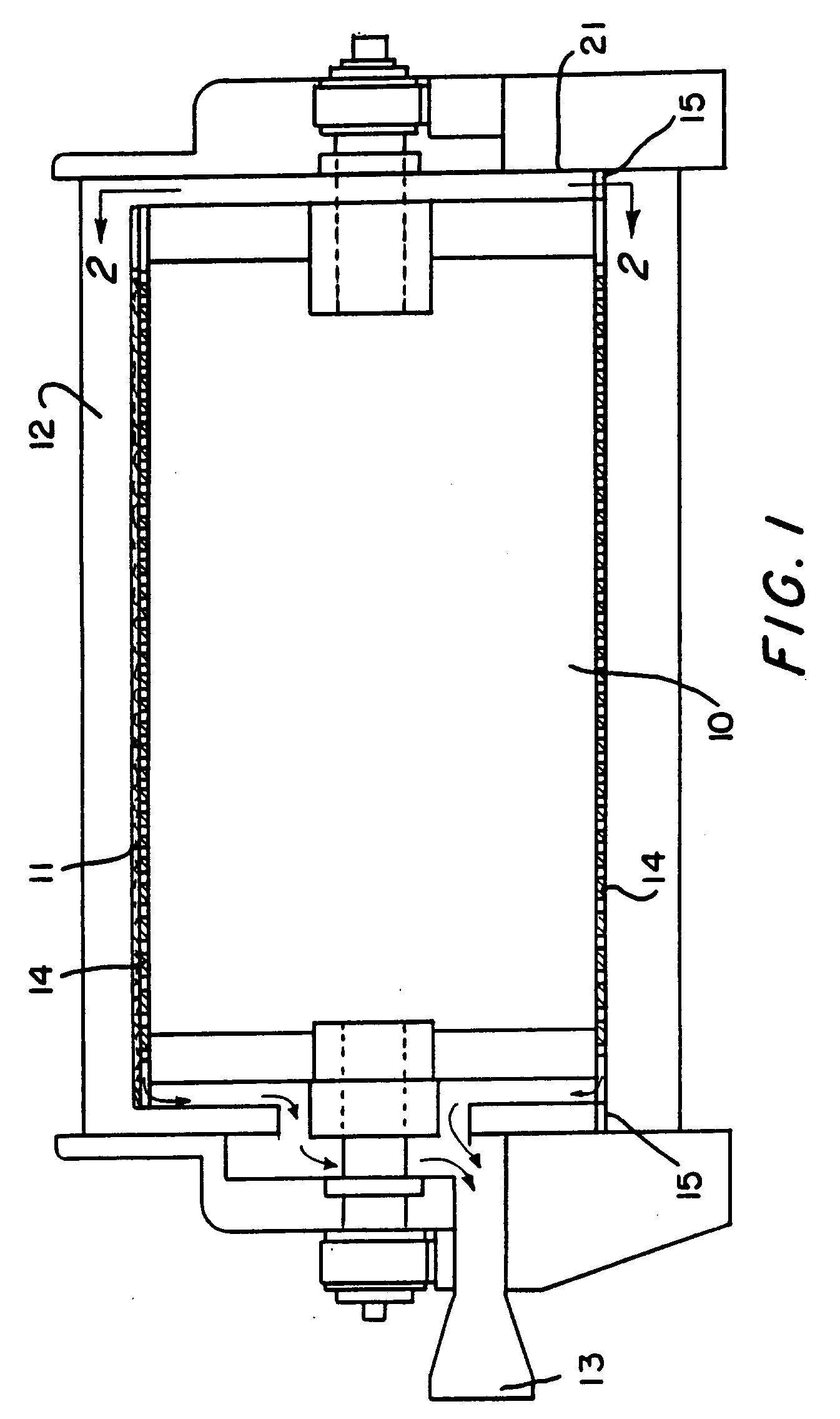
Figure 1 is a side elevational view, partly in section, showing the use of the new
seal in a vat used for the washing of pulp;
Figure 2 is a view taken along lines 2--2 of Figure 1 and in the direction of the
arrows and illustrating the circumferential positioning of the sealing arrangement;
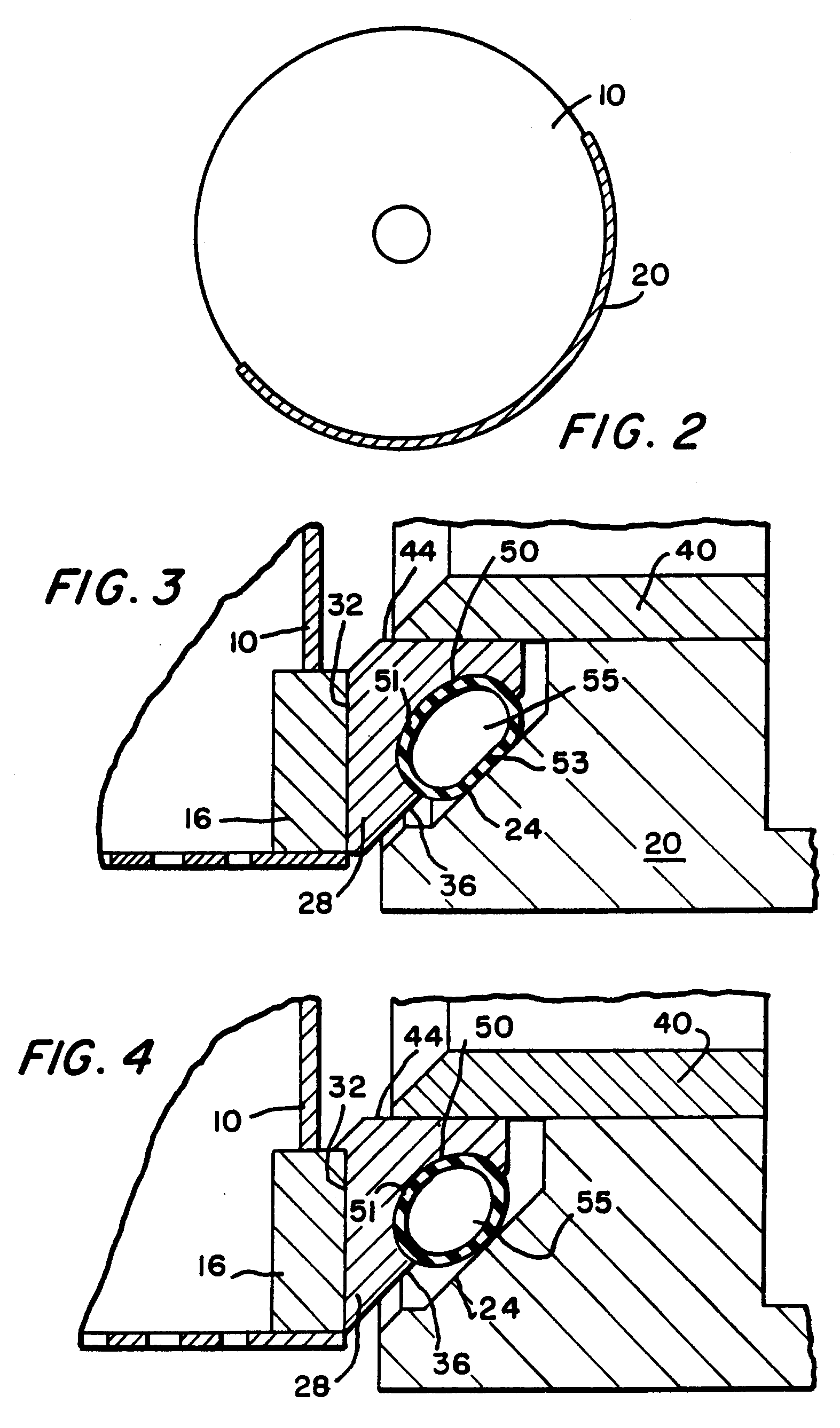
Figure 3 is an enlarged sectional view, showing the details of the sealing structure
of the embodiment of Figure 1 and Figures 2; and
Figure 4 is a view similar to Figure 3, but showing the change in dimensions of a
wear shoe and inflatable tube as the wear shoe wears;
In the various figures, like parts are referred to by like numbers.
[0007] Referring to the drawings and more particularly to Figure 1, a rotatable drum 10
is mounted for rotation within a vat 12. In operation, a pulp slurry is fed into the
vat. A differential pressure is applied across the drum by, for example, a vacuum
on the inside of the drum to form a pulp mat 11. Filtrate drawn into a screen or deck
14 flows from the drum through a filtrate outlet 13. A seal 15, (shown schematically),
is provided at each axial end of the drum. One seal will be described. It is to be
understood that the other seal has the same structure as the described seal.
[0008] As shown in Figure 3, the rotatable drum is provided with an end ring 16. An inflatable
tube retainer 20 for retaining an inflatable tube is connected to an end wall 21 of
the vat (see Figure 1). As can be seen from looking at Figure 2, the inflatable tube
retainer 20 which is fixed to the vat 12 extends approximately half-way around the
circumference of the drum 10. The retainer 20 has an inside surface 24 (see Figure
3), which extends at an acute angle with respect to the axis of the rotatable drum.
[0009] A wear shoe 28 is located adjacent the axial end of the rotatable drum 10. In the
embodiment shown, the wear shoe does not rotate and extends around approximately half
the circumference of the drum. The wear shoe is generally triangular in cross-section.
The side 32 of the wear shoe 28, is in sealing contact with the end ring 16, of the
rotatable drum 10. The side 36 of the wear shoe 28 faces the inside surface 24 of
the inflatable tube retainer 20 and is also parallel to the inside surface 24. The
wear shoe retainer 40, which keeps the wear shoe in place, contacts the surface 44
of the wear shoe 28.
[0010] The side 36 of the wear shoe 28 is provided with a generally semi-cylindrical groove
50. Located within the groove 50 is an inflatable tube 55. The pressure within the
inflatable tube keeps its outside surface in contact with the surface of groove 50
and the inside surface 24 of retainer 20. When first installed, the surface 51 in
contact with the groove 50 is arcuate and the side 53 in contact with the inside surface
24 of the inflatable tube retainer 20 is flat (see Figure 3).
[0011] The seal has particular use when it is desired to separate or exclude one particular
area of the vat from another particular area of the vat. For example, if the vat is
used for washing pulp, it is highly important that the pulp fibres do not get between
the end of the rotatable drum 10 and the end of the vat 12. Fibres between the end
of the drum and the vat would act like a brake. The pressure within the inflatable
tube causes a force to be directed against the end ring on the rotatable drum and
also against the bottom surface of the wear shoe retainer 40. Thus, the inflatable
seal has the unique property of applying a sealing force in a bi-directional way.
As the wear shoe wears, the inflatable seal will change from an approximate elliptical
installation configuration to a more circular configuration as shown in Figure 4 while
still maintaining a seal at all times.
1. A rotatable drum (10) mounted in a vat (12), characterized by a circumferential, inflatable
tube retainer (20) at each end of the rotatable drum (10) extending at least partly
around the circumference of the rotatable drum and located between the end of the
rotatable drum and the inside surface of the vat; each circumferential, inflatable
tube retainer (20) having an inside surface (24) extending at an acute angle with
respect to the axis of the rotatable drum; a circumferential wear shoe (28) with a
generally triangular cross-section at each end of the drum in sealing contact with
the drum (10), along a first side (32) of the wear shoe (28), a second side (36) of
the wear shoe facing and substantially parallel to said inside surface of the circumferential,
inflatable tube retainer (20), said second side (36) having a generally semi-cylindrical
groove (50) extending along the length of the wear shoe (28); an inflatable tube (51,
53) located in each wear shoe groove (50) and in contact with said inflatable tube
retainer inside surface (24); and a wear shoe retainer (40) having a surface in contact
with the third side of the wear shoe (28).
2. A rotatable inner drum (10) mounted in an outer drum (12), characterized by a circumferential,
inflatable tube retainer (20) at one end of the rotatable drum (10) extending at least
partly around the circumference of the rotatable drum and located between the end
of the rotatable drum and the inside surface of the outer drum; the circumferential,
inflatable tube retainer (20) having an inside surface (24) extending at an acute
angle with respect to the axis of the rotatable drum; a circumferential wear shoe
(28) with a generally triangular cross-section at said one end of the rotatable drum
in sealing contact with the rotatable drum (10), along a first side (32) of the wear
shoe (28), a second side (36) of the wear shoe facing and substantially parallel to
said inside surface of the circumferential, inflatable tube retainer (20), said second
side (36) having a generally semi-cylindrical groove (50) extending along the length
of the wear shoe (28); an inflatable tube (51, 53) located in the wear shoe groove
(50) and in contact with said inflatable tube retainer inside surface (24); and a
wear shoe retainer (40) having a surface in contact with the third side of the wear
shoe (28).
1. Drehbare Trommel (10), die in einer Wanne (12) gelagert ist, gekennzeichnet durch einen sich in Umfangsrichtung erstreckenden Halter (20) für einen aufblasbaren
Schlauch an jedem Ende der drehbaren Trommel (10), der sich wenigstens teilweise um
den Umfang der drehbaren Trommel herum erstreckt und zwischen dem Ende der drehbaren
Trommel und der inneren Oberfläche der Wanne angeordnet ist, wobei jeder sich in Umfangsrichtung
erstreckende Halter (20) für den aufblasbaren Schlauch eine innere Oberfläche (24)
hat, die sich unter einem spitzen Winkel in bezug auf die Achse der drehbaren Trommel
erstreckt, wobei ein sich in Umfangsrichtung erstreckender Verschleißschuh (28) mit
einem allgemein dreieckigen Querschnitt an jedem Ende der Trommel in Abdichtungsberührung
mit der Trommel (10) längs einer ersten Seite (32) des Verschleißschuhs (28) steht,
wobei eine zweite Seite (36) des Verschleißschuhs auf die innere Oberfläche des sich
in Umfangsrichtung erstreckenden Halters (20) für den aufblasbaren Schlauch zu weist
und im wesentlichen parallel zu dieser Oberfläche angeordnet ist, wobei die zweite
Seite (36) eine im wesentlichen halbzylindrische Nut (50) hat, die sich längs der
Länge des Verschleißschuhs (28) erstreckt, wobei ein aufblasbarer Schlauch (51, 53)
in jeder Nut (50) des Verschleißschuhs angeordnet ist und in Berührung mit der inneren
Oberfläche (24) des Halters für den aufblasbaren Schlauch steht, und wobei ein Halter
(40) für den Verschleißschuh eine Oberfläche hat, die in Berührung mit der dritten
Seite des Verschleißschuhs (28) steht.
2. Drehbare innere Trommel (10), die in einer äußeren Trommel (12) gelagert ist, gekennzeichnet durch einen sich in Umfangsrichtung erstreckenden Halter (20) für einen aufblasbaren
Schlauch an einem Ende der drehbaren Trommel (10), der sich wenigstens teilweise um
den Umfang der drehbaren Trommel herum erstreckt und zwischen dem Ende der drehbaren
Trommel und der inneren Oberfläche der äußeren Trommel angeordnet ist, wobei der sich
in Umfangsrichtung erstreckende Halter (20) für den aufblasbaren Schlauch eine innere
Oberfläche (24) hat, die sich unter einem spitzen Winkel in bezug auf die Achse der
drehbaren Trommel erstreckt, wobei ein sich in Umfangsrichtung erstreckender Verschleißschuh
(28) mit einem allgemein dreieckigen Querschnitt an dem einen Ende der drehbaren Trommel
in Abdichtungsberührung mit der drehbaren Trommel (10) längs einer ersten Seite (32)
des Verschleißschuhs (28) steht, wobei eine zweite Seite (36) des Verschleißschuhs
auf die innere Oberfläche des sich in Umfangsrichtung erstreckenden Halters (20) für
den aufblasbaren Schlauch zu weist und im wesentlichen parallel zu dieser Oberfläche
angeordnet ist, wobei die zweite Seite (36) eine im wesentlichen halbzylindrische
Nut (50) hat, die sich längs der Länge des Verschleißschuhs (28) erstreckt, wobei
ein aufblasbarer Schlauch (51, 53) in der Nut (50) des Verschleißschuhs angeordnet
ist und in Berührung mit der inneren Oberfläche (24) des Halters für den aufblasbaren
Schlauch steht, und wobei ein Halter (40) für den Verschleißschuh eine Oberfläche
hat, die in Berührung mit der dritten Seite des Verschleißschuhs (28) steht.
1. Tambour rotatif (10) monté dans une cuve (12), caractérisé par un dispositif circonférentiel
de retenue (20) de tube gonflable à chaque extrémité du tambour rotatif (10), qui
s'étend au moins partiellement autour de la circonférence du tambour rotatif et situé
entre l'extrémité du tambour rotatif et la surface intérieure de la cuve; en ce que
chaque dispositif circonférentiel de retenue (20) de tube gonflable présente une surface
intérieure (24) qui s'étend sous un angle aigu par rapport à l'axe du tambour rotatif;
en ce qu'il est prévu un sabot d'usure (28) circonférentiel de section transversale
généralement triangulaire à chaque extrémité du tambour en contact étanche contre
le tambour (10) le long d'un premier côté (32) du sabot d'usure (28), un second côté
(36) du sabot d'usure étant en regard et sensiblement parallèle à ladite surface intérieure
du dispositif circonférentiel de retenue (20) de tube gonflable, ledit second côté
(36) présentant une gorge (50) généralement semi-cylindrique qui s'étend le long de
la longueur du sabot d'usure (28); en ce qu'il est prévu un tube gonflable (51, 53)
situé dans la gorge (50) de chaque sabot d'usure et en contact avec la surface intérieure
(24) dudit dispositif de retenue de tube gonflable; et en ce qu'il est prévu un organe
de retenue (40) pour le sabot d'usure, qui présente une surface en contact avec le
troisième côté du sabot d'usure (28).
2. Tambour intérieur rotatif (10) monté dans un tambour extérieur (12), caractérise par
un dispositif circonférentiel de retenue (20) de tube gonflable à une extrémité du
tambour rotatif (10), qui s'étend au moins partiellement autour de la circonférence
du tambour rotatif, et est situé entre l'extrémité du tambour rotatif et la surface
intérieure du tambour extérieur; en ce que le dispositif circonférentiel de retenue
(20) de tube gonflable présente une surface intérieure (24) qui s'étend sous un angle
aigu par rapport à l'axe du tambour rotatif; en ce qu'il est prévu un sabot d'usure
(28) circonférentiel de section transversale généralement triangulaire à ladite extrémité
du tambour rotatif, en contact étanche contre le tambour rotatif (10) le long d'un
premier côté (32) du sabot d'usure (28), un second côté (36) du sabot d'usure étant
en regard et sensiblement parallèle à ladite surface intérieure du dispositif circonférentiel
de retenue (20) de tube gonflable, ledit second côté (36) présentant une gorge (50)
généralement semicylindrique qui s'étend le long de la longueur du sabot d'usure (28);
en ce qu'il est prévu un tube gonflable (51, 53) situé dans la gorge (50) du sabot
d'usure et en contact avec la surface intérieure (24) dudit dispositif de retenue
de tube gonflable; et en ce qu'il est prévu un organe de retenue (40) pour le sabot
d'usure, qui présente une surface en contact avec le troisième côté du sabot d'usure
(28).