| (19) |
 |
|
(11) |
EP 0 422 660 B1 |
| (12) |
EUROPEAN PATENT SPECIFICATION |
| (45) |
Mention of the grant of the patent: |
|
09.02.1994 Bulletin 1994/06 |
| (22) |
Date of filing: 11.10.1990 |
|
| (51) |
International Patent Classification (IPC)5: A61F 13/20 |
|
| (54) |
Tampon, especially for feminine hygiene, and a process and apparatus for producing
this
Tampon, insbesondere für die weibliche Hygiene, Verfahren und Vorrichtung für dessen
Herstellung
Tampon particulièrement pour l'hygiène féminine et un procédé et dispositif pour sa
production
|
| (84) |
Designated Contracting States: |
|
AT BE CH DE DK ES FR GB IT LI LU NL SE |
| (30) |
Priority: |
12.10.1989 DE 3934153
|
| (43) |
Date of publication of application: |
|
17.04.1991 Bulletin 1991/16 |
| (73) |
Proprietor: McNEIL-PPC, INC. |
|
Milltown
New Jersey 08850 (US) |
|
| (72) |
Inventors: |
|
- Friese, Axel
W-5630 Wermelskirchen (DE)
- Simon, Stefan
A-2351 Wiener Neudorf (AT)
|
| (74) |
Representative: Strehl Schübel-Hopf Groening & Partner |
|
Maximilianstrasse 54
80538 München
80538 München (DE) |
| (56) |
References cited: :
DE-A- 3 606 150
GB-A- 1 548 714
US-A- 4 498 218
|
GB-A- 1 082 770
US-A- 2 798 260
|
|
| |
|
|
|
|
| |
|
| Note: Within nine months from the publication of the mention of the grant of the European
patent, any person may give notice to the European Patent Office of opposition to
the European patent
granted. Notice of opposition shall be filed in a written reasoned statement. It shall
not be deemed to
have been filed until the opposition fee has been paid. (Art. 99(1) European Patent
Convention).
|
[0001] The invention relates to a tampon, especially for feminine hygiene, according to
the pre-characterizing clause of Patent Claim 1 and to a process and an apparatus
for producing the tampon, according to the pre-characterizing clause of Patent Claims
6 and 13.
[0002] A tampon of the abovementioned generic type is known from German Auslegeschrift 1,491,161.
This tampon has proved appropriate in practice because of its high absorption capacity,
fluid retention capacity, rate of absorption, stability and buckling strength. For
this, the tampon has longitudinal grooves which are caused by pointed press jaws and
on each of the two sides of which occur longitudinal ribs which are pressed to the
approximately cylindrical final form of the tampon during a subsequent pressing operation
by means of press jaws with partially cylindrical press faces.
[0003] The object on which the invention is based is to improve the tampon of the abovementioned
generic type in such a way that the absorption capacity and rate of absorption of
the tampon appertaining to the two are essentially maintained, but the specific absorption
capacity of the tampon is increased.
[0004] The invention achieves this object by means of the features contained in the characterizing
clause of Patent Claim 1. It was shown surprisingly that a tampon having these features
makes it possible to obtain an appreciable increase in the specific absorption capacity
(mi/g), whilst preserving the hitherto obtained absorption capacity and rate of absorption,
with a surprisingly smaller amount of fibre material being used. This effect is attributable
to a coarser capillary structure of the fibre material in the outer layer of the tampon.
[0005] Thus, it was found that a tampon according to the invention consisting of 100% rayon
fibres with a weight of 2.4 g without the recovery tape can have a specific absorption
capacity of 4.8 ml/g with a rate of absorption of 1.9 mi/s. The absorption capacity
of such a tampon can be obtained at a static counterpressure of 20 mbars 11.3 ml.
In a test with a pulsating counterpressure of 20 to 110 mbars approximating extremely
closely to the practical conditions of use, the absorption capacity of the tampon
according to the invention can amount to 8.0 ml and the specific absorption capacity
of 3.4 ml/g.
[0006] The diameter of the tampon is set at between 13 and 15 mm according to the customary
physiological conditions, and the central fibre core can preferably have a diameter
of 4 to 8 mm. A high buckling strength of the tampon can thus be achieved, whilst
at the same time the soft surface of the tampon guarantees a pleasant handling of
the tampon.
[0007] The invention relates, furthermore, to a process for producing this tampon having
the features contained in the pre-characterizing clause of Patent Claim 6. A process
of this type is known from German Auslegeschrift 1,491,161 already mentioned.
[0008] According to the invention, this process for producing the tampon according to the
invention is improved by means of the features contained in the characterizing clause
of Patent Claim 6.
[0009] The invention relates, moreover, to an apparatus for producing the tampon and for
carrying out the abovementioned process, having the features contained in the pre-characterizing
clause of Patent Claim 13. An apparatus of this generic type is likewise known from
German Auslegeschrift 1,491,161. According to the invention, this known apparatus
is improved by means of the features contained in the characterizing clause of Patent
Claim 13, with the effect of the best possible production of the tampon according
to the invention. The fact that only press cutters are provided on the end faces of
the segment-shaped pressed jaws and of the sliding plates guarantees a merely partial
pressing of the winding blank to produce a preform which is subsequently subjected
only to a weak concentric shaping in the following forming die, thereby providing
a smooth, soft and aesthetically pleasing surface of the tampon, but which, despite
the use of a smaller amount of fibre material, allows an appreciably increased specific
absorption capacity of the tampon, without the tampon suffering from a loss of absolute
absorption capacity in comparison with the known tampon mentioned.
[0010] The apparatus according to the invention is advantageously developed by means of
the features mentioned in the subclaims.
[0011] The invention is explained in more detail below by means of the diagrammatic drawing
of an exemplary embodiment of the tampon and of an apparatus for producing this. In
the drawing:
Fig. 1 shows the tampon according to the invention in a middle longitudinal section
along the sectional line I - in Fig. 2,
Fig. 2 shows a cross-section II - II according to Fig. 1,
Fig. 3 shows a cross-section through the preform along the line III - III in Fig.
8,
Fig. 4 shows a cross-section of the tampon in the enlarged representation,
Fig. 5 shows a diagrammatic view of a preforming press in the opened state with a
winding blank arranged in it,
Fig. 6 and 7 show a separate closing movement of the pressing dies, wherein Fig. 6
illustrates a first pressing face of the preforming press with closed press segments,
whilst a second, final press face of the preforming press is illustrated in Fig. 7
showing the sliding plates in the closed position, wherein all press dies enclose
the preform arranged in it, and
Fig. 8 and 9 show an alternative sequence of movements of the press dies, wherein
the press segments and the sliding plates are simultaneously moved into the closed
position; Fig. 8 shows an interphase of the pressing procedure and Fig. 9 the press
dies completely closed with the preform arranged in it, and
Fig. 10 shows a partially sectional side view of the apparatus for producing the tampon
with the preforming press and with the following forming die.
[0012] Figures 1 and 2 show a tampon 10 for feminine hygiene formed from an approximately
cylindrical blank 11 which is shaped by winding up a portion of length of nonwoven
material, needled if appropriate. The nonwoven can consist of natural or synthetic
fibres or of a mixture of such fibres. Natural fibres coming under consideration are
preferably those of cotton. Rayon or other synthetic fibres are also highly suitable.
The circumferential surface of this winding blank is pressed in a way known per se
radially relative to the longitudinal mid-axis of the winding blank over an even number
of at least six, preferably eight portions mutually adjacent in the circumferential
direction of the winding blank 11.
[0013] According to the invention, these circumferential portions of the winding blank 11
are exclusively narrow strip-shaped portions 12, 13 of the circumferential surface
14 of the winding blank 11 which are arranged at equal angular distances a from one
another and which are pressed to produce a preform 15 in Figs. 3, 7 and 8. As seen
in cross-section, the preform 15 consists of a central approximately circular fibre
core 16 of high compression and stability or buckling strength and of longitudinal
ribs 17 extending radially outwards from the fibre core 16 and of a fibre structure
softer than that of the fibre core and of correspondingly coarser capillary structure
(Fig. 3). The longitudinal ribs 17 are separated from one another by outwardly open
longitudinal grooves 18. Only the soft longitudinal ribs 17 of the preform 15 have
been exposed to a low uniform pressure radial relative to the longitudinal mid axis
19 of the preform 15, in such a way that the radially outer ends 20 of the longitudinal
ribs 17 form a soft essentially smoothly cylindrical surface of smaller diameter corresponding
to the final form of the tampon 10.
[0014] It was found that the tampon according to the invention has a stability 100% higher
than that of the known tampon. It was shown, furthermore, that approximately 10% of
the fibres used for the tampon can be saved, without any appreciable impairment, if
any, of the absorption capacity. In contrast, the rate of absorption is in the upper
range of known tampons, whilst the specific absorption capacity is increased appreciably
in relation to known tampons.
[0015] The following table illustrates a comparative test of the tampon according to the
invention consisting of a needled nonwoven composed of 100% of rayon fibres from Hoechst
AG, and a tampon obtainable in the trade under the commercial designation "Standard
o.b.":
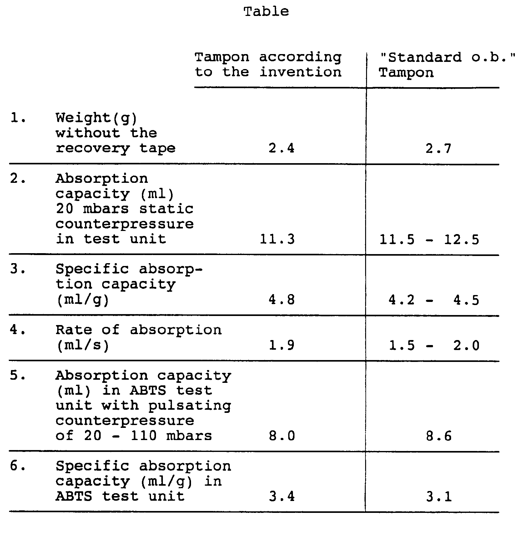
[0016] The absorption capacity values indicated in line 2 of the Table were determined in
a test unit, in which the tampon is surrounded by an elastic diaphragm which exerts
a static counterpressure on the tampon, whilst one end of the tampon is sprinkled
with water. This resulted in the specific fluid absorption capacity in ml/g of fibre
material of the tampon evident from line 3 of the Table.
[0017] The rate of absorption emerging from line 4 was determined in this test arrangement.
The values show that, at a weight of the tampon according to the invention reduced
by approximately 10%, the absorption capacity of the tampon is not essentially reduced
in relation to the known tampon, the rate of absorption is of the upper limit of that
of the known tampon, and the specific absorption capacity is appreciably higher than
in the known tampon. Since the specific absorption capacity is evidence of a better
utilization of the absorbency of the fibre material per unit weight, it is clear that
the tampon according to the invention can be produced more cheaply as a result of
the lower weight of material.
[0018] Lines 5 and 6 of the Table give values for the absorption capacity and the specific
absorption capacity determined in a test arrangement allowing test conditions such
as actually occur when the tampon is being worn.
[0019] The system designated as ABTS, corresponding to Absorptive Behaviour Test System,
is computer-assisted and serves for the acquisition and processing of measurement
data regarding the absorption behaviour of absorbent products and for controlling
the test cycle.
[0020] The test of the tampon is conducted under the following conditions which, as mentioned,
occur approximately in vivo:
- chemical/physical compositions of the test fluid
- spacial arrangement of the product, for example inclination
- positioning of the product in the measuring cell
- strength of the flow
- interruption (start/stop) of the flow
- pressure variant.
[0021] The test cycle is software-controlled automatically and allows a dialogue between
the operator and system. The measurement data are required automatically, their evaluation
taking place according to statistical factors. The test cycle for each random sample
can be tracked on a video screen by means of a measurement curve and, if appropriate,
printed out automatically. Furthermore, the fluid distribution in the product is represented
qualitatively and quantitatively. Moreover, the leakage behaviour of the tampon can
be checked. By leakage is meant the phenomenon in which menstruation fluid can escape
between the body wall and tampon. The feed of test fluid to the tampon is carried
out exclusively without pressure, since the fluid level is at the height of the test
tampon. The fluid is therefore sucked up into the tampon solely as a result of the
wetting of the tampon and the wick effect caused by the capillary forces of the latter,
and by means of the pulsating counterpressure on the tampon which is felt in practice.
[0022] The values determined with this ABTS test device illustrate, in lines 5 and 6 of
the Table, that, at the pulsating counterpressure indicated, the absorption capacity
of the tampon is only slightly lower than in the reference tampon, but here too the
specific absorption capacity of the tampon according to the invention per gram of
fibre material is approximately 10% higher than in the reference tampon.
[0023] The diameter of the tampon according to the invention is between 13 and 15 mm in
its final form. The central fibre core 16 has a diameter of approximately 4 to 8 mm.
[0024] Figure 4 shows an enlarged cross-sectional representation of the fibre structure
of the tampon according to the invention. It is possible to see clearly the central
fibre core 16, from which extend outwards eight longitudinal ribs 17 touching one
another at their outer ends 20. The tampon cross-section shows, moreover, that the
loose fibre structure with its coarser capillary structure of the longitudinal ribs
17 is preserved, despite the concentric pressure to which these longitudinal ribs
are exposed during the production of the final form of the tampon. In contrast, the
fibre core 16 having a high fibre compression guarantees a stability or buckling strength
which is twice as high as that of the reference tampon and which is of great importance
when the tampon is used as a digital tampon.
[0025] The figures illustrate an apparatus according to the invention for producing the
tampon. According to Figures 5 to 7, this apparatus consists of two groups of altogether
eight press dies arranged in a plane perpendicular to the press axis 21, the first
group of press dies forming press segments 22. In the closing position shown in Figure
6, the side flanks 23 of these four press segments 22 form respectively for each of
the four press dies of the second group guide surfaces which are designed as sliding
plates 24. At the same time, the press segments 22 and the sliding plates 24 serve,
as a preforming press, for pressing the winding blank 11 to produce the preform 15
in Figure 7. Exclusively press cutters 27 projecting from the end faces 25 and 26
of the press segments 22 and of the sliding plates 24 serve for pressing the blank.
It is evident from Figures 5 to 7 that the press cutters project from the end faces
25 and 26 of the press segments 22 and sliding plates 24 at equal angular distances
and over the same length. The shape and dimensions of all the press cutters are identical.
The press cutters are therefore also equipped at their front end with the same pressing
faces 28 which, in the exemplary embodiment illustrated, each extend parallel to the
press axis axis and are curved outwards in the manner of a semi-cylinder.
[0026] In the exemplary embodiment, the length and width of the press cutters 27 radial
relative to the press axis 21 amount to 10 mm and 2 mm respectively. In the closed
state of the preforming press, the pressing faces 26 of the press cutters 27 assume
a clear distance of 4 mm from the press axis 21 (Fig. 7). This distance can also be
smaller, for example 2 mm.
[0027] In contrastwith Figs. 6 and 7 a synchronous closing movement of the press segments
22 and sliding plates 24 related radially to the axis of the press and the winding
blank, respectively, Fig. 8 shows an interphase of this closing movement of all press
dies, whilst the final closing position of these press dies is shown in Fig. 9, which
position corresponds to the final dimension of the preform 15. The simultaneous pressing
movement of the press segments 22 and the sliding plates 24 has the advantage, that
the geometrical uniformity of the circumferential strip shaped portions 12 and 13
of the preform 15 will be enhanced. If the tampon is wetted by a fluid the tampon
will expand to a more circular shape than in case of the sequential movement of the
press dies as shown in Figs. 6 and 7.
[0028] If appropriate, however, the press faces can also have a mutually differing shape.
If appropriate, the sliding plates can also be designed differently, for example made
angular, arrow-shaped or drop-shaped. It is essential that they load and press only
a narrow circumferential portion of the blank corresponding approximately to a generatrix.
Furthermore, the cycle of movement of the two groups of press dies can, where appropriate,
also take place simultaneously or interruptedly in the preforming and post forming
and alternately between these two movement actions. Thus, it can be important, according
to the process of German Auslegeschrift 1,491,161, first to close all the press dies
simultaneously only up to the circumference of the blank 11, in order to centre the
blank as exact as possible in relation to the press axis 21, before commencing the
actual pressing operation, so as to ensure that the central fibre core 16 comes to
rest exactly in the middle of the tampon 10. This is desirable to obtain the highest
possible buckling strength or stability of the tampon, above all when the latter is
to be used as a digital tampon.
[0029] According to Fig. 10, the preforming press described is followed by a stationary
conical forming die 29. This forming die 29 is arranged coaxially relative to the
press axis 21. The entry orifice 30 of the forming die has a diameter which corresponds
approximately to the orifice of the preforming press in the closed state of its press
dies which is shown in Fig. 7. The inner face 31 is narrowed towards the cylindrical
exit orifice 32 according to an obtuse-angled circular cone, the cross-section of
the exit orifice 32 corresponding to the final cross-section of the finished tampon
10. Arranged on the input side of the preforming press is a ram 33 which serves for
introducing the winding blank 11 into the preforming press and for ejecting the preform
15 through the forming die 29. For this purpose, the ram 33 is arranged movably to
and fro coaxially in relation to the press axis 21. Rams of this type are known in
the art, and therefore there is no need to represent the driving elements for the
ram.
[0030] The production of the tampon according to the invention by means of the above-described
apparatus is carried out according to the following process: the essentially cylindrical
winding blank 11 is pressed solely on the narrow strip-shaped portions 12 and 13,
arranged at equal angular distances from one another, or the circumferential surface
of the winding blank, to produce the preform 15 which, as seen in cross-section, consists
of the central approximately circular fibre core 16 of high compression and buckling
strength or stability and of longitudinal ribs 17 of softer fibre structure extending
radially outwards from the fibre core 16. At the same time, the longitudinal ribs
17 are separated from one another by the outwardly open longitudinal grooves 18. Thereafter,
only the soft longitudinal ribs 17 of the preform 15 are exposed to a low uniform
pressure radial relative to the longitudinal mid-axis of the preform, until the outer
ends of the longitudinal ribs have produced a soft essentially smoothly cylindrical
surface of smaller diameter corresponding to the final form of the tampon 10. As mentioned,
preferably before the actual pressing, the winding blank 11 is centred relative to
the press axis 21 of the preforming press as a result of the simultaneous concentric
closing of the press segments 22 and sliding plate 24 approximately as far as the
circumference of the winding blank.
[0031] After the pressing of the preform, the latter is ejected through the forming die
29 by means of the ram 33 and thereby brought to the final dimension of the tampon
which is determined by the exit orifice 32 of the forming die 29.
1. Tampon, especially for feminine hygiene, formed from an approximately cylindrical
blank which is shaped by winding up a portion of length of tape-shaped nonwoven material,
and the circumferential surface of which is pressed radially relative to the longitudinal
mid-axis of the blank over an even number of at least 6 portions mutually adjacent
in the circumferential direction of the winding blank, characterized in that only
narrow strip-shaped portions of the circumferential surface of the winding blank,
which are arranged at equal angular distances from one another, are pressed to produce
a preform which, as seen in cross-section, consists of a central approximately circular
fibre core (16) of high compression and buckling strength and of longitudinal ribs
(17) of softer fibre structure and with a coarser capillary structure which extend
radially outwards from the fibre core and which are separated from one another by
outwardly open longitudinal grooves (18), and in that, accordingly, only the soft
longitudinal ribs of the preform (15) have been exposed to a low uniform pressure,
radial relative to the longitudinal mid-axis of the preform, in such a way that the
outer ends of the longitudinal ribs form a soft essentially smoothly cylindrical surface
of smaller diameter, with the coarser capillary structure corresponding to the final
form of the tampon being maintained (10).
2. Tampon according to Claim 1, the blank of which is produced from a needled nonwoven
tape consisting of 100 % rayon fibre, characterized in that the tampon, with a weight
of 2.4 g without the recovery tape, has a specific absorption capacity of 4.8 mi/g
at an absorption rate of 1.9 mi/s.
3. Tampon according to Claim 2, characterized in that the absorption capacity of the
tampon amounts to 11.3 ml at a static counterpressure of 20 mbars.
4. Tampon according to Claims 1 and 3, characterized in that, at a pulsating counterpressure
of 20 to 110 mbars, the absorption capacity of the tampon amounts to 8.0 ml and the
specific absorption capacity to 3.4 ml/g.
5. Tampon according to one of Claims 1 to 4, characterized in that the diameter of
the tampon, in its final form, amounts to between 13 and 15 mm, the central fibre
core having a diameter of 4 to 8 mm.
6. Process for producing the tampon according to Claims 1 to 5, in which an essentially
cylindrical blank is shaped by winding up a portion of length of tape-shaped nonwoven
material, the circumferential surface of which is pressed radially relative to the
longitudinal mid-axis of the blank over an even number of at least six portions mutually
adjacent in the circumferential direction of the winding blank, characterized in that
only narrow strip-shaped portions of the circumferential surface of the winding blank,
which are arranged at equal angular distances from one another, are pressed to produce
a preform which, as seen in cross-section, consists of a central approximately circular
fibre core of high compression and buckling strength and of longitudinal ribs of a
softer fibre structure with a coarser capillary structure which extend radially outwards
from the fibre core and which are separated from one another by outwardly open longitudinal
grooves, and in that, accordingly, only the soft longitudinal ribs of the preform
are exposed to a low uniform pressure, radial relative to the longitudinal mid-axis
of the preform, until the outer ends of the longitudinal ribs have formed a soft essentially
smoothly cylindrical surface of smaller diameter, with the coarser capillary structure
corresponding to the final form of the tampon being maintained.
7. Process according to Claim 6, characterized in that the winding blank is centred
before the pressing.
8. Process according to Claim 6, characterized in that the preform is moved for shaping
purposes.
9. Apparatus for producing the tampon according to one of Claims 1 to 8 and for carrying
out the process according to one of Claims 6 to 8, consisting of two groups of altogether
at least six press dies arranged in a plane perpendicular to the press axis, the first
group of press dies forming press segments, of which the side flanks, in the closing
position of the press segments, form respectively for each of the press dies of the
second group guide surfaces which are designed as sliding plates, in the closed state
the end faces of the press dies forming an essentially cylindrical pressing face,
characterized in that the press segments (22) and the sliding plates (24) form a preforming
press for the pressing of a preform (15), press cutters (27) projecting from the end
faces (25, 26) of the press segments (22) and of the sliding plates (24), and in that
the preforming press is followed by a stationary conical forming die (29) which is
arranged coaxially relative to the press axis, and the entry orifice (30) of which
is calculated to match the diameter of the orifice of the preforming press, when its
press dies (22, 24) are in the closed state, and the exit orifice (32) of which is
calculated to match the final cross-section of the finished tampon (10).
10. Apparatus according to Claim 9, characterized in that the press cutters (27) project
from the end faces (25, 26) of the press segments (22) and sliding plates (24) at
equal angular distances (a) and over the same length.
11. Apparatus according to Claims 9 or 10, characterized in that all the press cutters
(27) have the same pressing faces (28).
12. Apparatus according to Claim 11, characterized in that the pressing face (28)
of the press cutters (27) which is parallel to the press axis (21) is curved outwards.
13. Apparatus according to Claims 9 or 10, characterized in that the press cutters
(27) have pressing faces (28) of differing form.
14. Apparatus according to one of Claims 9 to 13, characterized in that the length
and width of the press cutters (27), radial relative to the press axis (21), amounts
to 10 and 2 mm respectively.
15. Apparatus according to one of Claims 9 to 14, characterized in that, when the
press is in the closed state, the pressing faces (28) of the press cutters (26) assume
a clear distance of 2 to 4 mm from the press axis (21).
16. Apparatus according to Claim 9, characterized in that the conical forming die
(29) has an entry orifice (30) with a diameter of 20 mm and an exit orifice (32) with
a diameter of 13 mm.
17. Apparatus according to one of Claims 9 to 16, characterized in that all the press
dies (22, 24) are first closable concentrically relative to the press axis (21) to
approximately the diameter of the winding blank (11), subsequently the press segments
(22) of the first group are simultaneously movable concentrically into the closing
position, and thereafter the sliding plates (24) of the second group are movable to
the final dimension of the preform (15).
18. Apparatus according to one of Claims 9 to 16, characterized in that the press
segments (22) and the sliding plates (24) are simultaneously movable concentrically
relative to the press axis (21) into the closing position which corresponds to the
final dimension of the preform (15).
19. Apparatus according to one of Claims 9 to 18, characterized in that, arranged
on the input side of the preforming press, there is a ram (33) which is movable axially
to and fro for ejecting the preform (15) from the preforming press and for pushing
the preform through the conical forming die (29).
1. Tampon, insbesondere für die Frauenhygiene, der aus einem durch Aufwickeln eines
Längenabschnitts aus bandförmigem Faservlies geformten, etwa zylindrischen Rohling
gebildet ist, dessen Umfangsfläche auf einer geraden Anzahl von mindestens sechs in
Umfangsrichtung des Wickelrohlings benachbarten Abschnitten radial zur Mittellängsachse
des Rohlings gepreßt ist, dadurch gekennzeichnet, daß ausschließlich schmale, streifenförmige,
in gleichen Winkelabständen voneinander angeordnete Abschnitte der Umfangsfläche des
Wickelrohlings zu einem Vorformling gepreßt sind, der, im Querschnitt gesehen, aus
einem zentralen, etwa kreisförmigen Faserkern (16) hoher Verdichtung und Knickfestigkeit
und sich von dem Faserkern radial nach außen erstreckenden Längsrippen (17) von weicherer
Faserstruktur mit gröberer Kapillarstruktur besteht, die durch nach außen offene Längsnuten
(18) voneinander getrennt sind, und daß danach ausschließlich die weichen Längsrippen
des Vorformlings (15) einen schwachen, gleichmässigen, zur Mittellängsachse des Vorformlings
radialen Druck ausgesetzt wurden, derart, daß die äußeren Enden der Längsrippen eine
weiche, im wesentlichen glattzylindrische Oberfläche kleineren Durchmessers unter
Beibehaltung der gröberen Kappilarstruktur entsprechend der Endform des Tampons bilden
(10).
2. Tampon nach Anspruch 1, dessen Rohling aus einem genadelten Vliesband aus 100%
Rayonfaser gebildet ist, dadurch gekennzeichnet, daß der Tampon mit einem Gewicht
von 2,4 g ohne Rückholband eine spezifische Absorptionsfähigkeit von 4,8 ml/g bei
einer Absorptionsgeschwindigkeit von 1,9 ml/s aufweist.
3. Tampon nach Anspruch 2, dadurch gekennzeichnet, daß die Absorptionsfähigkeit des
Tampons bei einem statischen Gegendruck von 20 mbar 11,3 ml beträgt.
4. Tampon nach den Ansprüchen 1 bis 3, dadurch gekennzeichnet, daß die Absorptionsfähigkeit
des Tampons bei einem pulsierenden Gegendruck von 20 bis 110 mbar 8,0 ml und die spezifische
Absorptionsfähigkeit 3,4 ml/g betragen.
5. Tampon nach einem der Ansprüche 1 bis 4, dadurch gekennzeichnet, daß der Durchmesser
des Tampons in seiner Endform zwischen 13 und 15 mm beträgt, wobei der zentrale Faserkern
einen Durchmesser von 4 bis 8 mm aufweist.
6. Verfahren zum Herstellen des Tampons nach den Ansprüchen 1 bis 5, bei dem ein im
wesentlichen zylindrischer Rohling durch Aufwickeln eines Längenabschnitts aus bandförmigem
Faservlies geformt wird, dessen Umfangsfläche auf einer geraden Anzahl von mindestens
sechs in Umfangsrichtung des Wickelrohlings benachbarten Abschnitten radial zur Mittellängsachse
des Rohlings gepreßt wird, dadurch gekennzeichnet, daß ausschließlich schmale, streifenförmige,
in gleichen Winkelabständen voneinander angeordnete Abschnitte der Umfangsfläche des
Wickelrohlings zu einem Vorformling gepreßt werden, der, im Querschnitt gesehen, aus
einem zentralen, etwa kreisförmigen Faserkern hoher Verdichtung und Knickfestigkeit
und sich von dem Faserkern radial nach außen erstreckenden Längsrippen von weicherer
Faserstruktur mit gröberer Kapillarstruktur besteht, die durch nach außen offene Längsnuten
voneinander getrennt sind, und daß danach ausschließlich die weichen Längsrippen des
Vorformlings einem schwachen, gleichmässigen, zur Mittellängsachse des Vorformlings
radialen Druck so lange ausgesetzt werden, bis die äußeren Enden der Längsrippen eine
weiche, im wesentlichen glattzylindrische Oberfläche kleineren Durchmessers unter
Beibehaltung der gröberen Kapillarstruktur entsprechend der Endform des Tampons gebildet
haben.
7. Verfahren nach Anspruch 6, dadurch gekennzeichnet, daß der Wickelrohling vor dem
Pressen zentriert wird.
8. Verfahren nach Anspruch 6, dadurch gekennzeichnet, daß der Vorformling zur Formgebung
bewegt wird.
9. Vorrichtung zur Herstellung des Tampons nach einem der Ansprüche 1 bis 5 sowie
zur Durchführung des Verfahrens nach einem der Ansprüche 6 bis 8, bestehend aus zwei
Gruppen von insgesamt mindestens sechs in einer zur Pressenachse senkrechten Ebene
angeordneten Preßwerkzeugen, wobei die erste Gruppe der Preßwerkzeuge Preßsegmente
bildet, deren Seitenflanken in der Schließstellung der Preßsegmente für je eines der
Preßwerkzeuge der zweiten Gruppe Führungsflächen bilden, die als Schiebeplatten ausgebildet
sind, wobei die Stirnflächen der Preßwerkzeuge beider Gruppen im geschlossenen Zustand
eine im wesentlichen zylindrische Preßfläche bilden, dadurch gekennzeichnet, daß die
Preßsegmente (22) und die Schiebeplatten (24) eine Vorformpresse zum Pressen eines
Vorformlings (15) bilden, wobei von den Stirnflächen (25, 26) der Preßsegmente (22)
und der Schiebeplatten (24) Preßschneiden (27) vorstehen, und daß der Vorformpresse
ein feststehendes, konisches Formwerkzeug (29) nachgeschaltet ist, daß koaxial zur
Pressenachse angeordnet ist und dessen Eintrittsöffnung (30) dem Durchmesser der Öffnung
der Vorformpresse im geschlossenen Zustand ihrer Preßwerkzeuge (22, 24) und deren
Austrittsöffnung (32) dem Endquerschnitt des fertigen Tampons (10) entsprechend bemessen
ist.
10. Vorrichtung nach Anspruch 9, dadurch gekennzeichnet, daß die Preßschneiden (27)
von den Stirnflächen (25, 26) der Preßsegmente (22) und Schiebeplatten (24) in gleichen
Winkelabständen ( ) auf gleicher Länge vorstehen.
11. Vorrichtung nach den Ansprüchen 9 oder 10, dadurch gekennzeichnet, daß alle Preßschneiden
(27) die gleichen Preßflächen (28) aufweisen.
12. Vorrichtung nach Anspruch 11, dadurch gekennzeichnet, daß die zur Pressenachse
(21) parallele Preßfläche (28) der Preßschneiden (27) nach außen gewölbt ist.
13. Vorrichtung nach den Ansprüchen 9 oder 10, dadurch gekennzeichnet, daß die Preßschneiden
(27) Preßflächen (28) unterschiedlicher Form aufweisen.
14. Vorrichtung nach einem der Ansprüche 9 bis 13, dadurch gekennzeichnet, daß die
zur Pressenachse (21) radiale Länge bzw. Breite der Preßschneiden (27) 10 bzw. 2 mm
beträgt.
15. Vorrichtung nach einem derAnsprüche 9 bis 14, dadurch gekennzeichnet, daß im geschlossenen
Zustand der Presse die Preßflächen (28) der Preßschneiden (26) einen lichten Abstand
von 2 bis 4 mm von der Pressenachse (21) einnehmen.
16. Vorrichtung nach Anspruch 9, dadurch gekennzeichnet, daß das konische Formwerkzeug
(29) eine Eintrittsöffnung (30) mit einem Durchmesser von 20 mm und eine Austrittsöffnung
(32) von 13 mm aufweist.
17. Vorrichtung nach einem derAnsprüche 9 bis 16, dadurch gekennzeichnet, daß sämtliche
Preßwerkzeuge (22, 24) zunächst bis auf etwa den Durchmesser des Wickelrohlings (11)
konzentrisch zur Pressenachse (21) schließbarsind und anschließend die Preßsegmente
(22) derersten Gruppe gleichzeitig konzentrisch in die Schließstellung bewegbar sind
und daraufhin die Schiebeplatten (24) der zweiten Gruppe bis auf das Endmaß des Vorformlings
(15) bewegbar sind.
18. Vorrichtung nach einem der Ansprüche 9 bis 16, dadurch gekennzeichnet, daß die
Preßwerkzeuge (22) und die Schiebeplatten (24) gleichzeitig konzentrisch relativ zu
der Pressenachse (21) in die Schließstellung, die dem endgültigen Durchmesser des
Vorformlings (15) entspricht, bewegbar sind.
19. Vorrichtung nach einem der Ansprüche 9 bis 18, dadurch gekennzeichnet, daß an
der Eingangsseite der Vorformpresse ein Stössel (33) angeordnet ist, der zum Ausstoßen
des Vorformlings (15) aus der Vorformpresse und zum Hindurchstoßen des Vorformlings
durch das konische Formwerkzeug (29) axial hin und her bewegbar ist.
1. Tampon particulièrement pour l'hygiène féminine, formé à partir d'une pièce approximativement
cylindrique qui est formée par enroulement d'une portion de longueur de matériau non
tissé en bande, et dont la surface circonférentielle est comprimée radialement par
rapport à l'axe médian longitudinal de la pièce, sur un nombre pair d'au moins 6 portions
mutuellement adjacentes dans la direction circonférentielle de la pièce d'enroulement,
caractérisé en ce que seules des portions étroites en bandes de la surface circonférentielle
de la pièce d'enroulement, qui sont disposées à égales distances angulaires les unes
par rapport aux autres, sont comprimées pour obtenir une pré-forme qui, telle qu'on
peut l'observer en coupe transversale, se compose d'un noyau de fibres central approximativement
circulaire (16) de forte résistance à la compression et à la déformation, et de nervures
longitudinales (17) de structure de fibre plus douce et avec une structure capillaire
plus grossière qui s'étendent radialement à l'extérieur du noyau de fibres et qui
sont séparées les unes des autres par des encoches longitudinales ouvertes vers l'extérieur
(13), et en ce que, en conséquence, seules les nervures longitudinales douces de la
pré-forme (15) ont été soumises à une faible compression uniforme, radialement par
rapport à l'axe médian longitudinal, de telle sorte que les extrémités extérieures
des nervures longitudinales forment une surface cylindrique douce essentiellement
lisse d'un diamètre plus petit, la structure capillairc plus grossière correspondant
à la forme finale du tampon maintenu (10).
2. Un tampon selon la Revendication 1, dont la pièce est produite à partir d'une bande
non tissée aiguillée composée de 100 % de fibre de cellulose, caractérisé en ce que
le tampon, qui pèse 2,4 g sans la bande de recouvrement, présente un pouvoir d'absorption
spécifique de 4,8 ml/g à une vitesse d'absorption de 1,9 ml/s.
3. Un tampon selon la Revendication 2, caractérisé en ce que le pouvoir d'absorption
du tampon est de 11,3 ml à une contrepression statistique de 20 mbars.
4. Un tampon selon les Revendications 1 à 3, caractérisé en ce qu'à une contrepression
pulsatoire de 20 à 110 mbars, le pouvoir d'absorption du tampon est de 8,0 ml et le
pouvoir d'absorption spécifique de 3,4 ml/g.
5. Un tampon selon une des Revendications 1 à 4, caractérisé en ce que le diamètre
du tampon, dans sa forme finale, se situe entre 13 et 15 mm, le noyau de fibre central
présentant un diamètre de 4 à 8 mm.
6. Un procédé pour la production du tampon selon les Revendications 1 à 5, selon lequel
une pièce essentiellement cylindrique est formée par enroulement d'une portion de
longueur de matériau non tissé en bande, dont la surface circonférentielle est comprimée
radialement par rapport à l'axe médian longitudinal de la pièce, sur un nombre pair
d'au moins 6 portions mutuellement adjacentes dans la direction circonférentielle
de la pièce d'enroulement, caractérisé en ce que seules des portions étroites en bandes
de la surface circonférentielle de la pièce d'enroulement, qui sont disposées à égales
distances angulaires les unes par rapport aux autres, sont comprimées pour obtenir
une pré-forme qui, telle qu'on peut l'observer en coupe transversale, se compose d'un
noyau de fibres central approximativement circulaire de forte résistancc à la compression
et à la déformation, et de nervures longitudinales de structure de fibre plus douce
et avec une structure capillaire plus grossière qui s'étendent radialement à l'extérieur
du noyau de fibres et qui sont séparées les unes des autres par des encoches longitudinales
ouvertes vers l'extérieur, et en ce que, en conséquence, seules les nervures longitudinales
douces de la pré-forme sont soumises à une faible compression uniforme, radialement
par rapport à l'axe médian longitudinal, jusqu'à ce que les extrémités extérieures
des nervures longitudinales aient formé une surface cylindrique douce essentiellement
lisse d'un diamètre plus petit, la structure capillaire plus grossière correspondant
à la forme finale du tampon maintenu.
7. Un procédé selon la Revendication 6, caractérisé en ce que la pièce d'enroulement
est centrée avant compression.
8. Un procédé selon la Revendication 6, caractérisé en ce que la pré-forme est déplacée
pour des raisons de formage.
9. Un dispositif pour la production du tampon selon une des Revendications 1 à 8 et
pour réaliser le procédé selon une des Revendications 6 à 8, composé de 2 groupes
chacun d'au moins 6 moules de presse disposés sur un plan perpendiculaire à l'axe
de la presse, le premier groupe de moules de presse formant des segments de presse,
dont les flancs, en position fermée des segments de presse forment respectivement
pour chacun des moules de presse des surfaces de guidage du second groupe qui sont
conçues comme plaques coulissantes, les faces d'extrémité des moules de presse formant
une face de compression essentiellement cylindrique, caractérisé en ce que les segments
de presse (22) et les plaques coulissantes (24) forment une presse préformante pour
la compression de la pré-forme (15), des couteaux de la presse (27) dépassant à partir
des faces d'extrémité (25,26) des segments de presse (22) et des plaques coulissantes
(24), et en ce que la presse préformante est suivie d'un moule formant conique fixe
(29) qui est disposé coaxialement par rapport à l'axe de la presse, et dont l'orifice
d'entrée (30) est calculé pour correspondre au diamètre de l'orifice de la presse
préformante, lorsque ses moules de presse (22,24) sont en position fermée, et dont
l'orifice de sortie (32) est calculé pour correspondre à la section transversale finale
du tampon fini (10).
10. Un dispositif selon la Revendication 9, caractérisé en ce que les couteaux de
la presse (27) dépassent des faces d'extrémité (25, 26) des segments de la presse
(22) et des plaques coulissantes (24) à des distances angulaires égales (a) et sur
la mêmc longueur.
11. Un dispositif selon la Revendication 9 ou 10, caractérisé en ce que tous les couteaux
de la presse (27) ont les mêmes faces de compression (28).
12. Un dispositif selon la Revendication 11, caractérisé en ce que la face de compression
(28) des couteaux de la presse (27) qui est parallèle à l'axe de la presse (21) est
cintrée vers l'extérieur.
13. Un dispositif selon la Revendication 9 ou 10, caractérisé en ce que les couteaux
de la presse (27) présentent des faces de compression (28) de différentes formes.
14. Un dispositif selon une des Revendications 9 à 13, caractérisé en ce que la longueur
et la largeur des couteaux de la presse (27), disposés radialement par rapport à l'axe
de la presse (21), s'élèvent respectivement à 10 et 2 mm.
15. Un dispositif selon une des Revendications 9 à 14, caractérisé en ce que, lorsque
la presse se trouve en position fermée, les faces de compression (28) des couteaux
de la presse (26) se tenant à une distance définie de 2 ou 4 mm de l'axe de la presse
(21).
16. Un dispositif selon la Revendication 9, caractérisé en ce que le moule formant
conique (29) possède un orifice d'entrée (30) ayant un diamètre de 20 mm et un orifice
de sortie (32) ayant un diamètre de 13 mm.
17. Un dispositif selon une des Revendications 9 à 16, caractérisé en ce que tous
les moules de presse (22, 24) peuvent d'abord être fermés de façon concentrique par
rapport à l'axe de la presse (21) au diamètre approximatif de la pièce d'enroulement
(11), ensuite les segments de la presse (22) du premier groupe peuvent se déplacer
simultanément de façon concentrique pour atteindre la position fermée, suite à quoi
les plaques coulissantes (24) du second groupe peuvent se déplacer pour atteindre
la dimension finale de la pré-forme (15).
18. Un dispositif selon une des Revendications 9 à 16, caractérisé en ce que les segments
de presse (22) et les plaques coulissantes (24) peuvent se déplacer simultanément
de façon concentrique par rapport à l'axe de la presse (21) dans la position fermée
qui correspond à la dimension finale de la pré-forme (15).
19. Un dispositif selon une des Revendications 9 à 16, caractérisé en ce que il se
trouve un vérin, disposé sur la face d'entrée de la presse préformante, qui se déplace
axialement selon un mouvement de va et vient, éjectant la pré-forme (15) de la presse
préformantc et pour pousser la pré-forme à travers le moule formant conique (29).