|
(11) | EP 0 235 631 B1 |

| (12) | EUROPEAN PATENT SPECIFICATION |
|
|
| (54) |
Method of forming halftone screen Verfahren zur Erzeugung eines Halbtonrasters Procédé pour faire un écran de demi-teintes |
|
|
|||||||||||||||||||||||||||||||
| Note: Within nine months from the publication of the mention of the grant of the European patent, any person may give notice to the European Patent Office of opposition to the European patent granted. Notice of opposition shall be filed in a written reasoned statement. It shall not be deemed to have been filed until the opposition fee has been paid. (Art. 99(1) European Patent Convention). |
[0001] The present invention relates to a method of producing a halftone dot image according to the pre-characterizing part of claim 1.
[0002] Recently, image scanning reading and recording apparatus are widely used in the field of printing and graphic art for electrically processing image information of originals to produce original film plates with a view to simplifying the entire process and improving the quality of printed images.
[0003] The image scanning reading and recording apparatus are basically constructed of an input unit, a control unit, and an output unit. In the input unit, an original delivered to an image reader is scanned by a laser beam or the like, and image information of the original is converted to an electric signal representative of different intensities of reflected laser light. The photoelectrically converted image information is then processed in the control unit for tone correction, outline emphasis, or the like according to platemaking conditions. The image information which is processed by the control unit is thereafter fed to the output unit in which it is converted again to a light signal such as a laser beam. The light signal is applied to a recording medium such as a photo-sensitive material to record the image thereon. The image on the recording medium is then developed by a developing device, after which the recording medium is used as an original film plate.
[0004] Where an original to be printed or reproduced bears a continuous-tone image such as a photograph or a painting, it is necessary to break up the original image into halftone dots in order to reproduce tone gradations clearly. More specifically, a continuous-tone image is converted to a halftone dot image which is composed of closely spaced dots of different sizes according to gradations of density of the image. One method of breaking up a continuous-tone image into halftone dots is to apply a light signal commensurate with the continuous-tone image to a film through a contact screen having a vignetted dot pattern. The aforesaid image scanning reading and recording apparatus employ a process for electrically forming a halftone screen corresponding to such a contact screen.
[0005] One preferred example of a conventional method of forming a halftone screen will briefly be described below based on the invention disclosed in Japanese Patent Publication No. 52-49361 claiming Convention Priority based on West German Patent Application No. 1901101.9. (corresponding to US-A-3 657 472).
[0006] FIG. 1 of the accompanying drawings shows a basic periodic portion 2 of a halftone screen which is electrically formed. The halftone screen is composed of repetitions of one pattern, and the minimum unit of the halftone screen is the basic periodic portion 2. The basic periodic portion 2 is constructed of eight scanning lines S1 through S8 arranged side by side in the direction Y. Each of the scanning lines S1 through S8 forms an element of the basic periodic portion 2 with an inherent voltage signal that varies in the recording direction X. The voltages of the scanning lines S1, S2, S4, S5 passing through points A through D in a dot 4 are high, and the scanning line S3 passing through a point E is low. The voltages of the sanning lines S1 through S5 are selected to become gradually lower from the points A through D to the point E. The voltage signals or halftone screen signals of the scanning lines S1 through S8 may be produced by superposing a plurality of alternating voltage signals of triangular waveform which have different periods, and slightly shifting the phases of those voltage signals.
[0007] When converting a multicolor image or the like to dots, it is necessary to generate a plurality of halftone screens and superpose halftone dot images produced respectively by those halftone screens. In order to prevent a moire pattern from being produced when the halftone screens are superposed, the halftone screens are formed while they are rotated a prescribed angle ϑ with respect to the recording direction X.
[0008] The basic periodic portion 2 is periodically produced frequently enough to cover a scanned region of the original, for thereby producing a halftone screen. The halftone screen signals constituting the halftone screen are superposed on an image signal that has optically been read from the original by the input unit of the image scanning reading and recording apparatus, so that a halftone-dot image is formed on a film plate.
[0009] The halftone screen signals can sufficiently accurately represent the gradations of the halftone screen in the case where the width of each of the scanning lines S1 through S8 of the basic periodic portion 2 is sufficiently smaller than the width of the basic periodic portion 2 in the direction Y and hence the voltages of the halftone screen signals continuously vary in the direction Y. However, if the width of each of the scanning lines S1 through S8 is not negligible with respect to the width of the basic periodic portion 2 in the direction Y, the voltages of the halftone screen signals vary in a step-like discrete manner between the adjacent scnanning lines S1 through S8. In such a case, the voltages at the points A through D, which are to be of maximum values, may gradually vary in the scanning lines S1, S2, S4, S5, and such a voltage variation may cause a periodic pattern to be produced in the basic periodic portion 2. Should such a periodic pattern be large enough to be visually conspicuous, an unsightly pattern, other than the gradations of the original, would be introduced into the halftone dot image as with a moire pattern.
[0010] In accordance with the pre-characterizing part of claim 1 (and claim 2), GB-A-20 98 022 discloses a method for producing a halftone dot image by digitally generating halftone dots. Specificly, the reference discloses to reduce the halftone dot data to be stored in a memory. The document does not disclose to eliminate a periodic pattern from the halftone image when the halftone screen and image signals are superposed.
[0011] It is the object of the present invention to provide a method of the above identified type in which a periodic pattern in the halftone dot image is eliminated.
[0012] This object is achieved according to the features of the characterizing part of claim 1 and claim 2.
[0013] The present invention provides for an analog method for generating a halftone dot image using a halftone screen which is specificly intended to eliminate a periodic pattern from being produced in the basic periodic portion, and to eliminate periodic patterns in the halftone dot image when the screen signal and the image signal are superposed to produce the halftone image.
[0014] According to the present invention the number of scanning lines is selected so as to pass through areas of the dots where the halftone screen signals are of a maximum level.
[0015] The above and other objects, features and advantages of the present invention will become more apparent from the following description when taken in conjunction with the accompanying drawings in which preferred embodiments of the present invention are shown by way of illustrative example.
BRIEF DESCRIPTION OF THE DRAWINGS
[0016]
FIG. 1 is a view of a basic periodic portion of a halftone screen formed by a conventional method;
FIG. 2 is a view explanating a method of forming a halftone screen according to the present invention;
FIG. 3 is a view of a basic periodic portion of a halftone screen formed by the method of the present invention; and
FIG. 4 is a view explanating a method of forming a halftone screen according to another embodiment of the present invention.
DETAILED DESCRIPTION OF THE PREFERRED EMBODIMENTS
[0017] FIG. 2 fragmentarily shows a basic periodic portion 10 of a halftone screen which is formed by electrically generating a halftone screen signal. The halftone screen is inclined at a screen angle ϑ in order to minimize a moire pattern that would be produced in a halftone dot image.
[0018] So as to allow the basic periodic portion 10 to be a minimum basic unit of a halftone screen constituting a halftone dot image, the screen angle ϑ is required to be selected as follows:
where m and n are integers. Moreover, since the basic periodic portion 10 must be composed of an integral number of scanning lines arranged side by side in the direction Y, the following relationship should be met:
where ma is the length of the basic periodic portion 10 in the direction Y with a being the pitch of a dot 12 surrounded by points A through D, P is the width of each of the scanning lines, and α is the number of the scanning lines which constitute the basic periodic portion 10.
[0019] In order that all of the adjacent dots 12 are composed of an integral number of scanning lines in the basic periodic portion 10, an integral number of scanning lines need to be disposed between the points A, D, for example. More specifically, the distance ℓ1 between the points A, D in the direction Y must be given by:
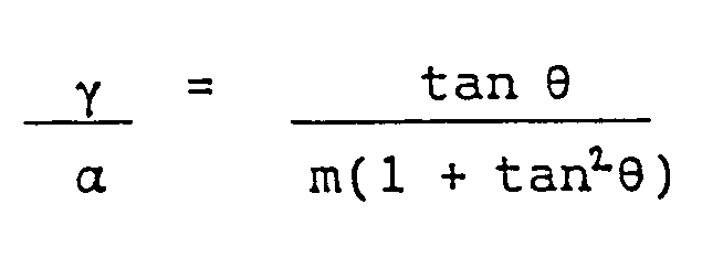
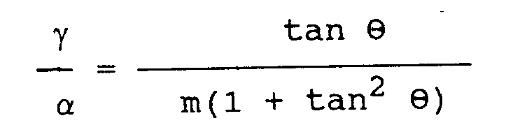
where γ is the number of scanning lines arranged between the points A, D. The distance ℓ1 can be expressed by:
Therefore, the following equation can be derived from the equations (2), (3), and (4):
When the relationship (5) is established, scanning lines always pass through the points A, D where the voltage is maximum in the dot 12, and image information corresponding to these points is reproduced by halftone screen signals of the same level.
[0020] Likewise, image information corresponding to the points B, C is reproduced by halftone screen signals of the same level. As a result, by selecting the number of scanning lines of the halftone screen so that the equation (5) will be established, the voltages of the halftone screen signals at the points A through D are rendered constant, and hence there is no danger of a periodic pattern produced in a halftone dot image constituted by a repeated pattern of the basic periodic portion 10 shown in FIG. 2.
[0021] Where tan ϑ is selected to be 1/2, i.e., the screen angle ϑ of the halftone screen is selected to be about 27°, for example, the number of scanning lines need to be selected such that α is a multiple of 5 from the equation (5). In this case, therefore, no periodic pattern appears in the halftone dot image by forming the basic periodic portion 10 of ten scanning lines S1 through S10 as shown in FIG. 3.
[0022] In order to eliminate a periodic pattern in the basic periodic portion 10 only in the direction Y, conditions need to be established such that an integral number of scanning lines will be provided between the points A, C in a dot 12 as illustrated in FIG. 4. More specifically, the distance ℓ2 in the direction Y between the points A, C of the dot 12 is required to be expressed by:
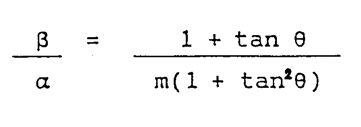
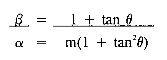
where β is the number of scanning lines between the points A, C, and P is the width of each of the scanning lines, as described above. Assuming that the screen angle of the halftone screen is expressed by ϑ, the distance ℓ2 can be given by:
Consequently, where the following equation can be derived from the equations (2), (6), and (7):
image information corresponding to the points A, C in the dot 12 is reproduced by halftone screen signals of the same level at all times. The generation of a periodic pattern in these points is therefore prevented.
[0023] Where tanϑ is selected to be 1/5, i.e., the screen angle ϑ of the halftone screen is selected to be about 11°, for example, and when α is set to a multiple of 13 from the equation (8), e.g., when a basic periodic portion 10 is constructed of 39 scanning lines, no periodic pattern is produced in the halftone dot image. In order to eliminate a periodic pattern also in the direction X, α is required to be set to a multiple of 26 from the equation (5). In such a case, the number of scanning lines is a multiple of 26.
[0024] With the present invention, as described above, when forming a halftone dot image by superposing an image signal produced by optically scanning an original on an electrically generated halftone screen signal, each dot constituted by the halftone dot screen is constructed of an integral number of scanning lines commensurate with the size and angle of the halftone screen. Therefore, there is produced no portion with periodically varying dot size in a halftone dot image formed by the above halftone screen signal. As a consequence, there is no danger of a periodic pattern produced in the halftone dot image. According to the present invention, therefore, it is possible to form a clearer film plate.
1. A method of producing a halftone dot image using a halftone screen by superposing
image information produced by scanning an original on the halftone screen, the halftone
screen being composed of a plurality of scanning lines (S₁ - S₈) constituted by electrically
generated halftone screen signals and arranged side by side in a direction normal
to a scanning direction in which the scanning lines extend, said method comprising
the steps of:
forming each dot (12) of said halftone screen with an integral number of scanning lines commensurate with a screen angle (ϑ) of the halftone screen; and
equalizing the halftone screen signals in level at mutually corresponding corner areas (A,B,C,D) in the respective dots of said halftone screen;
characterized in that the halftone screen is composed of a repeated pattern of minimum basic periodic portions (2), the number α of scanning lines which constitute each of said basic periodic portions being selected according to the following equation:
where ϑ is the screen angle, γ is the number of scanning lines disposed between closest vertices of a square dot with respect to said direction normal to the scanning direction, and m is an integer, thereby preventing a periodic pattern from being generated in said halftone dot image.
2. A method of producing a halftone dot image using a halftone screen by superposing
image information produced by scanning an original on the halftone screen, the halftone
screen being composed of a plurality of scanning lines (S₁ - S₈) constituted by electrically
generated halftone screen signals and arranged side by side in a direction normal
to a scanning direction in which the scanning lines extend, said method comprising
the steps of:
forming each dot (12) of said halftone screen with an integral number of scanning lines commensurate with a screen angle (ϑ) of the halftone screen; and
equalizing the halftone screen signals in level at mutually corresponding corner areas (A,B,C,D) in the respective dots of said halftone screen;
characterized in that the halftone screen is composed of a repeated pattern of minimum basic periodic portions (2), the number α of scanning lines which constitute each of said basic periodic portions being selected according to the following equation:
where ϑ is the screen angle, β is the number of scanning lines disposed between farthest vertices (A, C) of a square dot (12) with respect to the direction normal to the scanning line direction, and m is an integer, thereby preventing a periodic pattern from being generated in said halftone dot image.
3. A method according to claim 1 or 2, wherein the number of scanning lines is selected
so as to pass through areas of the dots wherein the halftone screen signals are of
a maximum level.
1. Verfahren zum Erzeugen eines Halbtonpunktbildes unter Verwendung eines Halbtonrasters,
indem durch Abtasten einer Vorlage erzeugte Bildinformation dem Halbtonraster überlagert
wird, wobei das Halbtonraster sich aus mehreren Abtastzeilen (S₁ - S₈) zusammensetzt,
die gebildet werden durch elektrisch erzeugte Halbtonrastersignale, und die in einer
Richtung senkrecht zur Abtastrichtung, in der sich die Abtastzeilen erstrecken, Seite
an Seite angeordnet sind, wobei das Verfahren folgende Schritte umfaßt:
jeder Fleck (12) des Halbtonrasters wird mit einer ganzzahligen Anzahl von Abtastzeilen in Einklang mit einem Rasterwinkel (ϑ) des Halbtonrasters gebildet; und
die Halbtonrastersignale werden an sich gegenseitig entsprechenden Eckbereichen (A, B, C, D) in den jeweiligen Punkten des Halbtonrasters ausgeglichen;
dadurch gekennzeichnet, daß sich das Halbtonraster aus einem wiederholten Muster Kleinster periodischer Grundabschnitte (2) zusammensetzt, wobei die Anzahl α von Abtastzeilen, die jeden der periodischen Grundabschnitte bilden, gemäß folgender Gleichung ausgewählt wird

wobei ϑ der Rasterwinkel, γ die Anzahl von Abtastzeilen zwischen den in Richtung senkrecht zur Abtastrichtung engsten Scheiteln eines quadratischen Flecks und m eine ganze Zahl ist, um dadurch die Erzeugung eines periodischen Musters in dem Halbtonpunktbild zu vermeiden.
jeder Fleck (12) des Halbtonrasters wird mit einer ganzzahligen Anzahl von Abtastzeilen in Einklang mit einem Rasterwinkel (ϑ) des Halbtonrasters gebildet; und
die Halbtonrastersignale werden an sich gegenseitig entsprechenden Eckbereichen (A, B, C, D) in den jeweiligen Punkten des Halbtonrasters ausgeglichen;
dadurch gekennzeichnet, daß sich das Halbtonraster aus einem wiederholten Muster Kleinster periodischer Grundabschnitte (2) zusammensetzt, wobei die Anzahl α von Abtastzeilen, die jeden der periodischen Grundabschnitte bilden, gemäß folgender Gleichung ausgewählt wird
wobei ϑ der Rasterwinkel, γ die Anzahl von Abtastzeilen zwischen den in Richtung senkrecht zur Abtastrichtung engsten Scheiteln eines quadratischen Flecks und m eine ganze Zahl ist, um dadurch die Erzeugung eines periodischen Musters in dem Halbtonpunktbild zu vermeiden.
2. Verfahren zum Erzeugen eines Halbtonpunktbildes unter Verwendung eines Halbtonrasters,
indem durch Abtasten einer Vorlage erzeugte Bildinformation dem Halbtonraster überlagert
wird, wobei das Halbtonraster sich aus mehreren Abtastzeilen (S₁ - S₈) zusammensetzt,
die gebildet werden durch elektrisch erzeugte Halbtonrastersignale, und die in einer
Richtung senkrecht zur Abtastrichtung, in der sich die Abtastzeilen erstrecken, Seite
an Seite angeordnet sind, wobei das Verfahren folgende Schritte umfaßt:
jeder Fleck (12) des Halbtonrasters wird mit einer ganzzahligen Anzahl von Abtastzeilen in Einklang mit einem Rasterwinkel (ϑ) des Halbtonrasters gebildet; und
die Halbtonrastersignale werden an sich gegenseitig entsprechenden Eckbereichen (A, B, C, D) in den jeweiligen Flecken des Halbtonrasters ausgeglichen;
dadurch gekennzeichnet, daß sich das Halbtonraster aus einem wiederholten Muster Kleinster periodischer Grundabschnitte (2) zusammensetzt, wobei die Anzahl α von Abtastzeilen, die jeden der periodischen Grundabschnitte bilden, gemäß folgender Gleichung ausgewählt wird
wobei ϑ der Rasterwinkel, β die Anzahl von Abtastzeilen zwischen den am weitesten entfernten Scheiteln (A, C) eines quadratischen Flecks (12) bezüglich der senkrecht zur Abtastlinienrichtung verlaufenden Richtung und m eine ganze Zahl ist, um auf diese Weise die Bildung eines periodischen Musters in dem Halbtonpunktbild zu vermeiden.
3. Verfahren nach Anspruch 1 oder 2, bei dem die Anzahl von Abtastzeilen derart auswählt
wird, daß Punktbereiche durchgelassen werden, bei denen die Halbtonrastersignale maximalen
Pegel aufweisen.
1. Procédé de production d'une image formée par points en demi-teintes en utilisant un
écran de demi-teintes par superposition d'une information d'image produite par balayage
d'un original sur un écran de demi-teintes, l'écran de demi-teintes étant composé
d'une pluralité de lignes de balayage (S1 à S8), constituées par des signaux d'écran
de demi-teintes produits de manière électrique, et disposées côte à côte dans une
direction perpendiculaire à une direction de balayage suivant laquelle s'étendent
les lignes de balayage, ledit procédé comprenant les étapes de :
formation de chaque point d'image (12) dudit écran de demi-teintes avec un nombre entier de lignes de balayage, proportionnel à l'angle d'écran (ϑ) de l'écran de demi-teintes ; et,
égalisation des niveaux des signaux d'écran de demi-teintes, au droit de zones en coin (A, B, C, D) se correspondant mutuellement, dans les points d'image respectifs dudit écran de demi-teintes ;
caractérisé en ce que l'écran de demi-teintes est composé d'un motif répétitif de parties périodiques de base (2) minimales, le nombre α de lignes de balayage qui constitue chacune desdites parties périodiques de base étant choisi d'après l'équation suivante :
où ϑ est l'angle d'écran, γ est le nombre de lignes de balayage disposées entre les verticales les plus rapprochées d'un point d'image carré par rapport à ladite direction perpendiculaire à la direction de balayage, et m est un nombre entier, en empêchant par ce moyen un motif périodique d'apparaître dans ladite image formée par points en demi-teintes.
2. Procédé de production d'une image formée par points en demi-teintes en utilisant un
écran de demi-teintes par superposition d'une information d'image produite par balayage
d'un original sur un écran de demi-teintes, l'écran de demi-teintes étant composé
d'une pluralité de lignes de balayage (S1 à S8), constituées par des signaux d'écran
de demi-teintes produits de manière électrique, et disposées côte à côte dans une
direction perpendiculaire à une direction de balayage suivant laquelle s'étendent
les lignes de balayage, ledit procédé comprenant les étapes de :
formation de chaque point d'image (12) dudit écran de demi-teintes avec un nombre entier de lignes de balayage, proportionnel à l'angle d'écran (ϑ) de l'écran de demi-teintes ; et,
égalisation des niveaux des signaux d'écran de demi-teintes, au droit de zones en coin (A, B, C, D) se correspondant mutuellement, dans les points d'image respectifs dudit écran de demi-teintes ;
caractérisé en ce que l'écran de demi-teintes est composé d'un motif répétitif de parties périodiques de base (2) minimales, le nombre α de lignes de balayage qui constitue chacune desdites parties périodiques de base étant choisi d'après l'équation suivante :

où ϑ est l'angle d'écran, β est le nombre de lignes de balayage disposées entre les verticales les plus éloignées (A, C) d'un point d'image carré (12) par rapport à la direction perpendiculaire à la direction des lignes balayage, et m est un nombre entier, en empêchant par ce moyen un motif périodique d'apparaître dans ladite image formée par points en demi-teintes.
formation de chaque point d'image (12) dudit écran de demi-teintes avec un nombre entier de lignes de balayage, proportionnel à l'angle d'écran (ϑ) de l'écran de demi-teintes ; et,
égalisation des niveaux des signaux d'écran de demi-teintes, au droit de zones en coin (A, B, C, D) se correspondant mutuellement, dans les points d'image respectifs dudit écran de demi-teintes ;
caractérisé en ce que l'écran de demi-teintes est composé d'un motif répétitif de parties périodiques de base (2) minimales, le nombre α de lignes de balayage qui constitue chacune desdites parties périodiques de base étant choisi d'après l'équation suivante :
où ϑ est l'angle d'écran, β est le nombre de lignes de balayage disposées entre les verticales les plus éloignées (A, C) d'un point d'image carré (12) par rapport à la direction perpendiculaire à la direction des lignes balayage, et m est un nombre entier, en empêchant par ce moyen un motif périodique d'apparaître dans ladite image formée par points en demi-teintes.
3. Procédé selon la revendication 1 ou 2, dans lequel le nombre de lignes de balayage
est choisi de manière à traverser des zones des points d'image où les signaux d'écran
de demi-teintes sont d'un niveau maximal.