|
(11) | EP 0 236 759 B1 |

| (12) | EUROPEAN PATENT SPECIFICATION |
|
|
| (54) |
Radio communications system with reduced interference Funkübertragungssystem mit verminderter Interferenz Système de radiocommunications à interférence réduite |
|
|
|||||||||||||||||||||||||||||||
| Note: Within nine months from the publication of the mention of the grant of the European patent, any person may give notice to the European Patent Office of opposition to the European patent granted. Notice of opposition shall be filed in a written reasoned statement. It shall not be deemed to have been filed until the opposition fee has been paid. (Art. 99(1) European Patent Convention). |
BACKGROUND OF THE INVENTION
[0001] The present invention relates to a radio communications system in which a plurality of transceivers are located centrally in a node station on the one hand and a plurality of corresponding transceivers are located randomly in remote substations on the other to establish two-way radio links between the node station and substations.
[0002] The quality of the sub-to-node station radio link is determined by interference between adjacent substations and this intererence is quantitatively evaluated by the ratio of a signal which is transmitted from a desired substation and received at the main-lobe sensitivity of a node-station receiving parabolic antenna to a signal which is transmitted by an undesired substation and is usually received at a side-lobe sensitivity of the antenna. This desired-to-undesired (D/U) ratio is usually controlled to within a prescribed tolerable range. However, rainfalls cause different attenuation in the main-lobe and side-lobe transmission paths. In particular, if the desired and undesired substations are spaced apart a great distance, the main-lobe and side-lobe paths have a significantly different rainfall attenuation which can result in a deterioration of the D/U ratio.
[0003] According to prior art radio communications systems, a single frequency pair is assigned to the node station and all substations of the system and adjacent substations are usually spaced apart so that they subtend at the node station with a minimum azimuth angle of 90 to 120 degrees to satisfy the required D/U ratio. If an additional substation is to be located within this azimuth angle, the usual practice is to assign a different frequency pair to the additional radio links to maintain the D/U ratio within the required range. However, it is desired to increase the number of substations that can be accommodated within a given covering area.
[0004] The JP-A-5672547 relates to a frequency scanning omni-beam radio communication system. In order to raise the gain of the base station antenna and make the antenna of a subscriber's side small-sized, the service area is divided into concentric circles. To the service area on each concentric circle a different frequency is assigned. In this system the base station antenna is a frequency horizontal plane nondirectional antenna. Since the horizontal plane nondirectional beam for irradiating the service area only of the concentric circle of a narrow ring-form is enough for one frequency, the beam width can be made narrower and higher gain can be obtained, comparing with covering the whole service areas of all the concentric circles by means of one beam. When the communication capacity is made constant, the antenna of the subscriber's side can be made small-sized. It is impossible for the central station to establish point-to-point radio links simultaneously with respective substations.
[0005] The GB-A-2 132 454 relates to a radio communication apparatus in which an adaptive transmitter power control system is used. In this system the received signal level at a distant receiver is monitored and a control signal, which is a function of the signal level, is transmitted back to the transmitting station to adjust the transmitter output power, as required. By transmitting the lowest power level consistent with system objectives, repeater circuits employing such a system control operate in a highly linear mode, and cochannel interference is significantly reduced. The document does not disclose a field strength relationship between longer and shorter links and a linear relationship between the field strength of each radio link and the length of the radio link.
SUMMARY OF THE INVENTION
[0006] It is therefore an object of the present invention to provide a radio communications system which can accommodate a greater number of substations to increase radio communications links in economical manner.
[0007] According to the present invention, a radio communications system has a node station centrally located in a covering area and a plurality of remote substations. The system comprises a plurality of directional antennas in the node station, and a plurality of substation transceivers respectively located in the substations corresponding respectively to the node station directional antennas to establish a plurality of pairs of two-way, point-to-point radio links therebetween. The covering area is divided into a plurality of concentric zones, each of the zones being assigned a pair of different frequencies or a pair of different polarizations. Each zone has one or more substations. Transmission power level of each of the node station directional antennas and each of the substation transceivers is adjusted so that fine-weather reception field strength at each end of those radio links having a greater length is greater than fine-weather reception field strength at each end of those radio links having a smaller length so that the reception field strength at each end of each radio link increases linearly as a function of the length thereof.
[0008] With the assignment of different frequency pairs or different polarization-plane pairs to the divided zones and the linearly increasing field strength as a function of distance from the transmitter station, the D/U ratio variation can be reduced by a factor of 1/4, which represents a reduction of the minimum azimuth anglular spacing of the substation as viewed from the node sation by a factor of 1/6 to 1/10.
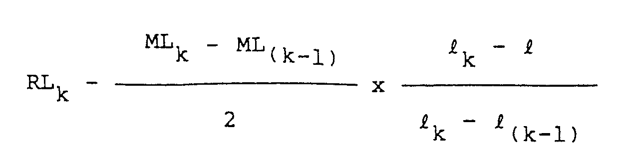
[0009] Preferably, the fine-weather reception field strength is given by:
where, k = an integer variable including a unity value for identifying the zones;
ℓ = distance between the node station and each of the substations;
ℓk = distance from each end of each radio link to a boundary between (k-1)th zone and k-th zone;
ℓ(k-1) = a distance from each end of each radio link to a boundary between (k-2)th zone and (k-1)th zone;
RLk = fine-weather reception field strength measured at distance ℓk if transmission power level of each of the two-way radio link is at maximum;
ML(k-1) = difference between the fine-weather reception field strength at distance ℓ(k-1) and tolerable rainfall reception field strength thereat; and
MLk = difference between the fine-weather reception field strength at distance ℓk and tolerable rainfall reception field strength thereat.
BRIEF DESCRIPTION OF THE DRAWINGS
[0010] The present invention will be described in further detail with reference to the accompanying drawings, in which:
Fig. 1 is a schematic illustration of a covering area of a radio communications system;
Fig. 2 is a block diagram of the radio communications system; and
Fig. 3 is a graphic representation of the reception field strength characteristic at each substation in comparison with a corresponding characteristic of a prior art system.
DETAILED DESCRIPTION
[0011] In Fig. 1, a radio communications system embodying the present invention is schematically illustrated. The system comprises a node station 1 and substations 2a, 2b and 2c within a covering area. The covering area is divided into a central zone 3 and a plurality of concentric ring zones 4. For purpose of simplicity, only two zones are illustrated. Node station 1 is located at the center of central zone 3 and substations 2a and 2b are located in the outer zone 4, but spaced apart a sufficient distance from each other to permit the use of a common frequency pair to establish individual radio links without interference. Substation 2c is located within the center zone 3, but close to the substation 2b. The center zone 3 has a radius ℓ₁ and the outer zone has a radius ℓ₂ twice as greater than radius ℓ₁. Each zone is assigned a pair of particular frequencies, one for the node station and the other for the substations in that zone. In the illustrated embodiment, two frequenciy pairs f₁ and f₂ are assigned respectively to zones 3 and 4. Node station 1 establishes pairs of two-way radio links respectively to substations 2a and 2b on frequency pair f2 and a pair of two-way radio links to substation 2c on frequency pair f₁. With this per-zone frequency assignment, the desired-to-undesired signal (D/U) ratio of each node-to-substation radio link during precipitation can be reduced to one-half of the worst D/U value of a system which employs a single frequency pair for all zones.
[0012] As shown in Fig. 2, node station 1 includes a plurality of transceiver units 1a, 1b and 1c associated respectively with substations 2a, 2b and 2c. Each node station transceiver unit comprises a transmitter 10 which modulates a carrier of a particular frequency with a baseband signal, a span attenuator 11 which couples the output of the transmitter 10 through a duplexer 12 to a parabolic antenna 13. Radio signal received by the antenna 13 is passed through the duplexer 12 to a receiver 14 which it is demodulated to a baseband signal. Node station transceiver units 1a and 1b are assigned transmit frequencies f₂' for establishing radio links with substations 2a and 2c located in the frequency-f₂-zone 4 and node station unit 1c is assigned a frequency f₁' for establishing a radio link with substation 2c located in the frequency-f₁-zone 3. Each of the substations is of identical construction to each transceiver unit of the node station. Substations 2a and 2b are assigned a frequency f₂'' to establish radio links with the transceiver units 1a and 1b of the node station and substation 2c is assigned a frequency f₁'' to establish a link with the transceiver unit 1c of the node station. Frequencies f₁' and f₁'' form a frequency pair for the central zone 3 and frequencies f₂' and f₂'' form another frequency pair for outer zone 4.
[0013] To minimize the variation of the D/U value, the span attenuator 11 at each station is adjusted to give the following relation for the central zone 3:
and the following relation for the outer zone 4:
where, ℓ = length of each radio link;
RL = fine-weather reception field strength measured in dBm at distance ℓ (see Fig. 3);
RL₁ = fine-weather reception field strength measured in dBm at distance ℓ₁ with the transmission power level of each radio link being adjusted to maximum;
RL₂ = fine-weather reception field strength measured in dBm at distance ℓ₂ with the transmission power level of each radio link being adjusted to maximum;
ML₁ = tolerable loss, or a difference between the fine-weather reception field strength and tolerable rainfall reception field strength at distance ℓ₁ from each end of each radio link; and
ML₂ = tolerable loss, or a difference between the fine-weather reception field strength and tolerable rainfall reception field strength at distance ℓ₂ from each end of each link.
[0014] Equations 1 and 2 follow a reception field-strength characteristic as indicated at 20 in Fig. 3 which shows that the reception field strength at each substation of the system increases linearly as a function of distance from the node station. The attenuator of each transceiver at the node station 1 is adjusted so that the field strength of the corresponding substation satisfies Equation 1 or 2. In this way, the fine-weather D/U value of a radio link established between the node station and the nearest of the substations in a given zone is likely to suffer most from interference by the farthest substation of the same zone and the rainfall D/U value of a radio link between the node station and the farthest of the substations of a given zone is likely to suffer most from interference by the nearest substation of the same zone. With the field-strength adjustment just described, the D/U value of each radio link from the node to each substation varies in a range one-half the range of D/U variations of the node-to-substation link in the prior art method in which the field strength is usually adjusted at a constant value regardless of the distance from the node station.
[0015] The same field-strength adjustment is performed at each substation with respect to its sub-to-node station radio link using the substation span attenuator 11, so that the reception field strength at the node station end of the sub-to-node station link satisfies the linear Equation described above and a similar characteristic to that shown in Fig. 3 can be obtained at the node station with respect to each substation. The D/U value of the sub-to-node station radio link thus varies in a range one-half of the D/U variation range of the corresponding link of the prior art system.
[0016] A total variation of the D/U value of the present invention can therefore be reduced to 1/4 of the prior art D/U variation. Since the node-station field strength of a signal from an undesired substation is also determined by the side-lobe sensitivity of an antenna of the node station and since the sensitivity of the antenna is nonlinear as a function of the azimuth angle, the 1/4 reduction of the D/U ratio variation represents a reduction of the minimum azimuth angle between adjacent substations as viewed from the node station by a factor of 1/6 to 1/10 of the prior art minimum azimuth angle. Therefore, the number of substations that can be accommodated in a radio communications system of the type as discussed above can be increased by a factor of 6 to 10.
1. A radio communications system for covering an area which is divided into concentric
zones each being assigned a pair of different frequencies (f₁', f₁''; f₂', f₂'') or
different polarizations, comprising a node station (1) centrally located in said area
and a plurality of substations (2a, 2b, 2c) having respective transceivers and located
in the divided zones, characterized in that said node station (1) includes a plurality of directional antennas (13a,
13b, 13c) corresponding respectively to said remote substations (2a, 2b, 2c) for simultaneously
establishing a plurality of two-way, point-to-point radio links respectively with
the substations (2a, 2b, 2c), and in that the node station (1) and said substations
(2a, 2b, 2c) have a fine-weather reception field at each of the respective radio links
such that the reception field strength of longer radio links is greater than the reception
field strength of shorter radio links, there being a linear relationship between the
reception field strength of each radio link and the length of the radio link.
2. A radio communication system as claimed in claim 1, wherein said fine-weather reception
field strength is given by:
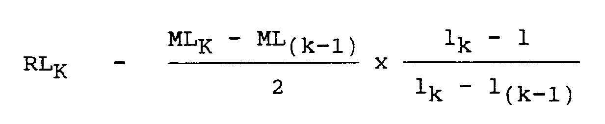
where, k = an integer variable including a unity value for identifying said zones;
ℓ = distance between said node station and each of said substations;
ℓk = distance from each end of each said radio link to a boundary between (k-1)th zone and k-th zone;
ℓ(k-1) = a distance from each end of each said radio link to a boundary between (k-2)th zone and (k-1)th zone;
RLk = fine-weather reception field strength measured at distance ℓk if transmission power of each of said two-way radio link is at maximum;
ML(k-1) = difference between the fine-weather reception field strength at distance ℓ(k-1) and tolerable rainfall reception field strength thereat; and
MLk = difference between the fine-weather reception field strength at distance ℓk and tolerable rainfall reception field strength thereat.
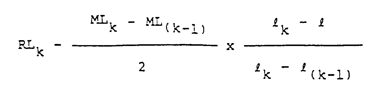
1. Funkkommunikationssystem zum Überdecken eines Bereichs, der in konzentrische Zonen
unterteilt ist, denen jeweils ein Paar verschiedener Frequenzen (f₁', f₁''; f₂', f₂'')
oder verschiedener Polarisationsebenen zugewiesen sind, mit einer im Bereich zentral
angeordneten Knotenstation (1) und mehreren in den unterteilten Zonen angeordneten
Unterstationen (2a, 2b, 2c) mit jeweiligen Sender-Empfängern,
dadurch gekennzeichnet, daß
die Knotenstation (1) mehrere Richtantennen (13a, 13b, 13c) aufweist, die jeweils den entfernt angeordneten Unterstationen (2a, 2b, 2c) zugeordnet sind, zum gleichzeitigen Errichten mehrerer Zweiweg-Punkt-zu-Punkt-Richtfunkstrecken zu den jeweiligen Unterstationen (2a, 2b, 2c), und die Knotenstation (1) sowie die Unterstationen (2a, 2b, 2c) eine derartige Schönwetter-Empfangsfeldstärke an jeder der Richtfunkstrecken aufweisen, daß die Empfangsfeldstärke längerer Richtfunkstrecken größer ist als die Empfangsfeldstärke kürzerer Richtfunkstrecken, wobei zwischen der Empfangsfeldstärke jeder Richtfunkstrecke und der Länge der Richtfunkstrecke ein linearer Zusammenhang besteht.
2. Funkkommunikationssystem nach Anspruch 1, wobei die Schönwetter-Empfangsfeldstärke
gegeben ist durch
wobei k = ganzzahlige Variable, die einen Einheitswert zum Identifizieren der Zonen enthält;
l = Abstand zwischen der Knotenstation und jeder der Unterstationen;
lk = Abstand von jedem Ende jeder Richtfunkstrecke zu einer Grenze zwischen der (k-1)-ten und der k-ten Zone;
l(k-1) = Abstand von jedem Ende jeder Richtfunkstrecke zu einer Grenze zwischen der (k-2)-ten Zone und der (k-1)-ten Zone;
RLk = Schönwetter-Empfangsfeldstärke, die bei einem Abstand lk gemessen wird, wenn der Sendeleistungspegel jeder Zweiweg-Richtfunkstrecke maximal ist;
ML(k-1) = Differenz zwischen der Schönwetter-Empfangsfeldstärke beim Abstand l(k-1) und der dort zulässigen Niederschlag-Empfangsfeldstärke; und
MLk = Differenz zwischen der Schönwetter-Empfangsfeldstärke beim Abstand lk und der dort zulässigen Niederschlag-Empfangsfeldstärke.
1. Système de radiocommunication permettant la couverture d'une région qui est divisée
en zones concentriques chacune de ces zones ayant affecté une paire de fréquences
différentes (f₁', f₁'' ; f₂', f₂'') ou de polarisations différentes, comprenant une
station de noeud (1) placée au centre de la région et une multitude de sous-stations
(2a, 2b, 2c) ayant des émetteurs/récepteurs respectifs et placées dans les zones divisées,
caractérisé en ce que la station de noeud (1) comporte une multitude d'antennes directionnelles
(13a, 13b, 13c) correspondant respectivement aux sous-stations distantes (2a, 2b,
2c) afin d'établir simultanément une multitude de liaisons radio point-à-point, bidirectionnelles
respectivement avec les sous-stations (2a, 2b, 2c), et en ce que la station de noeud
(1) et les sous-stations (2a, 2b, 2c) ont un champ de réception météorologique fin
à chacune des liaisons radio respectives de sorte que l'intensité du champ de réception
des liaisons radio les plus longues soit supérieure à l'intensité du champ de réception
des liaisons radio les plus courtes, et il existe une relation linéaire entre l'intensité
du champ de réception de chaque liaison radio et la longueur de la liaison radio.
2. Système de radiocommunication selon la revendication 1, dans lequel ladite intensité
du champ de réception météorologique fin est donnée par :
où k est un nombre entier variable comprenant une valeur unitaire pour identifier lesdites zones,
ℓ est la distance entre la station de noeud et chacune des sous-stations;
ℓk est la distance entre chaque extrémité de chaque liaison radio et la frontière entre la (k-1)ème zone et la kème zone;
ℓ(k-1) est la distance entre chaque extrémité de chaque liaison radio et la frontière entre la (k-2)ème zone et la (k-1)ème zone;
RLk est l'intensité du champ de réception météorologique fin mesurée à la distance ℓk si la puissance de transmission de chacune desdites liaisons radio bidirectionnelles est au maximum;
ML(k-1) est la différence entre l'intensité du champ de réception météorologique fin à la distance ℓ(k-1) et l'intensité du champ de réception tolérable des précipitations à cette distance et
MLk est la différence entre l'intensité du champ de réception météorologique fin à la distance ℓk et l'intensité du champ de réception tolérable des précipitations à cette distance.