|
(11) | EP 0 336 616 B1 |

| (12) | EUROPEAN PATENT SPECIFICATION |
|
|
| (54) |
Compatible optical disk Kompatible optische Platte Disque optique compatible |
|
|
|||||||||||||||||||||||||||||||
| Note: Within nine months from the publication of the mention of the grant of the European patent, any person may give notice to the European Patent Office of opposition to the European patent granted. Notice of opposition shall be filed in a written reasoned statement. It shall not be deemed to have been filed until the opposition fee has been paid. (Art. 99(1) European Patent Convention). |
[0001] The present invention relates to a compatible optical disk. Namely, the present invention relates to a rewritable optical disk compatible with a compact disk (CD) used exclusively for reproduction. More particularly, the present invention relates to an optical disk in which information can be reproduced by using a commercially available standard CD player and writing, rewriting, and erasure can be performed.
(2) Description Related Art
[0002] Compact disks are industrially valuable because they enable users to easily utilize large information (voices, images and the like) capacities normally used exclusively for reproduction, at a low cost. Nevertheless, where writing, rewriting, or a partial change of information is desired, a new original disk must be prepared, and this incurs much expense and time. Accordingly, if a CD used exclusively for reproduction can be made writable or rewritable, and a conventional player normally used exclusively for reproduction can be used for a reproduction of information stored in this disk, a valuable contribution to society can be made since CD players already widely available can be effectively utilized.
[0003] Rewritable optical disks and additional write type optical disks in which information can be only recorded have been intensively investigated, and disks of this type have been marketed.
[0004] In disks of this type, however, to increase the recording sensitivity, the absorption of light is enhanced, and thus the reflectivity is kept to a low level, and accordingly, information cannot be read out by commercially available CD players. Namely, a reflectivity of at least 70% is stipulated as the standard value for a CD used exclusively for reproduction, and players are constructed to comply with this standard, but the reflectivity of rewritable optical disks or additional write type optical disks is generally as low as 15 to 50%. Furthermore, additional write type optical disks are usually perforation type, i.e., holes are formed in the recorded areas, and accordingly, the reflectivity is almost 0% in the recorded areas. Therefore, the reflectivity in the recorded area is lower than the reflectivity before the recording, and for this reason also, reproduction by CD players is impossible.
[0005] To provide a compatible writable or rewritable optical disk in which reproduction is possible by a standard CD player, the reflectivity of the disk must be increased, but this increase of the reflectivity results in a reduction of the recording sensitivity.
[0006] Furthermore, to perform the recording, the recording beams must be positioned in the form of tracks at a predetermined part of the disk. If information is already recorded, it is possible for information tracks to be traced, but if the disk is unrecorded and has no specific structure, it is very difficult to position tracks for the recording, and a guidance structure is required.
[0007] Usually, a groove is used as the guidance structure, and the shape of the guide groove must satisfy certain conditions. For example, where a signal is recorded along a trough portion, a condition represented by the following inequality must be satisfied:
If this condition (1) is not satisfied, for a CD player wherein a 3-beam tracking system is adopted, light beams trace the crest portion and the signal cannot be reproduced. To satisfy the condition (1), the width of the trough portion must be narrowed, but if the width of the trough portion is narrowed, the amplitude of the signal is reduced and the CN ratio (carrier/noise ratio) is reduced.
[0008] EP-A-0132137 discloses a writable optical disk. The disk includes a transparent substrate and a light beam-guiding groove is formed on the substrate. A thin light-absorbing film is formed on the surface of the substrate. Information is recorded by irradiating the film in the trough of the groove. After recording, the reflectivity of the film in the crest of the groove and in the trough of the groove are increased.
[0009] According to the present invention, the above problems are solved by using a recording material which is characterized in that the reflectivity of the disk in an unrecorded state is lower than 50%, and when recording is effected by an irradiation of light, the reflectivity of the irradiated area of the recording film is increased. As a material having such properties, a phase transition type InSb alloy crystal film can be used, for example. Furthermore, a film can be used in which fine convexities and concavities are preformed, the reflectivity is reduced in an unrecorded state by scattering on the convexities and concavities, but by irradiation with light, the convexities and concavities are flattened to increase the reflectivity. More specifically, a light beam-guiding groove, for example, one spiral groove, is formed on a disk substrate so that information is recorded or read out along the crest portion of this guiding groove, and the reflectivity of the trough portion between the troughs crests is enhanced.
[0010] More specifically, in accordance with the present invention, there is provided a compatible writable optical disk in which information is written, the optical disk comprising a transparent substrate, a light beam-guiding groove formed on one surface of the substrate and a recording film or a multi-layer film including a recording film, formed on the groove-formed surface of the substrate, wherein information can be recorded, erased or reproduced by irradiation of light beams along a trough portion or crest portion of the groove; the reflectivity of the recording film is capable of being changed by irradiation of light to record or erase information; the reflectivity of the optical disk observed from the side of the transparent substrate being lower than 50% in an unrecorded state and the reflectivity being increased when a recorded state is produced by irradiation with light; characterised in that the reflectivity is locally increased by recording information along the crest portion, and the reflectivity of the trough portion is enhanced, so that the average reflectivity of the information-recorded crest portion over the length of the groove is not higher than the reflectivity of the trough portion between the crests averaged over the length of the groove, when the reflectivity is observed by an optical head.
[0011] Particular embodiments of optical disks in accordance with this invention will now be described and contrasted with the prior art with reference to the accompanying drawings; in which:-
Figures 1A and 1B are a cross-section and plan respectively;
Figure 2 is partially enlarged section;
Figure 3 is a block diagram of an apparatus recording information;
Figure 4 is a perspective view of the optical disk; and;
Figure 5 is a diagram of a conventional CD used exclusively for reproduction.
[0012] According to the CD standard, the light beam-guiding groove comprises one spiral groove, and the direction of rotation is counterclockwise from the inner circumference to the periphery, seen from the side of the groove-formed surface. In the present invention, the pitch of the light beam-guiding groove is 1.5 to 2.0 µm, preferably 1.6 to 2.0 µm, the depth of the trough portion of the groove is 0.03 to 0.11 µm, preferably 0.03 to 0.06 µm, and the width of the trough portion or crest portion of the groove is 0.5 to 1.0 µm, preferably 0.7 to 1.0 µm. Preferably, the crest portion between the troughs is flat.
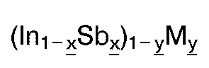
[0013] As a preferred example of the recording film used in the present invention, there can be mentioned a crystal film of an alloy represented by the following formula:
wherein x is a number of 0.5 ≦ x ≦ 0.7 (atomic ratio), y is a number of 0 ≦ y ≦ 0.2 (atomic ratio), and M is at least one member selected from the group consisting of Al, Si, P, Zn, Ga, Ce, As, Se, Ag, Cd, Sn, Te, Tl, Bi, Pb, Mo, Ti, Co, Ni, W, Au, Ge, and Pt.
[0014] According to the present invention using the above-mentioned material in which the reflectivity is increased by the recording, where the recording is carried out along the trough portion, the reflectivity is increased in the crest portion and at bits of the trough portion; or where the recording is carried out along the crest portion, the reflectivity is increased in the trough portion and at bits of the crest portion. Accordingly, a reflectivity (average reflectivity over the entire disk) enabling the use of a commercially available CD player is obtained. If the groove width is increased to solve the problem of reduction of the CN ratio caused when the groove width is narrowed, it is impossible to satisfy the above-mentioned condition (1). In this case, this disadvantage can be eliminated by increasing the reflectivity of the crest portion, and thus condition (1) can be satisfied.
[0015] Accordingly, in the present invention, even if the reflectivity is low in an unrecorded or erased state, no problems arise, and the present invention is advantageous in that the range of selection of the material of the recording film is broadened.
[0016] Moreover, since the condition (1) is satisfied, a satisfactory tracking error signal can be obtained even by a three-beam head, and therefore, signals can be read out by a stable tracking using a commercially available CD player.
[0017] According to the present invention, there is provided an optical disk in which information can be read out by a CD player in the same manner as from a conventional CD used exclusively for reproduction, moreover the optical disk is rewritable. Accordingly, in the disk of the present invention, rewriting can be easily accomplished as required, and the disk of the present invention is easy to use and is inexpensive. Therefore, the practical and industrial importance of the present invention is high.
[0018] The present invention will now be described in detail with reference to the following examples.
Embodiment 1
[0019] Figure 1 illustrates a compatible rewritable optical disk according to one embodiment of the present invention, and Fig. 2 is a partially enlarged sectional view of the disk shown in Fig. 1. The disk (substrate) 11 has a shape specified by the CD standard, i.e., a thickness of 1.2 mm, an outer diameter of 120 mm, and an inner hole diameter of 15 mm. In a disk to be used exclusively for reproduction, in general, as shown in Fig. 5, many information pits 2 formed on the surface of a substrate 1 are spirally connected to one another, and a reflecting film 3 of aluminum covers the pit-formed surface. The disk of the present embodiment is different from this conventional disk in that one spiral groove 12 is formed instead of the pits 2; the turning pitch of the groove 12 being 1.6 µm, and the direction of rotation of the spiral being counterclockwise from the inner circumference to the periphery, seen from the side of the surface at which the groove 12 is present. The groove 12 has a depth of 0.05 µm and a width of 0.7 µm, and the portion other than the groove, i.e., the crest portion, is flat.
[0020] A recording film 13 is formed on the grooved substrate 11, and a protecting film 14 is formed on the recording film 13. The recording film 13 is, for example, an alloy crystal film obtained by a vacuum deposition of In and Sb, which comprises 45 atomic % of In and 55 atomic % of Sb. The protecting film 14 is formed, for example, by coating and curing a UV-curable resin, and the thickness of the protecting film 14 is 50 µm.
[0021] The initial reflectivity of the disk is about 40% in the flat portion of the disk, but if the disk is irradiated with strong laser beam pulses for a short time, the reflectivity is increased to about 60%. If the recording film 13 is irradiated in this state with relatively weak laser beams, the reflectivity is again reduced to the initial value of 40%. Accordingly, if the high-reflectivity state is used for recording and the low-reflectivity state is used for erasure, information can be repeatedly rewritten.
[0022] If a third element is incorporated into the InSb alloy crystal film, valuable as the recording film, other characteristics thereof can be improved without degradation of the reflectivity or rewritability. For example, the long-term storage of information can be improved by an addition of Se, Si, Ge, Te, Tl, Al, As or Sn, and an increase of the rewriting times can be obtained by an incorporation of P, Zn, As, Cd, Ag, Ti, Au, Pd, Pt, Sn, Pb, Ga, Mo or W. Furthermore, an improvement of the recording and erasure sensitivity can be obtained by an incorporation of Al, Bi, Cd, Pb or Ga.
[0023] InSb alloy type crystal films, and similar crystal recording films valuable as a material for recording information by changing the crystal state by an irradiation of light, and thus changing the reflectivity, are disclosed by Japanese Patent Application No. 59-255672, No. 59-255673, No. 59-274502, No. 59-274537, No. 60-6669, No. 60-6670, No. 60-6671 and No. 60-67983.
[0024] In those inventions, the disk is rotated at a linear velocity of 5 m/sec, and direct-current (dc) laser beams are applied along the crest portion of the disk on the disk surface at a power of 10 mW by using an optical head; the beam diameter being smaller than 1 µm. The reflectivity in the crest portion is increased by about 1.5 times that of the level before irradiation, and the reflectivity of the trough portion of the groove is not changed. Information is recorded at the trough portion 12 in the disk having an increased or enhanced reflectivity at the crest portion.
[0025] Figure 3 illustrates the structure of an apparatus for recording information or renewing recorded information with new information in the compatible rewritable optical disk of the present invention. Information 21 in 8-bit units to be recorded is subjected to the signal transformation (ECC or modulation) 22 stipulated by the standard and output to a recording drive 23, which is substantially the same as the recording drive of the conventional additional write type apparatus. Namely, semiconductor laser beams converged to a beam diameter smaller than 1 µm are applied along the spiral groove to record the information in the recording film. At this step, known means such as a tracking servo 24, a focus servo 25, and a rotational servo 26 are used. The speed of rotation of the disk is controlled in accordance with the radial position of the irradiation, to obtain a constant linear velocity (CLV) of, for example, 1.2 to 1.4 m/sec.
[0026] The intensity of the semiconductor laser is modulated according to the information signals, and the peak power is kept within 5 to 10 mW. The reflectivity is increased in the area irradiated with a high output power of laser beam, and accordingly, high reflectivity areas and low reflectivity area are formed, and the information is recorded.
[0027] Figure 4 shows the state of recording or reproduction of information in the compatible rewritable optical disk of the present invention. In Fig. 4, the substrate 11, guide groove 12, and recording film 13 are the same as those shown in Fig. 2, 15 represents laser beams and 16 represents an information-recorded reflectivity-increased portion of the recording film 13. Reference numeral 17 represents the crest portion having the same state as the recorded portion 16 in the guide groove 12 and an increased reflectivity.
[0028] In the disk in which the reflectivity is increased in the crest portion 17 and information is recorded in a predetermined format in the groove 12, the information can be reproduced even by a commercially available player used exclusively for reproduction. Namely, this disk is compatible. In this case, the problem is whether or not the servo focussing and servo tracking can be accomplished stably. In the disk having an increased reflectivity, according to the present invention, the problem of the magnitude of the focus error signal does not arise, and therefore, focussing can be performed without trouble by any commercially available player.
[0029] While for tracking, since two tracking systems are available, a practical test should be carried out for each system.
[0030] The first system is a push-pull system in which a tracking signal is obtained by utilizing light diffracted from a pit. This pit has substantially the same function as the groove formed on the disk of the present invention. As an example of this system, there can be mentioned a CD player, CD-1100SD1 supplied by Fujitsu-Ten, and when the disk of the present invention is mounted on this apparatus, voice information can be stably reproduced.
[0031] The second system is a three-beam system in which the optical beam is divided into three beams, information signals are read by the central beam, and tracking signals are taken in by the two beams on both sides. As an example of this system, there can be mentioned CDP-550-ESD supplied by Sony. When the disk of the present invention is mounted on this apparatus, voice information can be stably read out.
[0032] In contrast, in a disk in which the reflectivity of the crest portion is not enhanced, the condition (1) is not satisfied, and a stable read-out is impossible.
[0034] The recorded disk of the present invention is mounted on the write-erase machine, and beams are applied along the information track under tracking, focussing and rotational servo (CLV) procedures as in the first recording. At this step, the recorded information track (groove 12) is irradiated by dc laser beams having a peak power corresponding to 40 to 60% of the peak power at the recording procedure, whereby the reflectivity of the information track 12 is uniformly returned to the low level and the recorded information can be completely erased.
[0035] At this point, the reflectivity of the crest portion remains high and is at the same level as the level before the erasure. Therefore, new information can be recorded on the disk in the same manner as described above. Namely, rewriting can be performed.
Embodiment 2
[0036] The same substrate as used in Example 1 is prepared, and an In₄₅Sb₅₅ alloy crystal film is vacuum-deposited on the substrate.
[0037] The disk is then mounted on a recording apparatus, and the surface of the disk is irradiated by dc laser beams having a power of 10 mW, along the groove 12 (trough portion) while maintaining a linear velocity of 5 m/sec.
[0038] The disk is then placed in a sputtering apparatus, and reverse sputtering is carried out under an argon gas pressure of 0.2 Pa at the RF power of 200 W, for 5 minutes, whereby portions not irradiated by the laser beams, i.e., the crest portion 17 or the flat portion on which the groove is not formed, are etched. Namely, the In-Sb alloy film remains only in the trough portion. Silicon dioxide is then deposited by sputtering to a thickness of 100 nm, and subsequently, aluminum is deposited to a thickness of 40 nm.
[0039] The disk was removed from the sputtering apparatus, and an examination of the reflectivity by an optical head, confirmed that the reflectivity of the flat portion was 75%. At this time, the In-Sb film of the trough portion 12 was in the recorded state, and the condition (1) is satisfied in the disk. When the disk is irradiated with dc beams having a power of 4 mW at a linear velocity of 1.4 m/sec, the In-Sb alloy film of the trough portion is returned to the erasure state. The protecting film 14 may be formed on the aluminum layer as mentioned above.
1. A compatible writable optical disk in which information is written, the optical disk
comprising a transparent substrate (11), a light beam-guiding groove (12) formed on
one surface of the substrate and a recording film (13) or a multi-layer film including
a recording film, formed on the groove-formed surface of the substrate, wherein information
can be recorded, erased or reproduced by irradiation of light beams along a trough
portion (12) or crest portion (17) of the groove; the reflectivity of the recording
film (13) is capable of being changed by irradiation of light to record or erase information;
the reflectivity of the optical disk observed from the side of the transparent substrate
being lower than 50% in an unrecorded state and the reflectivity being increased when
a recorded state is produced by irradiation with light; characterised in that the
reflectivity is locally increased by recording information along the crest portion
(17), and the reflectivity of the trough portion (12) is enhanced, so that the average
reflectivity of the information-recorded crest portion (17) over the length of the
groove is not higher than the reflectivity of the trough portion (12) between the
crests averaged over the length of the groove, when the reflectivity is observed by
an optical head.
2. An optical disk according to claim 1, wherein the light beam-guiding groove (12) is
formed by a single spiral groove.
3. An optical disk according to anyone of the preceding claims, wherein a phase transformation
type material is used for the recording film, and its crystal state is changed by
irradiation of light to change the reflectivity and this change is used for recording
or erasing information.
4. An optical disk according to claim 3, wherein the reflectivity of the trough portion
(12) is enhanced by removing the recording film of the trough portion (12) by etching,
followed by forming a reflecting film of aluminum or gold.
5. An optical disk according to any of the preceding where in the trough portion (12)
is kept in a recorded state to enhance the reflectivity at the trough portion.
6. An optical disk according to claim 5, wherein the trough portion (12) is brought to
a recorded state by a direct-current irradiation of light beams.
7. An optical disk according to any one of the preceding claims, wherein the recording
film is a film of an alloy represented by the following formula:
wherein x is a number defined by the inequality 0.5 ≦ x ≦ 0.7, y is a number defined by the inequality O ≦ y ≦ 0.2, and M is at least one element selected from a group consisting of Al, Si, P, Zn, Ga, Ce, As, Se, Ag, Cd, Sn, Te, Tl, Bi, Pb, Mo, Ti, W, Au, Pt, Co, Ni, and Ge.
wherein x is a number defined by the inequality 0.5 ≦ x ≦ 0.7, y is a number defined by the inequality O ≦ y ≦ 0.2, and M is at least one element selected from a group consisting of Al, Si, P, Zn, Ga, Ce, As, Se, Ag, Cd, Sn, Te, Tl, Bi, Pb, Mo, Ti, W, Au, Pt, Co, Ni, and Ge.
8. An optical disk according to any one of the preceding claims, wherein the reflectivity
of the crest portion (17) of the substrate in an unrecorded state is 10 to 45%.
9. An optical disk according to any one of the preceding claims, wherein the pitch of
the light beam-guiding groove is 1.5 to 2.0 µm.
10. An optical disk according to any one of the preceding claims, wherein the depth of
the trough portion (12) of the groove is 0.03 to 0.11 µm.
11. An optical disk according to any one of the preceding claims, wherein the width of
the trough portion (12) or crest portion (17) of the groove is from 0.5 to 1.0 µm.
1. Kompatible beschreibbare optische Platte, in welche Informationen geschrieben werden,
welche optische Platte ein transparentes Substrat (11), eine Lichtstrahl-Führungsrille
(12), die auf einer Fläche des Substrats gebildet ist, und einen Aufzeichnungsfilm
(13) oder einen einen Aufzeichnungsfilm enthaltenden mehrschichtigen Film, der auf
der mit der Rille versehenen Fläche des Substrats gebildet ist, in dem Informationen
durch die Einstrahlung von Lichtstrahlen entlang einem Vertiefungsteil (12) oder Erhebungsteil
(17) der Rille aufgezeichnet, gelöscht oder wiedergegeben werden können, umfaßt; wobei
das Reflexionsvermögen des Aufzeichnungsfilms (13) durch die Einstrahlung von Licht
zum Aufzeichnen oder Löschen von Informationen geändert werden kann; wobei das Reflexionsvermögen
der optischen Platte, von der Seite des transparenten Substrats gesehen, in einem
unbeschriebenen Zustand weniger als 50 % beträgt, und das Reflexionsvermögen erhöht
wird, wenn durch Einstrahlung von Licht ein beschriebener Zustand erzeugt wird; dadurch
gekennzeichnet, daß das Reflexionsvermögen durch die Aufzeichnung von Informationen
entlang dem Erhebungsteil (17) lokal erhöht wird, und das Reflexionsvermögen des Vertiefungsteils
(12) verstärkt wird, so daß das mittlere Reflexionsvermögen des mit Informationen
beschriebenen Erhebungsteils (17) über die Länge der Rille nicht höher ist als das
Reflexionsvermögen des Vertiefungsteils (12) zwischen den Erhebungen, gemittelt über
die Länge der Rille, wenn das Reflexionsvermögen von einem optischen Kopf ermittelt
wird.
2. Optische Platte nach Anspruch 1, bei welcher die Lichtstrahl-Führungsrille (12) durch
eine einzige spiralförmige Rille gebildet wird.
3. Optische Platte nach einem der vorhergehenden Ansprüche, bei welcher ein Material
vom Phasentransformationstyp für den Aufzeichnungsfilm verwendet wird, und sein Kristallzustand
durch die Einstrahlung von Licht geändert wird, um das Reflexionsvermögen zu ändern,
und diese Änderung zum Aufzeichnen oder Löschen von Informationen eingesetzt wird.
4. Optische Platte nach Anspruch 3, bei welcher das Reflexionsvermögen des Vertiefungsteils
(12) durch die Entfernung des Aufzeichnungsfilms des Vertiefungsteils (12) durch Ätzen,
gefolgt von der Bildung eines Reflexionsfilms aus Aluminium oder Gold, verstärkt wird.
5. Optische Platte nach einem der vorhergehenden Ansprüche, bei welcher der Vertiefungsteil
(12) in einem beschriebenen Zustand gehalten wird, um das Reflexionsvermögen am Vertiefungsteil
zu verstärken.
6. Optische Platte nach Anspruch 5, bei welcher der Vertiefungsteil (12) durch eine Gleichstrom-Einstrahlung
von Lichtstrahlen in einen beschriebenen Zustand gebracht wird.
7. Optische Platte nach einem der vorhergehenden Ansprüche, bei welcher der Aufzeichnungsfilm
ein Film einer Legierung der folgenden Formel ist:

worin x eine durch die Ungleichheit 0,5 ≦ x ≦ 0,7 definierte Zahl ist, y eine durch die Ungleichheit 0 ≦ y ≦ 0,2 definierte Zahl ist, und M zumindest ein Element ausgewählt aus einer Gruppe bestehend aus Al, Si, P, Zn, Ga, Ce, As, Se, Ag, Cd, Sn, Te, Tl, Bi, Pb, Mo, Ti, W, Au, Pt, Co, Ni und Ge bedeutet.
worin x eine durch die Ungleichheit 0,5 ≦ x ≦ 0,7 definierte Zahl ist, y eine durch die Ungleichheit 0 ≦ y ≦ 0,2 definierte Zahl ist, und M zumindest ein Element ausgewählt aus einer Gruppe bestehend aus Al, Si, P, Zn, Ga, Ce, As, Se, Ag, Cd, Sn, Te, Tl, Bi, Pb, Mo, Ti, W, Au, Pt, Co, Ni und Ge bedeutet.
8. Optische Platte nach einem der vorhergehenden Ansprüche, bei welcher das Reflexionsvermögen
des Erhebungsteils (17) des Substrats in einem unbeschriebenen Zustand 10 bis 45 %
beträgt.
9. Optische Platte nach einem der vorhergehenden Ansprüche, bei welcher der Abstand oder
die Steigung der Lichtstrahl-Führungsrille 1,5 bis 2,0 µm beträgt.
10. Optische Platte nach einem der vorhergehenden Ansprüche, bei welcher die Tiefe des
Vertiefungsteils (12) der Rille 0,03 bis 0,11 µm beträgt.
11. Optische Platte nach einem der vorhergehenden Ansprüche, bei welcher die Breite des
Vertiefungsteils (12) oder des Erhebungsteils (17) der Rille 0,5 bis 1,0 µm beträgt.
1. Disque optique compatible inscriptible dans lequel des informations sont écrites,
le disque optique comportant un substrat transparent (11), une gorge (12) de guidage
d'un faisceau lumineux, formée sur une surface du substrat, et un film (13) d'enregistrement
ou un film multicouche comprenant un film d'enregistrement, formé à la surface du
substrat ayant la gorge, si bien que des informations peuvent être enregistrées, effacées
ou lues par projection de faisceaux lumineux le long d'une partie (12) de creux ou
d'une partie (17) de crête de la gorge, le pouvoir réflecteur du film d'enregistrement
(13) pouvant être changé par irradiation par la lumière afin que des informations
soient enregistrées ou effacées, le pouvoir réflecteur du disque optique, observé
du côté du substrat transparent, étant inférieur à 50 % à l'état non enregistré et
le pouvoir réflecteur étant accru lorsqu'un état enregistré est produit par projection
de lumière, caractérisé en ce que le pouvoir réflecteur est augmenté localement par
enregistrement d'informations le long de la partie de crête (17) et le pouvoir réflecteur
de la partie de creux (12) est accru, si bien que le pouvoir réflecteur moyen de la
partie de crête (17) ayant les informations enregistrées sur la longueur de la gorge
n'est pas supérieur au pouvoir réflecteur de la partie de creux (12) entre les crêtes,
en moyenne sur la longueur de la gorge, lorsque le pouvoir réflecteur est observé
avec une tête optique.
2. Disque optique selon la revendication 1, dans lequel la gorge (12) de guidage de faisceau
lumineux est formée d'une seule gorge spiralée.
3. Disque optique selon l'une quelconque des revendications précédentes, dans lequel
une matière d'un type présentant une transformation de phases est utilisée pour le
film d'enregistrement, et son état cristallin est changé par projection de lumière
destinée à modifier le pouvoir réflecteur, et ce changement est utilisé pour l'enregistrement
ou l'effacement des informations.
4. Disque optique selon la revendication 3, dans lequel le pouvoir réflecteur de la partie
de creux (12) est accru par enlèvement de film d'enregistrement de la partie de creux
(12) par attaque, puis par formation d'un film réfléchissant d'aluminium ou d'or.
5. Disque optique selon l'une quelconque des revendications précédentes, dans lequel
la partie de creux (12) est maintenue à un état enregistré afin que le pouvoir réflecteur
soit accru dans la partie de creux.
6. Disque optique selon la revendication 5, dans lequel la partie de creux (12) est mise
à un état enregistré par irradiation de faisceaux lumineux en courant continu.
7. Disque optique selon l'une quelconque des revendications précédentes, dans lequel
le film d'enregistrement est un film d'un alliage représenté par la formule suivante
:

x étant un nombre défini par l'inégalité 0,5 ≦ x ≦ 0 7, y étant un nombre défini par l'inégalité 0 ≦ y ≦ 0,2, et M étant au moins un élément choisi dans le groupe qui comprend Al, Si, P, Zn, Ga, Ce, As, Se, Ag, Cd, Sn, Te, Tl, Bi, Pb, Mo, Ti, W, Au, Pt, Co, Ni et Ge.
x étant un nombre défini par l'inégalité 0,5 ≦ x ≦ 0 7, y étant un nombre défini par l'inégalité 0 ≦ y ≦ 0,2, et M étant au moins un élément choisi dans le groupe qui comprend Al, Si, P, Zn, Ga, Ce, As, Se, Ag, Cd, Sn, Te, Tl, Bi, Pb, Mo, Ti, W, Au, Pt, Co, Ni et Ge.
8. Disque optique selon l'une quelconque des revendications précédentes, dans lequel
le pouvoir réflecteur de la partie de crête (17) du substrat, à l'état non enregistré,
est compris entre 10 et 45 %.
9. Disque optique selon l'une quelconque des revendications précédentes, dans lequel
le pas de la gorge de guidage de faisceau lumineux est compris entre 1,5 et 2,0 µm.
10. Disque optique selon l'une quelconque des revendications précédentes, dans lequel
la profondeur de la partie de creux (12) de la gorge est comprise entre 0,03 et 0,11
µm.
11. Disque optique selon l'une quelconque des revendications précédentes, dans lequel
la largeur de la partie de creux (12) ou de la partie de crête (17) de la gorge est
comprise entre 0,5 et 1,0 µm.