| (19) |
 |
|
(11) |
EP 0 596 846 A1 |
| (12) |
EUROPEAN PATENT APPLICATION |
| (43) |
Date of publication: |
|
11.05.1994 Bulletin 1994/19 |
| (22) |
Date of filing: 21.10.1993 |
|
|
| (84) |
Designated Contracting States: |
|
CH DE DK ES FR GB IT LI |
| (30) |
Priority: |
03.11.1992 SE 9203248
|
| (71) |
Applicant: AKTIEBOLAGET ELECTROLUX |
|
S-105 45 Stockholm (SE) |
|
| (72) |
Inventor: |
|
- Castwall, Lennart Wilhelm
S-18335 Täby (SE)
|
| (74) |
Representative: Erixon, Bo et al |
|
c/o AB ELECTROLUX Corporate Patents & Trademarks
105 45 Stockholm
105 45 Stockholm (SE) |
|
| |
|
(57) A kitchen ventilator comprises a housing (10) having a motor powered fan (20), an
inlet (11), an inlet passage (25) between the inlet and the fan, an outlet (17), and
an outlet passage (23) between the fan and the outlet, said passages being separated
by a generally vertical partition wall (22). The inlet passage is partially formed
by a baffle wall (26) provided between the inlet and the fan, and a removable front
wall (16) provided with a sound absorbing material, and the outlet passage (23) has
a narrowing portion (33) which is provided on both sides with sound absorbing material
(18, 19).
For reducing the noice level, the ventilator is provided with means for active silencing,
comprising an acoustic sensor (28) for sensing the noice of the fan, a loudspeaker
(30) for emitting a sound silencing the fan noice in reverse phase therewith, and
an electronic control unit (29) connected to said sensor and said loudspeaker and
adapted to control the loudspeaker in response to information received from said sensor.
|
|
[0001] The present invention relates to a kitchen ventilator comprising a housing, a motor
powered fan having a horizontal axis arranged in the bottom portion of the housing,
an inlet, an inlet passage between the inlet and the fan, an outlet, and an outlet
passage between the fan and the outlet, said passages being separated by a generally
vertical partition wall.
[0002] In order to efficiently collect fumes produced in connection with cooking a relatively
heavy air flow is required and in order to obtain this a large capacity fan is necessary.
The drawback of such a fan is that it produces a relatively heavy, disturbing noise.
[0003] The object of the invention is to reduce this problem by providing a ventilator in
which the noice level has been minimized. This has been obtained by means of a ventilator
of the kind mentioned in the introduction, which according to the invention is characterized
in that the inlet passage is formed partially by a baffle wall provided between the
inlet and the fan, and a removable front wall provided with a sound absorbing material,
said outlet passage having a narrowing portion which is provided on both sides with
sound absorbing material.
[0004] The invention will be described in more detail below with reference to the accompanying
drawings, in which
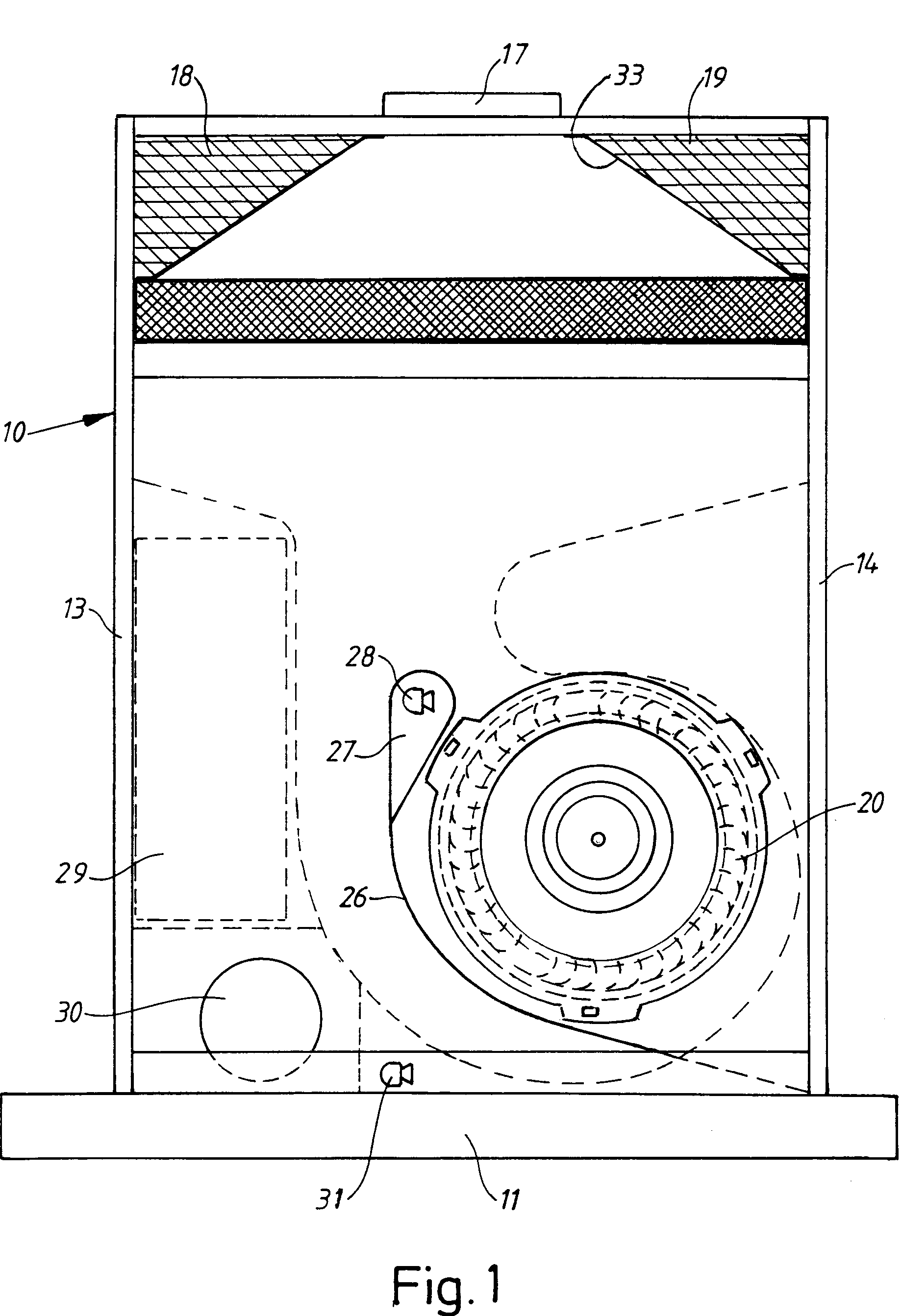
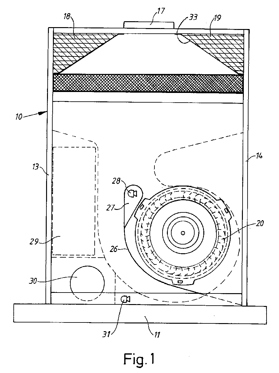
- Figure 1
- illustrates a front view of the ventilator according to the invention with the front
wall thereof removed, and
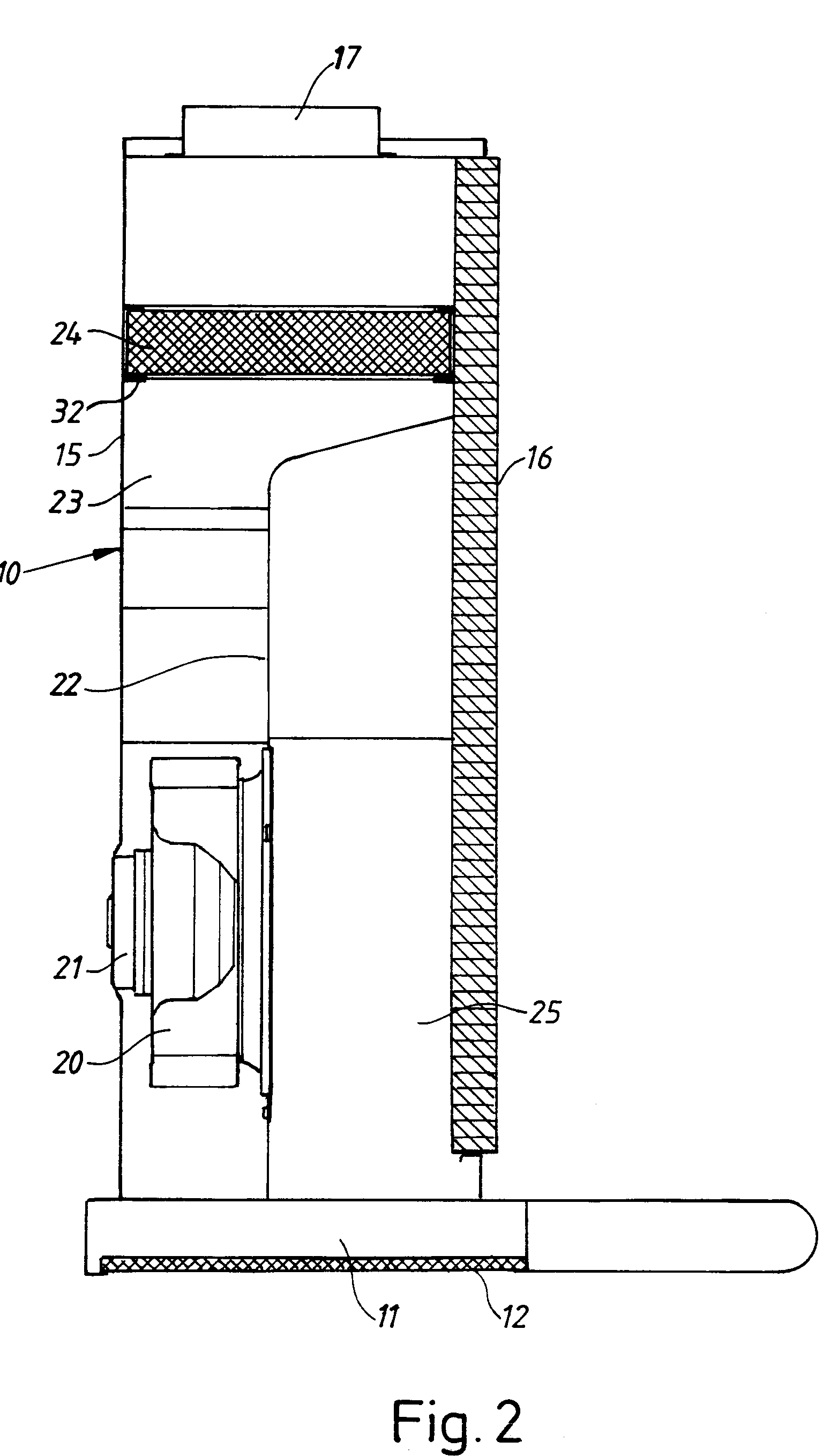
- Figure 2
- is a vertical section of the ventilator.
[0005] The ventilator shown in the drawings comprises a housing 10 which at its lower end
has an inlet 11 provided with a so-called grease filter 12. The housing has vertical
side walls 13, 14, a rear wall 15, and a removable front wall 16 which on its inside
is provided with a sound absorbing material. The housing has an outlet 17 provided
centrally at the upper end thereof.
[0006] A fan 20 having a horizontal axis and powered by an electric motor 21 is provided
at the lower portion of the housing. The interior of the housing is divided by means
of a vertical partition wall 22 into an inlet passage 25 disposed in front of said
partition wall and connected to the inlet 11 of the housing, and an outlet passage
23 disposed behind the wall and connected to the outlet 17. The fan 20 is provided
behind the wall 22 and has an inlet connected to a corresponding opening therein.
The outlet passage 23 is provided at its upper portion with a bracket 32 for an odour
filter 24 which is removable and can be used optionally. The odour filter preferably
contains active carbon and is primarily intended to be used when the air discharged
via the outlet 17 is recirculated, and can be disposed with when the outlet is connected
to an evacuation passage. Between the air filter 24 and the outlet 17 the outlet passage
23 has a narrowing portion 33 which on both sides has chambers 18, 19 provided with
sound absorbing material.
[0007] The space in the housing 10 in front of the partition wall 22 formes an inlet passage
25 extending from the enlet 11 to the fan 20. In this space a baffle wall 26 extends
from one side of the inlet 11 and partially around the fan to the same level as the
top portion thereof. The object of the baffle wall is to screen off the fan noise
from the inlet 11 of the housing. The upper end of the baffle wall is rounded and
surrounds a chamber 27. Air entering the inlet 11 flows upwards through the housing
on the left side of the baffle wall 26 and around the upper end thereof to the fan
20. The inlet passage 25 has a relatively large area which results in a low flow velocity
and consequently a low noice level.
[0008] In order to reduce low frequency noice the ventilator is provided with means for
active silencing of noice comprising a first acoustic sensor 28 provided in the chamber
27 and sensing the fan noise in the vicinity of the fan inlet. The signal from the
sensor 28 is processed in an electronic control unit 29 controlling a loudspeaker
30 provided adjacent the inlet 11 of the housing. The loudspeaker emits a sound which
is phase shifted in such way as to be in reverse phase relative to the sound sensed
by the sensor 28 which is thereby actively silenced. A second acoustic sensor 31 is
provided in the inlet passage 25 adjacent the inlet 11 and is equally connected to
the control unit 29. By means of this second sensor it is monitored that the sound
emitted by the loudspeaker 30 has the correct character and phase shift in order that
the sound silencing operates in the intended manner. If this should not be the case,
the control unit performs a required correction in response to the signal received
from the sensor 31, until the desired result is obtained. Low frequency noice from
the fan 20 can thereby be eliminated to a large extent.
[0009] By means of the ventilator described above it has appeared to be possible to obtain
an essentially reduced noice level without reducing the capacity.
[0010] It is a further essential advantage of the ventilator according to the invention
that it is easily available for cleaning which important from the viewpoint of fire-protection.
By removal of the front wall 16 the inlet passage 25 and the fan 20 are made easily
available. The impeller of the fan is easily removable from the motor 21 whereby the
lower portion of the outlet passage 23 becomes available through the opening in the
wall 22. The top portion of the outlet passage can be made easily available by removal
of the odour filter 24.
1. Kitchen ventilator comprising a housing (10), a motor powered fan (20) having a horizontal
axis arranged in the bottom portion of the housing, an inlet (11), an inlet passage
(25) extending between the inlet and the fan, an outlet (17), and an outlet passage
(23) extending between the fan and the outlet, said passages being separated by a
generally vertical partition wall (22), characterized in that the inlet passage is formed partially by a baffle wall (26) provided between
the inlet (11) and the fan (20) and a removable front wall (16) provided with a sound
absorbing material, said outlet passage (23) having a narrowing portion (33) which
is provided on both sides with sound absorbing material (18, 19).
2. Kitchen ventilator according to claim 1, characterized in that the outlet passage (23) is provided with a bracket (32) for a removable odour
filter (24).
3. Kitchen ventilator according to claim 1 or 2, characterized by means for active silencing comprising an acoustic sensor (28) for sensing the noice
of the fan, a loudspeaker (30) for emitting a sound silencing the fan noice in reverse
phase therewith, and an electronic control unit (29) connected to said sensor and
said loudspeaker and adapted to control the loudspeaker in response to information
received from said sensor.
4. Kitchen ventilator according to claim 3, characterized by a first acoustic sensor (28) for sensing the fan noice in the vicinity of the fan
(20), and a second acoustic sensor (31) for sensing the fan noice at the inlet (11),
both sensors being coannected to the control unit (29) whereby the sound emitted by
the loudspeaker is corrected in response to information received from said second
sensor.