| (19) |
 |
|
(11) |
EP 0 198 657 B1 |
| (12) |
EUROPEAN PATENT SPECIFICATION |
| (45) |
Mention of the grant of the patent: |
|
27.07.1994 Bulletin 1994/30 |
| (22) |
Date of filing: 09.04.1986 |
|
| (51) |
International Patent Classification (IPC)5: G02B 6/38 |
|
| (54) |
Connectors for optical fibres
Verbinder für optische Fasern
Connecteurs pour fibres optiques
|
| (84) |
Designated Contracting States: |
|
CH DE FR GB IT LI NL SE |
| (30) |
Priority: |
11.04.1985 CA 478876
18.09.1985 CA 478876
|
| (43) |
Date of publication of application: |
|
22.10.1986 Bulletin 1986/43 |
| (73) |
Proprietor: Sezerman, Omur M. |
|
Nepean, Ontario, Canada K2H 7T9 (CA) |
|
| (72) |
Inventor: |
|
- Sezerman, Omur M.
Nepean, Ontario, Canada K2H 7T9 (CA)
|
| (74) |
Representative: Spall, Christopher John et al |
|
BARKER, BRETTELL & DUNCAN
138 Hagley Road
Edgbaston
Birmingham B16 9PW
Edgbaston
Birmingham B16 9PW (GB) |
| (56) |
References cited: :
GB-A- 2 012 984
GB-A- 2 062 893
US-A- 4 296 999
|
GB-A- 2 053 784
US-A- 4 087 155
|
|
| |
|
|
- PATENT ABSTRACTS OF JAPAN, vol. 7, no. 30 (P-173)[1175], 5th February 1983; & JP-A-57
181 520
|
|
| |
|
| Note: Within nine months from the publication of the mention of the grant of the European
patent, any person may give notice to the European Patent Office of opposition to
the European patent
granted. Notice of opposition shall be filed in a written reasoned statement. It shall
not be deemed to
have been filed until the opposition fee has been paid. (Art. 99(1) European Patent
Convention).
|
[0001] The present invention relates to connectors used to effect connections between separate
lengths of optical fibres, and more particularly to connectors which are adjustable
to optimize the transmission of light energy through the joint and which do not lose
their adjustment when one or the other fibre is disconnected from and reconnected
to the connector.
Background Of The Invention
[0002] The use of optical fibres for the transmission of data or optical information has
increased dramatically in recent years. The heart of such transmission systems is
an optical fibre of silica glass or other suitable material which has been clad with
an appropriate material to achieve a "light tube" or waveguide along which light energy
can travel in a controlled manner. Optical fibres are extremely small (maybe 100 microns
in diameter) and when they are incorporated into a data transmission system it is
necessary to effect inter-connections between separate lengths of such fibres. The
primary function of an optical connector is to provide a low-loss coupling of light
energy from one fibre to the next and it is necessary to align, in an extremely precise
manner, the cores of the coupled fibres so as to keep the losses at the joint to an
absolute minimum.
[0003] The best coupling possible between two fibres is achieved by polishing the ends of
the fibres to a smooth finish and then directly butting the ends together. Disregarding
any fresnel losses at the glass-air interface such a connection should have losses
in the order of 0.2dB. This type of connection requires high precision equipment and
is best suited for permanent splices. For repeated connections a more rugged connector
is required, but such can lead to increased losses.
[0004] There are six main sources of losses in any fibre to fibre coupling system. The greatest
losses are due to lateral misalignment, when the mating fibres are not aligned along
their central axes. Also, although manufacturers place tight tolerances on the position
of the core within the cladding, any eccentricity of the central core is treated as
a lateral misalignment condition. Angular losses occur when the central axes of the
two fibres are tilted with respect to each other. End separation losses occur when
the ends of the mating fibre are separated. Greater separations result in greater
losses since light emananting from the end of an optical fibre is projected in the
form of a cone. Dirt, surface irregularities and non-perpendicular ends conspire to
keep the ends apart and generate losses. Extrinsic connector (intrinsic fibre) losses
are caused by variations in the optical parameters of the fibre, including its "numerical
aperture" (NA), concentricity of the core, core ellipticity and diameter variations.
Finally, fresnel losses occur whenever light passes from one transparent medium into
another medium of a different index of refraction, since part of the transmitted light
will be lost to a reflected beam. For transmission from glass to air the fresnel losses
can be 0.2dB for each surface. This loss can be eliminated by using index-matching
fluids, or reduced by using anti-reflection coatings.
[0005] In order to minimize losses such as described above the tolerences of butt-joint
connections must be extremely tight. However, any small piece of dirt which enters
the joint can drastically increase the losses of the connection and accordingly the
ends of the fibre must always be protected from ambient conditions.
[0006] The problems associated with connections as described above can be reduced by the
use of "expanded beam" technology through which the optical beam diameter is increased
from the core diameter of 100 microns up to a more manageable size of a few millimeters.
Since the resulting beam is considerably larger than a speck of dirt the losses associated
therewith are reduced. Furthermore since one is dealing, relatively speaking, with
a macro rather than a micro situation all aspects of the connection become simpler,
from manufacture, to maintenance.
[0007] If a fibre is placed at the focal point of a lens then the beam emerging from the
lens is collimated with diameter much larger than that of the fibre core and if each
fibre has an appropriate lens the spot image from one will be formed on the other
at the focal point of its lens. Expanded beam connectors obviously reduce losses due
to lateral misalignment and end separation. However, due to the auto-collimation such
connectors increase the losses due to angular misalignment.
[0008] In principle, if the fibres are positioned at the focal point of the lenses with
the same accuracy as with end-to-end butt joint connections the losses should be the
same with an expanded beam coupler. Several couplers using expanded beam technology
are presently available commercially. One of the easiest lens to use in fibre connectors
is the graded index (GRIN) lens.
[0009] Cylindrical GRIN lenses are functionally identical to conventional spherical lenses
except that they have flat end surfaces. The change in the index of refraction along
its axis generates the unique properties of the GRIN lens and lenses can be tailored
by the manufacturer to generate a wide range of optical parameters. The length of
a lens defines its pitch, or the fraction of a complete wavelength, that is contained
within the lens at a particular wavelength. For the production of a collimated beam
from a point source it is necessary to use a quarter-pitch lens.
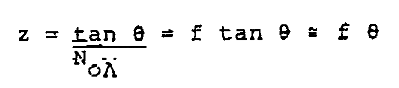
[0010] If one quarter-pitch GRIN lens in a joint is tilted by an angle ϑ relative to the
other lens then the transmitted image will be displaced relative to the receiving
lens axis by an amount given by the equation

where ϑ is the tilt angle; No and A are GRIN lens parameters which determine the
focal length of the lens, since

. For different types of specific GRIN lenses the losses due to a tilt angle of 1
degree can range from about 6dB to well over 10dB. Furthermore, as the fibre core
size decreases the tilt losses will become more severe. In a GRIN lens connector if
there is any tilt variation in the lenses or even in the placement of the fibres then
the transmitted image will not be focussed on the receiving fibre. It therefore is
very desirable to achieve a connector in which the tilt losses are minimized without
demanding extremely high (costly) manufacturing tolerances.
[0011] The principles stated above apply to other imaging lenses, not just to GRIN lenses.
If the image is formed at the focal point of the lens then a tilt through the angle
ϑ will produce a translation of
at the fibre end face. For small angles

.
[0012] U.S. Patent 4,265,511 discloses a multi-piece connector in which two sections, each
carrying a ferrule containing an optical fibre, are threadedly connected together
to bring opposing reference faces into contact with each other. Each ferrule contacts,
and pivots on, a spherical lens. Adjusting means are provided at the opposite ends
of the ferrules for adjusting the optical axis of the fibre carried thereby so that
it is parallel to the optical axis of the housing.
[0013] U.S. Patent 4,290,667 discloses a plurality of different terminations for an optical
fibre, each involving a beam expanding lens. Adjustment is available to ensure that
the fibre end coincides with the lens focus, by way of an adjusting screw.
[0014] Published British Application 2,091,899A discloses a fibre optic rotary joint in
which the fibres are coaxial with the joint. In one embodiment spring-tensioned screws
are used for micro-adjustment of one fibre relative to the other fibre, although such
adjustment will be less than optimum given the tolerances of the rotary bearing arrangement
and the wear that will occur therein during operation of the joint.
Summary of the Invention
[0015] The present invention is defined in the independent claims and is intended to overcome
specifically the tilt problems associated with beam expanding or imaging lens type
connectors or couplers and the extremely high tolerance requirements of placing the
fibre end at the focal point of the lens. The present invention is embodied in a new
connector or coupling device which is economical to manufacture, may be easily hermetically
sealed in use, is effortlessly manipulated during disconnection and reconnection,
and is adjustable to optimize the transmission of light energy therethrough. The coupling
device of the present invention uses the properties of lenses in combination with
novel tilting techniques to achieve a compact structure capable of submicron resolution.
Furthermore, with very little, or even no, adjustment devices embodying the principles
of the present invention could be used as source couplers, attenuators or connectors
to couple light into any size or number of receiving fibre(s).
[0016] Throughout the disclosure and claims it should be understood that the word "optimum"
and its variants is intended to have a broad meaning, such as "most favourable under
defined conditions". The "optimum" signal strength for a coupler might be the maximum
obtainable, whereas for an attenuator it would be a desired signal strength, less
than maximum.
[0017] In one form the present invention utilizes a pair of base plates each having a threaded
boss thereon and an axial bore therethrough. Each bore is adapted to receive in a
predetermined position therein a holder which carries a beam expanding or imaging
lens and an optical fibre associated therewith. The lens holder has a nut thereon
for threaded connection to the boss of the base plate such that the holder can be
disconnected from the base plate and reconnected thereto. A resilient member is sandwiched
between confronting faces of the base plate and threaded screws interconnect the base
plates by passing from one plate through the resilient member to the other plate.
The central void area of the resilient member contains the opposing faces of the lenses
and may be hermetically sealed from the surrounding atmosphere by sealing contact
with the base plates. Once the connector has been assembled a test light can be transmitted
from one fibre through the connection to the other fibre and then to a suitable receiver.
The threaded screws can then be adjusted to alter the angular orientation of one base
plate relative to the other so as to alter the angular orientation of one lens and
its fibre relative to the other. During adjustment the receiver is monitored and the
screws are adjusted in a pattern until the detected output is optimized at which point
the adjusting procedure is stopped. Even if one or both of the fibres is disconnected
from the joint as described above the base plates will hold their adjusted condition
and the fibres can be reconnected to the joint without fear of any increase in losses
after reconnection.
[0018] Broadly speaking, therefore the present invention may be considered as providing
a coupling device for optically coupling a pair of optical fibres in end-to-end relation,
each of the fibres terminating at a beam expanding or imaging lens, comprising: base
means for each of the fibres, each such base means including an axial bore and means
for securing one of the lenses therein; a resilient member positionable between and
against confronting end faces of the base means, the resilient member permitting
passage of light energy thereacross; and axially extending securing and adjusting
means interconnecting the base means with the resilient member trapped therebetween;
whereby the securing and adjusting means are individually axially displaceable to
effect an angular adjustment of one base means relative to the other so as to optimize
the light energy transmissable from one fibre and its lens to the other lens and its
fibre.
Brief Description of the Drawings
[0019] Figure 1 is a side view of the optical fibre coupling device of the present invention.
[0020] Figure 2 is a composite view of the major components of the coupling device of the
present invention.
[0021] Figure 3 is a cross-section of an optical fibre and lens holder receivable in a base
plate of the present invention.
[0022] Figure 4 is a side view of a second embodiment coupling device in accordance with
the present invention.
[0023] Figure 5 is a composite view of the major components of the second embodiment of
the present invention.
[0024] Figures 6A and 6B show simplified cross-sectional views of the connections possible
with the second embodiment.
[0025] Figure 7 shows a tool usable to insert the components of the second embodiment.
[0026] Figure 8 shows a bulkhead connector using the principles of the present invention.
[0027] Figures 9 and 10 show cross-sectional views of two one-end couplers (optical switches)
with the coupler of Fig. 10 using the principles of the present invention.
[0028] Figures 11A, 11B, 11C and 12 show monitoring connectors unable with the present invention.
[0029] Figure 13 shows a beam splitter using the principles of the present invention.
[0030] Figures 14 and 15 show two embodiments of a radially adjustable coupling device using
the principles of the present invention.
[0031] Figure 16 shows an embodiment similar to that of Figure 1 but using a hemispherical
fulcrum about which tilt adjustment is possible.
[0032] Figure 17 shows an embodiment similar to that of Figure 15 but using a spherical
fulcrum member for tilt adjustment.
[0033] Figure 18 shows an embodiment similar to that of Figure 15 but using a spherical
lens instead of a cylindrical lens.
[0034] Figure 19 shows another embodiment similar in some respects to that of Figure 16.
Description of the Preferred Embodiment
[0035] The basic optical fibre coupling device according to the present invention is illustrated
in Figure 1 under reference number 10. The coupling device 10 is used to join a pair
of optical fibre assemblies 12,14 in end-to-end relation so that an optical signal
in the form of light energy can be transmitted from one assembly to the other with
minimum losses at the joint. The optical fibre assemblies 12,14 typically include
the clad optical fibre core 12a,14a a plastic coating 12b,14b surrounding the core
and a protective cable or sheath 12c,14c surrounding the coating. With reference to
Figure 3 it is seen that each clad fibre core 12a,14a terminates at a graded index
lens (GRIN) 72, which with the fibre core end being positioned at the focal point
of the lens, expands and collimates the optical signal for improved transmission to
the receiving GRIN lens. Suitable GRIN lenses for the present invention are available
under the SELFOC (Trademark) designation from the Nippon Sheet Glass Company.
[0036] With reference to Figures 1 and 2 it will be seen that each optical fibre assembly
12,14 is received in a corresponding base plate 16,18 via an appropriate connection
mechanism to be described herein. Each base plate, 16,18 is provided with a central
boss 20,22 projecting outwardly from one face thereof. Each boss carries external
threads 36 and a central bore 38 extends axially through the boss and its base plate
to exit at the flat obverse face thereof. A keyway 40 is machined in the sidewall
of the bore 38 for a purpose to be described.
[0037] Each fibre assembly 12,14 carries at its end a lens holder 24,28 and each lens holder
in turn carries a nut 26,30 which is free to rotate thereon. Furthermore each lens
holder carries a key 42, which is matable with the keyway 40 provided in the axial
bore 38 of each base plate. When it is desired to assemble a fibre assembly 12,14
to its base plate 16,18 it is only necessary to slide the lens holder 24,28 into the
appropriate axial bore 38 with the key 42 engaging the keyway 40 and to then rotate
the nut 26,30 to engage the internal threads thereof with the external threads 36
on the boss 20,22. When the mating threads are fully engaged the lens holder will
be held in a predetermined position within its base plate.
[0038] Returning to Figure 2 it will be seen that one base plate 16 is provided with circumferentially
spaced through holes 44 positioned adjacent the periphery of the base plate. The other
base plate 18 is provided with circumferentially spaced threaded bores 46 positioned
adjacent the periphery of that base plate, the bores 46 being alignable with the holes
44. Threaded screws 34 are provided for threaded engagement with the threaded bores
46 and for a close fit within the holes 44. The screws 34 should have at least 56
threads per inch, preferably at least 80 threads per inch. A greater number of threads
per inch provides higher resolution in the adjustment step. Finally, a resilient washer
member 32 is provided, the washer member having through holes 48 alignable with the
bores 46 and the holes 44 and also having a central void area 50, the configuration
of which is not critical to the invention.
[0039] The components of Figure 2 are assembled together as shown in Figure 1, with the
fibre assemblies 12,14 connected to the base plates 16,18 and with the base plates
16,18 connected together with the obverse faces thereof in confronting relation and
with the resilient washer member 32 sandwiched between the obverse base plate faces.
The screws 34 pass through aligned holes 44 and 48 and are threadedly received in
threaded bores 46 such that when the screws are tightened they sealingly clamp the
washer member 32 between the base plates 16,18. When initially assembling the base
plates and the washer member together it is advantageous to slide the base plates
on to a centering rod which fits closely within the bores 38, to ensure that the axes
of the base plates are initially aligned when the screws 34 are set at their initial
positions.
[0040] The washer member 32 is shown in Figure 2 as being continuous peripherally and as
having flat surfaces which abut the confronting faces of the base plates. Such a member
is particularly useful if it is desirable to hermetically seal the interior of the
coupler, as in an underwater application. In such an application an O-ring (not shown)
could be placed between the end face of the boss 20,22 and the inner face of the nut
26. If hermetic sealing is not required the washer member 32 could be formed as an
annular spring member, such as a Belleville washer, having appropriate holes through
which the screws 34 could pass. Instead of an annular spring, individual springs located
at each screw 34 could bias the base plates apart. Alternatively the annular spring
member (or the washer member 32) could be located within the circumference defined
by the screws so that it would then not be necessary to have the screws pass through
the washer or spring member itself. Usually the washer member 32 would be formed from
a rubber or soft plastic material, although it would be possible to use a soft metal
(e.g. indium) if desired.
[0041] As an alternative to the washer member 32 described above it would be possible to
hermetically seal the interior of the connector with a commercially available O-ring.
One base plate could be provided with an annular groove in its confronting face, in
which the O-ring is receivable, a portion of the O-ring projecting away from the face
of the base plate. The other base plate need not have a mating groove as its face
will be forced into sealing engagement as the screws 34 are drawn tight. In this embodiment
the O-ring preferably lies within the circumference of the screws 34.
[0042] With reference now to Figure 3, the internal structure of a typical fibre assembly
12 will be described, it being understood that Figure 3 is drawn to a much larger
scale than the components themselves.
[0043] The fibre assembly 12 is made up of several components, namely the clad core 12a
which is typically a silica or a doped silica glass of extremely small diameter (e.g.
100 microns), the plastic coating 12b which surrounds the clad core, and the cable
or sheath 12c which may be formed from a resilient flexible plastics material and
serves to protect the clad core and the plastic coating. The outer diameter of the
sheath will be in the order of 4mm.
[0044] At the end of the fibre assembly the sheath is removed or stripped from the plastic
coating over a short length of about 13mm and an optional, yet desirable, inner crimp
sleeve 52 is fitted over and crimped to the exposed coating 12b. An optional, yet
desirable, outer crimp sleeve 54 is fitted over and crimped to the sheath 12c adjacent
the inner end of the inner crimp sleeve 52. At the free end of the assembly a very
short length of the clad core 12a is exposed.
[0045] The assembly 12 having the sleeves 52 and 54 crimped thereon is slid into a fibre
ferrule 56. Ferrule 56 includes three distinct sections, namely an enlarged first
section 58 having an axial bore 60 therein adapted to loosely receive the outer crimp
sleeve 54, a reduced diamater second section 62 having a reduced diameter blind axial
bore 64 therein adapted to receive the inner crimp sleeve 52, and an end section 66
having a small axial bore 68 therein adapted to securely receive the short length
of clad core 12a from the fibre assembly 12. The end section 66 has a bevelled edge
70. The ferrule 56 can be metallic, plastic or ceramic, depending on the application
of the connector, If for example, the connector is to be used in a high temperature
environment a ceramic ferrule would be desirable since it has a coefficient of thermal
expansion very close to that of the glass used for the optical fibre. Also, if crimp
sleeves are not used the fibre ferrule could be smaller than it would be if crimp
sleeves are used.
[0046] After the portions of sheath and coating have been stripped from the fibre assembly
12, the inner and outer crimp sleeves 52,54 are secured to the coating 12b and the
sheath 12c in the locations as described above. The sleeves may be metallic or plastic
as long as they serve to reinforce the fibre assembly at its end. After fitting the
sleeves to the fibre assembly the fibre ferrule is slid onto the end of the fibre
assembly so that the clad core section fits in the bore 68 and the sleeves 52,54 fit
in the stepped bores 64,60 respectively. The ferrule may be secured to the fibre assembly
12 in any known manner, as by crimping or by potting with an epoxy resin. The fit
between each sleeve 52,54 and its bore 64,60 is slightly loose to permit the potting
material to extend therealong.
[0047] After the fibre ferrule 56 is securely attached to the fibre assembly a graded index
lens 72 of enlarged diameter, such as a SELFOC lens, is soldered or glued within the
end of the lens holder 24. If hermeticity is important the lens could be metallized
so that it can be soldered to the lens holder and thus sealed thereto.
[0048] The ferrule/fibre assembly 56/12 is next assembled into the lens holder 24. The lens
holder 24 is generally cylindrical and is of a length equal to that of the lens 72
and the second and end portions of the ferrule 56. The lens holder 24 has an axially
extending bore 74 adapted to securely receive the lens 72 and the second and end portions
of the ferrule. The lens holder 24 also has an enlarged diameter portion 76 adjacent
its inboard end defining annular shoulders 78 and 80. Furthermore, the barrel of the
lens holder has the longitudinally extending key 42 formed thereon, the actual shape
of the key 42 being immaterial as long as it mates with the keyway 40.
[0049] Before the ferrule 56 is assembled to the lens holder 24, the nut 26 is slid onto
the inboard end of the lens holder. The nut 26 includes internal threads 82, an end
face 84 and flats 86 for engagement by a suitable wrench if necessary. With the nut
in place the ferrule assembly is slid into the bore 74 until the end face of the ferrule,
containing the end face of the clad core abuts the end face of the lens 72. The lens
holder is then secured to the ferrule in any conventional manner as by gluing or potting.
An air hole 88 is provided in the wall of the lens holder at the interface between
the lens 72 and the fibre ferrule 56. It permits the escape of air and/or excess glue
or potting compound when the ferrule is assembled to the lens holder. Also, since
the first section of the ferrule has a slightly greater diameter than that of the
adjacent portion of the lens holder the nut 26 will be free to rotate on the lens
holder but will be captured between the shoulder 80 on the lens holder and the first
section of the ferrule.
[0050] When the two fibre assemblies 12,14 have been constructed as described above, they
may then be assembled to the base plates 16,18 as previously described. The key 42
will engage the keyway 40 and, upon full insertion into the axial bore 38, the shoulder
78 on the lens holder 24 will abut against the outer face of the boss 20,22 on the
base plates 16,18. Thus, by the mechanism of abutting faces and mating keys/keyways
the fibre assemblies will always assume the same predetermined position in their respective
base plates each time they are connected thereto.
[0051] When the connector of the present invention is first assembled there will be no guarantee
that (a) the axis of the fibre core 12a,14a is perfectly aligned with that of its
GRIN lens 72, or (b) that the axes of opposing GRIN lensses 72,72 in the joint are
perfectly aligned. Expressed in a different way, there is no guarantee that the image
transmitted from one fibre will not be offset excessively with respect to the receiving
fibre. Any misalignment will result in losses at the joint. The present invention
obviates that shortcoming by permitting adjustment of the relative angle between the
two GRIN lenses and their fibres to achieve the desired optical energy transmission.
Once adjustment has been accomplished the adjusted condition will be maintained even
though the fibre assemblies are disconnected from and reconnected to the joint connector
10, due to the precision positioning of the assemblies as detailed above. Should the
original adjustment be lost or the optical energy transmitted deteriorate for any
reason the joint can be readjusted to again optimize the energy transmission.
[0052] The initial adjustment of the joint requires a completely assembled joint, a test
source of light and a meter-like receiver. The process is very simple and short in
duration: an optical signal from the test source is beamed along one of the fibre
assemblies, through the joint, to the other fibre assembly, and is received at the
receiver. The receiver will provide a relative indication of the signal strength.
The screws 34 are then rotated so as to move, or "tilt" one of the base plates relative
to the other while the received signal is monitored. The screws have very fine threads
and their movements can be accurately controlled. The operator will quickly ascertain
which screws require adjustment and he will then quickly adjust the appropriate screws
to obtain a desired strength of optical signal passing through the joint. Once the
desired signal strength has been obtained, thereby indicating that the image of the
transmitting fibre is falling on the receiving fibre as desired, the adjustment procedure
is terminated. The combination of a very fine pitch on the screws and the resilient
bias provided by the member 32 is sufficient to hold the screws in their adjusted
condition so as to prevent any unwanted rotation thereof. Should readjustment of the
joint be required later it would be merely necessary to repeat the adjustment procedure
outlined above.
[0053] If further adjustment is not contemplated or if the coupler is to be used in a hostile
environment the screws 34 could be secured relative to the base plates as by gluing,
thereby rendering them immobile. Alternatively it would be possible to glue, pot or
solder the joint between the base plates after the adjustment step to render the joint
immobile, albeit not readjustable.
[0054] The coupler of this invention provides a very low loss connector for optical fibres.
This low loss, less than 0.8 dB, is the result of the precise alignment of the image
of the transmitter fibre on the receiver fibre by control of the tilt angle between
the receiver and transmitter lenses. In the case of 2-56 screws used on a radius of
1.35 cm, one rotation of a screw results in a displacement of 435 microns. In practice,
one can control the rotation of the screw by ±2 degrees, resulting in a resolution
of about ±2.5 microns. With a lever arm of 2.7 cm this translates into an actual resolution
or displacement of the optical image by ±0.28 microns. Of course, the actual angular
resolution depends on the type of GRIN lenses used and the configuration of the connector.
[0055] For small tilt angles ϑ the resolution of the coupler is determined by
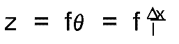
where f is the focal length of the lens, Δx is the resolution of the screws and
l is the lever arm.
Alternative Embodiment
[0056] In the embodiment of Figures 1-3 the optical fibre and its GRIN lens were held in
a lens holder and the other components were attached as indicated. In practice, the
first embodiment can only be used with the appropriate components as described. However,
many manufacturers supply other connectors and these can be adapted to the coupler
of the present invention by using a suitable adapter ferrule. Two such connectors
are the popular SMA type and the AMP* type. It is possible to insert the connector
end of either type into its own adapter so that the end of the connector becomes flush
with the end of the adapter. The connector is then inserted into the base plate and
secured in position with the end of the connector in close proximity to its GRIN lens.
Index matching fluid may be used to minimize optical (fresnel) losses and to provide
a smooth interface between connector and GRIN lens, as by reducing the friction at
the lens/connector interface.
[0057] Figures 4 to 6 illustrate a "universal" coupler which is adapted to accommodate fibre
assemblies which terminate with SMA and AMP-type connectors. Where appropriate the
reference numbers of Figures 4 to 6 use the same basic numbers as Figures 1 to 3,
increased however by 100. Thus, in the alternative embodiment of Figures 4 to 6 the
coupler of the invention carries the reference designation 110.
[0058] The coupler 110 is used to connect together fibre assemblies 112,114 and uses the
same basic principles as the previously described connector. The coupler 110 uses
matching circular base plates 116,118 having bosses 120,122 rising from one face thereof.
In this embodiment the axial through bore 138 of each base plate is of a larger diameter
than in the first embodiment and the bosses are internally threaded, as at 136, rather
than externally threaded. As with the first embodiment a resilient washer member 132
having a void area 150 is placed between confronting faces of the base plates 116,118
and fine-pitch threaded screws 134 connect the base plates together, passing through
the bores 144 in one base plate and the passages 148 in the washer member to be received
in the threaded bores 146 in the other base plate. When assembled together the interior
of the coupler 110 will be hermetically sealed from the surrounding atmosphere. It
is understood that alternative resilient members as described in relation to the first
embodiment could be used with this embodiment as well.
[0059] Figures 5, 6A and 6B show various of the components used in this embodiment. Specifically,
the figures show the fibre assembly 112 terminated by an AMP-type connector 124 with
a captured rotatable nut 126 thereon, and the fibre assembly 114 terminated by an
SMA-type connector 128 with a captured rotatable nut 130 thereon. Since the AMP and
SMA-type connectors are well-known it is not necessary to discuss the construction
thereof in detail, except to say that they have the general appearance as illustrated.
[0060] To effect the necessary connection of the fibre assemblies 112,114 to the coupler
110 it is necessary to provide appropriate adapters and these are illustrated as items
140 and 142. Adapter 140 (Figure 6A) has a major diameter portion 152 having an external
thread 154 matable with the internal thread 136 of the boss 120 and a minor diameter
portion or boss 156 extending from the external face thereof, the portion 156 having
an external thread engageable by the threaded nut 126. The adapter 140 has an internal
bore 160 configured to receive the frustoconical end portion of the AMP-type connector
124.
[0061] The adapter 142 has a major diameter portion 162 externally threaded as at 164 for
engagement with the internal threads 136 of the boss 122, and a minor diameter portion
or boss 166 externally threaded as at 168 for engagement with the nut 130. An axially
extending bore 170 is configured to receive the cylindrical end of the SMA-type connector
128.
[0062] Neither of the connectors 124,128 is provided with a GRIN lens and accordingly it
is necessary to provide, for each base plate, a lens holder 172 having an axial bore
174 sized to receive an appropriate GRIN lens (not shown). The lens holders 172 are
externally threaded as at 176 for threaded engagement with the internal thread 136
of the bosses 120,122. The GRIN lenses used in the lens holders 172 will be similar
to those used in the first embodiment.
[0063] When assembling the coupler 110 one can first of all assemble the two base plates
116,118 together with the resilient washer 132 captured between the confronting faces
of the base plates by using the screws 134, as shown in Figure 4, and as described
for the first embodiment. Preferably a centering rod will be used to initially align
the base plates during assembly thereof. Then, one of the lens holders 172 (with a
GRIN lens secured in bore 174) is threaded into one of the bores 138 by using a tool
78 as shown in Figure 7. The tool 178 includes a handle portion 180 with a pair of
pins 182 projecting from one end thereof. The pins 182 cooperate with through bores
184 provided in the lens holders 172 and the adapters 140,142 so that rotation of
the tool 178 will rotate the lens holder or adapter into or out of the appropriate
bore 138. Bores 184 act as air or resin exhaust holes and permit air or resin to escape
from the interior of the coupler during assembly.
[0064] With the lens holders in place the adapters 140,142 are threaded into the respective
bores 138 using the tool 178 so that the adapter abuts the previously positioned lens
holder 172. An O-ring or sealing washer 186 may be placed against the end face of
the reduced diameter portion of the adapters 140,146 to absorb the force exterted
by the connector ferrule on the lens and then the connector 124,128 is slid into its
appropriate adapter. The nuts 126,130 are tightened on the threads of the adapter
to complete and seal the connection.
[0065] The completed joint is then ready to be tested and adjusted as with the first embodiment.
A test signal is passed through the joint and the screws 134 are adjusted to tilt
one base plate relative to the other until the optimum signal strength, as monitored,
is achieved. The stabilized joint is then ready for use.
[0066] While the joint 110 has been described with regard to one AMP-type and one SMA-type
terminal connection it is clear that any combination of commercial terminal connectors
could be used in this universal joint as long as appropriately configured adapters,
for positioning in the same locations as adapters 140,142, are available.
[0067] By utilizing the present invention and the principle of adjusting the tilt angle
between two GRIN lenses it is possible to overcome, or at least reduce substantially,
the losses caused by axial and angular misalignments between fibres and lenses and
the angular misalignment between two lenses. The same technique of a four-point suspension
allows the tilt angle to be easily adjusted and then rigidly controlled. At the cost
of having to initially monitor the transmission coefficient one can produce a low
loss, low cost, highly repeatable coupler (first embodiment) or a low loss, universal
coupler (second embodiment). The second embodiment permits the use, through appropriate
adapters, of already terminated standard connectors. Different beam expanding or imaging
lenses could be used to improve the resolution of the displacement and to minimize
the size of the coupler at the expense of slightly greater lateral misalignment losses
due to the tolerances of the mechanical dimensions, typical fibre sizes being in the
range of 10 to 400 microns in diameter.
[0068] In practice the present invention can also be used to improve the coupling in devices
which use any form of imaging or expanded beam technology.
[0069] Several additional constructions utilizing the principles of the invention, and several
alternatives within the principles of the invention are described hereinbelow.
1. Bulkhead Connector (Figure 8)
[0070] One half (116,132) of the joint of the present invention may be attached via the
appropriate screws 134 to an adapter 188 which can be threaded into a bulkhead so
as to efficiently couple light from a large aperture source to an optical fibre. In
this case the GRIN lens within the base plate 116 images the light onto the aperture
of the fibre in fibre assembly 112 and the tilt adjust mechanism ensures that the
image of the source is optimally placed on the receiving fibre. Improved coupling
between LED (light emitting diode) sources and a fibre can be realized by using the
principles of the present invention.
[0071] A variety of radiation sources, such as He-Ne lasers, injection laser diodes, LED's,
may be used and, accordingly, a variety of GRIN lenses may be used in the connector
or joint. For example, a universal-type connector was coupled onto a He-Ne laser using
a 0.25-SLS-3mm SELFOC* lens. The insertion losses were found to be 0.3dB and 0.5dB
for 100/140 0.3 NA SI and 50/125 0.2 NA GI fibres, respectively. A 0.25-SLN-2.0 mm
lens was used for a 10µm, 0.11 NA single mode fibre and insertion losses were measured
at 0.8dB.
2. Single Mode Connector
[0072] The transmission of light via single mode fibres requires very close tolerances for
the core alignment and beam alignment. In many cases the single mode fibre core is
only 10 microns in diameter. With the present invention it is possible to place or
locate the focussing area with an accuracy of ±0.1 microns. This area and its tolerance
is well within the 10 micron core diameter of the 1300 nanometer single mode fibre.
Clearly the principles of the present invention provide an excellent way of connecting
single mode fibres, although due to the extra (lens aberration) losses it is expected
that the insertion losses may rise to 1.6dB. The average loss with the single mode
connector using a SLW-1.8 SELFOC* lens was found to be 1dB.
*Trademark
3. Optical Switches (Figures 9, 10)
[0073] It is clear from the calculations on the accuracy and replacement of the optical
fibre image that a series of optical fibres could be placed at the exit aperture of
a joint of the present invention. By controlling the tilt angle using precision transmission
techniques, such as by using piezo-electric materials, one could tilt the outlet aperture
so that it could be switched from one output fibre to another. This is illustrated
in Figure 9 which does not fall within the scope of any of the independent claims
wherein an input fibre 190 is held in a ferrule 192 along with a pair (as illustrated)
of output fibres 194 adjacent a GRIN lens 196 all held in a case 198. The case 198
has a cavity 200 in which a plane mirror 202 is mounted on a piezo-electric x/y bender
204. Control voltages for x and y movement are fed to the bender 204 as at 206 and
208 respectively and the unit is calibrated so that, upon selection of the appropriate
output fibre, voltages of the required strength are fed to the bender 204 such that
the optical signal from the input fibre 190 is reflected (dotted lines) to the selected
output fibre 194.
[0074] Figure 10 illustrates another construction which could be utilized as an optical
switch and which could also be considered as a one-end connector. In Figure 10 a base
plate 16, as described with reference to the first embodiment, carries a lens holder
24 within its bore 36. The lens holder carries a GRIN lens 72 and a fibre ferrule
56 as before. In this instance the screws 34 pass through the base plate 16 and a
resilient washer member 32 and are received in a mirror support 210 which, in turn,
mounts a plane mirror 212 in its inner surface. The fibre ferrule 56 carries a plurality
of optical fibres, one of which is identified as 214 and is axially positioned in
the holder, the others of which are identified as 216,218 and are symmetrically arrayed
about fibre 214. Fibre 214 may be considered as the input fibre and the fibres 216,218
may be considered as the output fibres, it being understood that the construction
is not limited to the illustrated configuration using three fibres.
[0075] By appropriately adjusting selected ones, or pairs, of the screws 34 it is possible
to tilt the mirror 212 relative to the optical axis of the base plate 16 and the fibres
214,216,218 so that an optical signal transmitted by the input fibre 214 and imaged
by the lens on the mirror 212 may be reflected by the mirror 212 to any selected one
of the output fibres 216,218. Desirably, the selection procedure would be mechanised
by having each screw 34 connected to be driven by a servomotor (not shown) and the
servomotors in turn suitably controlled, as by a microcomputer, so that the appropriate
tilt adjustment of the mirror 212 could be effected via appropriate operation of the
servomotors merely through identification of the selected output fibre.
4. Feedback and Alternative Monitoring (Figures 11A, 11B, 11C, 12)
[0076] When discussing the principles of the invention hereinabove, the fine adjustment
of the coupler of the invention was achieved through a procedure wherein a test source
of light energy was transmitted from one fibre, through the coupler to the other fibre
and the output of the other fibre was monitored until the monitored signal was a maximum,
at which point the connector was considered to be in adjustment. That technique is
satisfactory for short fibre lengths but becomes rather awkward if the fibres are
several kilometres long, as might be the case with telephonic data systems.
[0077] An alternative monitoring technique is described herein with reference to Figures
11 A to C and is based on the principle that if the plastic coating is stripped from
the clad fibre core and is replaced by a material having a low attenuation coefficient
and a higher index of refraction than the cladding then the cladding modes (light
energy within the cladding) will be stripped therefrom and will be detectable within
the surrounding material. If the stripped modes are minimized then the maximum energy
can be considered to be passing along the fibre core. By using a suitable detector,
connected to a suitable monitor, it is possible to monitor the stripped cladding modes
of the coupler during adjustment so as to optimize the adjustment.
[0078] Figures 11A and 11B show a detector 220 formed from a suitable plastics material
and carrying therein four detector fibres 222. A central longitudinally extending
groove 224 is provided in the detector 220 with the fibres 222 being symmetrically
arranged thereabout. An outer sheath 226 is provided so that it can be rotated on
the detector body to cover the groove 224. Fibres 222 will be connected to the monitor.
[0079] The detector 220 is shown in Figure 11C as being connected to the one-end connector
or optical switch of Figure 10. In this case the plastic coating is stripped from
the output fibres 216,218 at the end of the ferrule 56 and a translucent resin compound
228, having a higher index of refraction than that of the cladding, is potted around
the stripped areas of the fibres 216,218. The detector is positioned so that all of
the fibres 214,216,218 are located in the groove 224 and the polished ends of the
detector fibres 222 abut the resin 228. The sheath 226 is rotated to cover the groove
to prevent inadvertent decoupling of the detector. The fibres 222 are connected to
a monitor 230 and the test signal is transmitted along the input fibre 214.
[0080] If the mirror 212 is tilted via screws 34 to reflect the signal to, say, the upper
output fibre 218 in Figure 11C the monitor 230 will register a certain amount of light
being received by the fibres 222 due to light escaping from the fibre 218 into the
material 228. More light will escape into the material 228 as the reflected light
focussed by the lens 72 strays from the end of the selected fibre 218. When the screws
34 have been adjusted to the point where the light energy monitored is a minimum that
then is an indication that a maximum of light energy is travelling along the fibre
core and that the connector is in proper adjustment. The detector can then be removed
or it can be glued in position as a permanent part of the structure.
[0081] The detector 220 of Figures 11A and 11B shows four fibres 222 symmetrically located
about the axis of the fibre ferrule. It would also be possible to utilize three symmetrically
located fibres 222. Furthermore, if the resin portion 228 is long enough a single
detector fibre might suffice since the stripped modes lose their directional properties
within a few centimetres due to scattering of the light within the resin 228. Once
the light has scattered and is reasonably evenly dispersed in the resin 228 the scattered
light can be detected by a single fibre. More detector fibres are required when the
stripped modes are more directionally oriented.
[0082] With the just-described detector system adjustment of the connector can be achieved
without having to monitor light energy at the end of the output fibre. Furthermore,
this detector system can be used with any of the previously described embodiments
of the invention. Additionally it lends itself to a fully automatic optical switch
as as is basically shown in Figure 10 since if permanently included with the switch
and tied into the microcomputer it would provide a continuous indication of the accuracy
of the selected tilt adjustment and could therefore be used as a feedback to the microcomputer
which would in turn control the servomotors to adjust the screws appropriately until
the optimum signal was being received by the selected output fibre.
[0083] The just described embodiment could be considered as a 1 x 2 optical switch, with
one input fibre and two output fibres. The number of output fibres is determined by
space limitations and thus the switch could be designated as a l x N switch where
N is the number of output fibres. An N x N switch could be devised using the embodiment
of Figure 1 or that of Figure 4 wherein the number of fibres associated with each
base plate is N. In this embodiment an input signal on a fibre associated with one
base plate could be transmitted across the connector to any selected output fibre
associated with the other base plate, merely by adjusting the screws so that the signal
travels the desired path. Signals could pass in either direction. This embodiment
would be particularly effective with a microcomputer controlled servomotor system
for controlling screw movement and would be facilitated by a feedback system such
as described above.
[0084] Figure 12 shows an alternative detector system in conjunction with a structure such
as was used with the first embodiment type of coupler. In this case lens holder 24
carries lens 72 and a fibre ferrule 278 is adapted for reception in the lens holder.
In the ferrule a bare fibre 12a is held in the barrel 280 by a resin 282 having an
index of refraction greater than that of the fibre's cladding and, preferably, a low
light attenuation coefficient so that it will collect more light. The cable or sheath
12c is glued within an enlarged bore 284 of the ferrule as at 286 and a plurality,
such as four, of radial bores 288 extend through the body of the ferrule to the resin
282. Optical detector fibres, such as 290, having a high numerical aperture to collect
as much light as possible are inserted into the bores 288 to detect the stripped modes.
The fibres 290 are in turn connected to a photodetector or monitor as in the previous
embodiment whereby the amount of light in the resin 282 can be monitored and the coupler
can then be adjusted to ensure that the desired amount of light is being transmitted
to the receiving fibre. If the stripped modes have lost their directional sensitivity
in the region of the bores 288 then only a single detector fibre 290 would be required
as the stripped modes would be scattered reasonably uniformly through the resin 282.
5. Attenuators
[0085] Any of the embodiments heretofore and hereinafter described could be used as signal
attenuators merely by adjusting the relative tilt angles of the input and output fibres
so that the transmitted image is offset with respect to the receiving fibre, until
the desired continuously variable signal strength is achieved. It is not always necessary,
or desirable to have the strength of the transmitted signal as great as is possible.
[0086] The tilt principles of this invention result in a reduction of the back reflection
which goes back to the transmitter fibre and this is important for state-of-the-art
laser diodes which can become unstable if too much light is fed back to the laser
diode cavity.
[0087] The attenuation techniques of the invention can be used with single or multi-mode
fibres. They work especially well in single mode applications since the attenuation
will not be mode dependent. The ability to attenuate eliminates the requirement for
pigtail single mode attenuators as one can adjust the connector housing to achieve
optimum coupling or attenuating as desired.
6. Options
[0088]
(i) If desired it would be possible to introduce secondary elements such as polarizors
or neutral density filters into the connectors of the present invention. For example
such devices could be mounted in threaded carriers similar to the lens holder 172
and threadedly introduced into the connector.
(ii) It would also be possible to use the principles of the present invention in apparatus
such as a beam splitter as shown in Figure 13. In this case the beam splitter 292
is surrounded by four base plates 294, shown only schematically since the type of
base plate used could be of any type, including those of the embodiments of Figures
1-3 or 4-6. Each base plate 294 is intended to mount an appropriate lens holder and
a fibre ferrule in its axial bore 296 and the details of such mounting need not be
discussed here. The mounting chassis 298 for the beam splitter 292 provides an air
gap 300 for each base plate and permits a resilient insert 302 to be positioned at
each corner between the chassis 298 and the confronting face of the adjacent base
plate 294. Fine pitch screws 304 clamp each base plate 294 to the chassis 298, passing
through appropriate through holes (not shown) in the base plate and the resilient
insert, and being received in a threaded bore in the chassis. Adjustment of the screws
304 can be performed as previously described in order to achieve the desired coupling
of the fibres through the beam splitter.
(iii) It should also be mentioned that contrary to the foregoing descriptions it is
not always necessary, or even possible, to have a fibre end butting against the adjacent
lens. Abutment between a lens and a fibre end will occur only if the lens is exactly
one-quarter the focal length of the lens. In practice it may be necessary to space
the fibre end from the lens to ensure than the image passing through the lens is focussed
on the fibre end. Any such space or gap between the fibre end and the lens can be
filled with an index matching fluid or resin having a low attenuation coefficient
to minimize losses.
7. Radial Adjustment (Figures 14 and 15)
[0089] Figures 14 and 15 illustrate the use of the principles of tilt adjustment as applied
to optical switches and couplers wherein the adjustment is performed by radially directed
screws rather than by axially directed screws. Radially adjustable devices could be
longer and cylindrically smaller than axially adjustable devices and could have particular
use where axially adjustable devices could not be used due to size limitations.
[0090] Figure 14 shows a simple base plate and fibre assembly combination as might be used
in a bulkhead connector, one end connector, or an optical switch, analogous to the
embodiments of Figures 8 and 10. In this case the base plate 232 has a small diameter
flange 234 provided with circumferentially spaced apart bores 236. A boss 238 projects
rearwardly from flange 234 and a central bore 240 extends the full length of the base
plate. Four radially directed bores 242 positioned away from the flange 234 pass through
the boss 238 into the bore 240.
[0091] A ferrule 244 is provided to mount a beam expanding or imaging lens 246 and a fibre
248 passes through the ferrule 244 to adjacent the lens 246. A spacer means such as
resilient coating or covering 250 is applied to or slid onto the ferrule and radially
directed threaded bores 252 are provided in the ferrule as shown, the bores passing
through the coating 250.
[0092] To assemble the unit the coated or covered ferrule 244 is slid into the bore 240
until the bores 252 align with the bores 242. Fine pitch screws 254 are passed through
bores 242 and threaded into bores 252. Thereafter the unit is attached to a bulkhead
or a mirror assembly (Figures 8,10) by mounting screws 256.
[0093] After connecting a suitable source and monitor to the unit the radially directed
screws 254 can be rotated to move the end of the ferrule up, down or sideways (or
any combination) so as to obtain the desired light transmission, whether maximum or
otherwise. Since the ferrule 244 is covered with the resilient material the screw
adjustments will cause the ferrule and its lens to tilt relative to the base plate
to achieve the desired results.
[0094] The base plate 232 could be replaced by a lens holder such as was described with
respect to Figures 1-3 which lens holder could then be keyed into a base plate and
secured thereto by a suitable locking nut which leaves the screws 254 exposed for
adjustment. Opposing base plates could be secured together and appropriate lens holders
secured in the respective base plates to achieve a fibre-to-fibre connector having
radial tilt properties. Since axial tilt is no longer required in this construction
it would not be necessary to place a resilient member between the confronting base
plate faces.
[0095] Figure 15 shows the principles of radial adjustment as applied to another coupler
260. In this case one end of the coupler body 262 has radially directed bores 242
and can receive, in the longitudinal bore 240 thereof, a ferrule 244 constructed as
in the embodiment of Figure 14. At the other end the body 262 has an external thread
264 and receives a ferrule 266 in the bore 240. The ferrule 266 is simple, containing
a suitable beam expanding or imaging lens 268 and an optical fibre 270. The ferrule
266 has a circumferential flange 272 which abuts the end of the connector body 262
and a nut 274 is provided to clamp the flange 272 against the end of body 262, thereby
holding the ferrule 266 in a predetermined position.
[0096] With all of the components in place a suitable test signal can be sent along one
of the fibres and monitored on the other side of the connector. Screws 254 are adjusted
to tilt the ferrule 244, its lens and fibre until the monitored signal indicates that
the desired signal strength is being transmitted through the connector. After adjustment
the air gap 255 could be filled with epoxy resin to hold everything in adjustment.
[0097] The embodiments of Figures 14 and 15 show simple structures, analogous to the simplified
embodiment of Figure 1. It is understood, however, that suitable lens holders and
adapters could be used to obtain other radially adjustable units, to fit into small
laser diode or light emitting diode modules without departing from the scope of the
invention.
[0098] While not specifically shown it is clear that the arrangement for the adjusting screws
need not be exactly as shown. For example the threaded holes 252 in the ferrule 244
could be eliminated and the through bores 242 in the housing could be threaded so
that the screws are threadedly received in those bores and the ends of the screws
bear against the outer surface of the ferrule (or the resilient coating). Adjustment
of the ferrule would be accomplished in the same manner as previously described. Also
the bores 242 through the housing (threaded or unthreaded) need not be adjacent the
outer part of the housing (left end as in Fig. 15). They could be closer to the center,
in the vicinity of the inner end of the ferrule as it is mounted in the housing.
[0099] Another modification of this invention, which should be clear from Fig. 15, would
be the utilization of identical right and left hand ferrules with the same mounting
mechanism used at each end. For example the left end ferrule could have a captured
nut similar to nut 274 and the housing could be threaded as at 264. It would be necessary,
of course, to have the adjusting screws positioned in the housing so as not to interfere
with the nut after the ferrule is mounted in the housing. Preferably the ferrule 266
and the ferrule 244 will also include a key (not shown) similar to the key 42 shown
in the embodiment of Figure 1 for engagement with a keyway (not shown) in the housing
264 to ensure proper positioning and alignment of the ferrules in the housing.
[0100] As is readily apparent from the foregoing it is possible to execute the principles
of the present invention in several different embodiments, with the adjustment step
being performed either axially or radially relative to the fibres being optically
coupled.
[0101] Additional embodiments are envisioned as illustrated in Figures 16, 17 and 18 wherein
a resilient member or coating is not required. The embodiment of Figure 16 is similar
to that of Figure 1 while those of Figures 17 and 18 are similar to that of Figure
15.
[0102] Figure 16 illustrates a coupler 300 used to optically couple a pair of optical fibre
assemblies 312, 314, which assemblies are essentially identical to the assemblies
12, 14 discussed previously. In this case the fibre assemblies are attached to base
plates 316, 318 via nuts 326, 330 which are carried by the lens holders 324, 328 respectively
and are threadedly engaged with the threaded bosses 320, 322 respectively.
[0103] As with the embodiment of Figure 1 the base plate 316 is provided with circumferentially
spaced-through bores adjacent the periphery thereof and the base plate 318 is provided
with corresponding threaded bores adjacent the periphery thereof. Securing and adjusting
means in the form of screws 334 pass through the bores in base plate 316 and are threadedly
received in the threaded bores of base plate 318.
[0104] A fulcrum for the tilt adjustment of one base plate relative to the other is provided
by a generally hemispherical protrusion or spacer 332 projecting from the face of
one base plate, such as 318, towards the other base plate, such as 316. The protrusion
332 may be integral with the base plate 318 or it may be a separate component appropriately
positioned as shown.
[0105] As illustrated, a portion of the protrusion is received in a cylindrical recess 336
of a smaller diameter provided in the obverse face of the other base plate. When the
screws 334 are initially tightened the protrusion 332 will seat against the circular
edge of the recess 336 and thus the two base plates will be radially located relative
to each other. The screws can then be adjusted as described for the Figure 1 embodiment
so that one base plate can tilt relative to the other to optimize the light energy
transmissable from one fibre and its lens to the other lens and its fibre.
[0106] With this embodiment it is desirable to have the respective GRIN lenses as close
to each other as possible and thus the lens holder 328 should be able to be located
within the base plate 318 such that its lens is at the outermost surface point of
the protrusion 332. Similarly the lens of the lens holder 324 should be at the innermost
surface of the recess 336.
[0107] It is evident that the tilt mechanism as just described operates as a "ball and socket"
type of joint. Thus it would be obvious that the recess 336, instead of being cylindrical
as shown, could be spherical to match the sphericity of the protrusion 332 and that
the recess and/or the protrusion could be coated with a thin layer of a friction-reducing
material such as polytetrafluorethylane. If the base plates 316 and 318 are moulded
from suitable plastic material it may not be necessary to be concerned with friction
or binding between the protrusion and the mating recess.
[0108] If hermeticity is required it would be possible to provide seals such as O-rings
aroung the mating portions of the protrusion and the recess. Similarly a resilient
washer such as item 32 illustrated in Figure 1 could be used, with the protrusion
332 being positioned within the void area 50. Furthermore if optical fibre assemblies
terminating in commerical connectors of the AMP or SMA types (for example) are to
be used it would be possible to use the universal type of connector as shown in Figures
4 and 5 suitably modified to obtain the benefits of the "ball and socket" tilt mechanism
as described above for Figure 16.
[0109] Figure 17 shows a radial connector 460 in which a first ferrule or lens holder 466
is located in one end of a housing 462 and is secured therein by way of a nut 474
engaging the flange 472 of the ferrule and the threads 464 of the housing. The fibre
assembly 470 terminates at the beam expanding or imaging lens 468. As previously mentioned
the ferrule 466 should have a key (not shown) for engagement with a keyway (not shown)
in the housing to achieve repeatable and positive location within the housing.
[0110] A second ferrule 444 carrying a lens 446 and a fibre assembly 448 is positioned within
the housing 462 from the other end thereof. In this instance a spacer in the form
of an annular spherical member 450 is in tight fitting engagement with the ferrule
444 and also engages the inside surface of the housing. Threaded radial bores 442
pass through the housing and receive the securing and adjusting means in the form
of adjusting screws 454, the ends of which screws can contact the ferrule 444 in a
bearing manner. The screws 454 are individually adjustable to alter the angular orientation
of the ferrule 444 relative to the housing 462 and the other ferrule 466 to optimize
the optical signal passing from one fibre to the other.
[0111] In the embodiment of Figure 18 the components 562, 564, 566, 568, 570, 572 and 574
correspond to the equivalent components of Figure 16. The components at the other
end, however, differ considerably in that a second ferrule 544 is mounted in the housing
562 by a threaded nut 552 which engages a flange 556 on the ferrule. A fibre holder
550 carries the fibre assembly 548 and terminates in a spherical lens 546 which is
frictionally held within the ferrule and is welded to the central optical fibre. Threaded
bores 542 pass through the ferrule 544 and receive threaded screws 554. The screws
554 center the fibre holder 550 and also serve to adjust the relative angle of the
holder with respect to the ferrule 544 and the housing 562. The spherical lens 546
acts as a fulcrum for the tilting holder 550. Thus in this embodiment the optimal
signal can pass from one fibre assembly to the other.
[0112] Figure 19 illustrates another coupler, 600, used to optically couple a pair of optical
fibre assemblies 612,614, which assemblies are essentially identical to the assemblies
12,14 of Figure 1. In this case the fibre assemblies are attached to base plates 616,618
via nuts 626,630 which are carried by lens holders 624,628 respectively and are threadedly
engaged with the threaded bosses 620,622 respectively.
[0113] The embodiment of Figure 19 differs from that of Figure 1 in several respects. First
of all the base plates 616,618 are not identical to each other. Base plate 618 is
a standard base plate, similar to plate 18 or 318, whereas base plate 616 is formed
with a spherical surface 636 which confronts the planar face of base plate 618 and
thus acts as a fulcrum for the tilt adjustment of one base plate relative to the other.
[0114] The tilt adjustment is achieved, as with the other embodiments by securing and adjusting
means in the form of screws 634 which pass through through bores adjacnet the periphery
of base plate 616 and are received in corresponding threaded bores adjacent the periphery
of base plate 618. In this embodiment resilient means such as rubber washer, O-rings,
Belleville washers, et cetera, are placed between the head of screw 634 and the rear
face of base plate 616, the resilient means being depicted by reference number 632.
[0115] Adjustment of this embodiment is carried out in the same manner as with the previous
embodiments of Figures 1 and 16 for example.
[0116] This embodiment has several advantages. For example the end separation losses are
reduced since the lenses are physically very close to each other. Also, adjustment
of the coupler is somewhat easier due to the resilient members being between the screw
head and the base plate. When one screw 634 is tightened or loosened the other side
of the base plate can move due to the resiliency of the members 634 and thus it is
not necessary to loosen or tighten the opposite screw to achieve tilting movement
of the base plates relative to each other.
[0117] As with the other embodiments one could effect several variations with this embodiment
without detracting from the invention. The same principles could be used for a coupler
as shown in Figure 5 or for attenuators or other devices. Also, it would be possible
to provide each base plate with a spherical surface such as 636 to increase the degree
of adjustability available. Furthermore, the base plates 616,618 could have a square
periphery (for example) rather than a circular periphery, depending on the particular
location in which it is to be used. That possibility of course exists for the other
embodiments as well.
[0118] Clearly the present invention provides a unique mechanism for coupling an optical
fibre to another fibre or light source such that the joint can be disconnected and
reconnected without any appreciable losses ensuing. The connector is inexpensive to
manufacture and easy to use and represents a significant advance in the optical fibre
art. While certain aspects of the invention have been described herein the invention
is not limited only to what has been illustrated as there are undoubtedly many applications
for the invention which can occur to a skilled workman without departing from the
principles as described. The protection to be afforded this invention is to be determined
from the scope of the claims appended hereto.
1. A coupling device (10; 110) for optically coupling a pair of optical fibres (12, 14;
112, 114) in end-to-end relation, each of said fibres terminating at a beam expanding
or imaging lens (72), and including base means (16, 18; 116, 118) for each of said
fibres, each such base means including a central bore (38; 138) having an axis and
means for securing one of said lenses therein; characterized by a resilient member
(32; 132) positionable between confronting end faces of said base means, said resilient
member permitting passage of light energy thereacross; and a plurality of securing
and adjusting means (34; 134) extending parallel to said axis and interconnecting
said base means (16, 18; 116, 118) with said resilient member (32; 132) trapped therebetween,
whereby said securing and adjusting means (34; 134) are individually displaceable
to effect an angular adjustment of one base means (16, 18; 116; 118) relative to the
other (18; 16; 118, 116) so as to optimize the light energy transmissible from one
fibre and its lens to the other lens and its fibre.
2. The coupling device (10) of claim 1 characterized in that base means (16, 18) includes
a circular base plate having a cylindrical boss (20, 22) projecting away from said
plate, said central bore (38) extending through said boss and said base plate.
3. The coupling device (10) of claim 2 characterized in that said boss (20, 22) is externally
threaded (36) and includes an axially extending keyway (40) in the inner surface defining
said central bore (38).
4. The coupling device (10) of claim 3 characterized in that each of said lens securing
means comprises a lens holder (24, 28) containing said lens (72), said lens holder
(24, 28) including an axially extending external key (42) matable with said keyway
(40) and a rotatable captured nut (26, 30) engageable with said externally threaded
boss (20, 22) whereby said lens holder (24, 28) is receivable in said central bore
(38) of said base means (12, 14) with said key (42) engaging said keyway (40) and
said nut (26, 30) being engageable with said externally threaded boss (20, 22) to
securely hold said lens holder (24, 28) within said central bore (38).
5. The coupling device (10) of claim 4 wherein said optical fibre (12, 14) includes a
central clad optical core (12a, 14a), a coating material (12b, 14b) surrounding said
clad core, and an outer sheath (12c, 14c) surrounding said coating, characterized
in that the termination of the fibre includes a fibre ferrule member (56) which receives
and holds the fibre therein and is receivable in said lens holder (24, 28) such that
the end of said core (12a, 14a) is positionable adjacent said lens (72) at a point
where an image is formed by said lens (72).
6. The coupling device (10) of claim 5 characterized in that said termination includes
a short length of said clad core (12a, 14a) received in a first bore (68) of an end
section (66) of said ferrule (56), an inner crimp sleeve (52) surrounding a bared
length of said coating (12b, 14b) adjacent said short length of core and received
in an intermediate bore (64) of said ferrule (56), and an outer crimp sleeve (54)
surrounding a length of said sheath (12c, 14c) adjacent said inner sleeve (52) and
received in a second bore (60) of said ferrule (56), said inner and outer crimp sleeves
(52, 54) being fixed within said intermediate and second bores (64, 60) respectively
of said ferrule (56).
7. The coupling device (10) of claim 2 - 6 characterized in that said securing and adjusting
means (34) includes a plurality of threaded screws circumferentially spaced apart
adjacent the outer periphery of each said base plate, each screw passing through a
through bore (44) in one base plate and an aligned through bore (48) in said resilient
member (32), and being receivable in a mating threaded bore (46) in the other base
plate.
8. The coupling device (10) of claim 2 - 6 characterized in that said resilient member
(32) has a central void area (50) hermetically sealed from the ambient surroundings,
said securing and adjusting means (34) including a plurality of threaded screws circumferentially
spaced apart adjacent the outer periphery of each said base plate, each screw passing
through a through bore (44) in one base plate and an aligned through bore (48) in
said resilient member (32), and being receivable in a mating threaded bore (48) in
the other base plate).
9. The coupling device (10) of claim 2 - 6 wherein said resilient member is an annular
spring, said securing and adjusting means (34) including a plurality of threaded screws
circumferentially spaced apart adjacent the outer periphery of each said base plate,
each screw passing through a through bore (44) in one base plate, past said annular
spring, and being receivable in a mating threaded bore (48) in the other base plate.
10. The coupling device (110) of claim 2 wherein each of said fibres (112, 114) is provided
with a terminal connector (124, 128) at the end to be optically connected to the other
fibre, characterized by a lens holder (172) for each base means (116, 118), each lens
holder (172) containing a beam expanding or imaging lens (72); means (176) for securing
the lens holder (172) within the central bore (138) of its base means (116, 118);
and adapter means (140, 142) for each base means, each adapter means being adapted
to matingly receive the terminal connector (124, 128) of the optical fibre (112, 114)
associated therewith and to hold the terminal connector (124, 128) adjacent the lens
held in an adjacent lens holder (172).
11. The coupling device (110) of claim 10 characterized in that said base means (116,
118) includes a circular base plate having a cylindrical boss (120, 122) of a smaller
diameter projecting away from said plate, said central bore (138) extending through
said boss (120, 122) and said base plate.
12. The coupling device (110) of claim 11 characterized in that said central bore (138)
is internally threaded (136) and each of said lens holders (172) and adapter means
(140, 142) is externally threaded for reception in said threaded central bore (138).
13. The coupling device (110) of claim 12 characterized in that said resilient member
(132) includes a central void area (150) hermetically sealed from the ambient surroundings
and refraction index matching fluid is provided in said central bores (138) and said
void area (150), between the lens holders (172) held in the respective central bores
(138) of said base means (116, 118).
14. The coupling device (110) of claim 10, 11 or 12 characterized in that each of said
adapter means (140, 142) includes an outwardly projecting externally threaded portion
(156, 168) and each of said terminal connectors (124,128) includes a rotatable nut
(126, 130) captured thereon whereby with said terminal connector (124, 128) received
in said adapter means (140, 142) said nut (126, 130) may be threadedly engaged with
the threaded portion (156, 168) of the adapter means (140, 142) to secure the adapter
means (140, 142) to the terminal connector (124, 128).
15. The coupling device (110) of claim 13 characterized in that each of said adapter means
(140, 142) includes an outwardly projecting externally threaded portion (156, 168)
and each of said terminal connectors (124, 128) includes a rotatable nut (126, 130)
captured thereon whereby, with a resilient washer member (186) in position against
the end face of said threaded portion (156, 168) and said terminal connector (124,
128) received in said adapter means (140, 142), said nut (126, 130) may be threadedly
engaged with the threaded portion (156, 168) of the adapter means (140, 142) to sealingly
secure the adapter means (140, 142) to the terminal connector (124, 128).
16. The coupling device (110) of claim 11, 12 or 13 characterized in that said securing
and adjusting means (134) includes a plurality of threaded screws circumferentially
spaced apart adjacent the outer periphery of each said base plate, each screw passing
through a through bore (144) in one base plate and an aligned through bore (148) in
said resilient member (132), and being receivable in a mating threaded bare (146)
in the other base plate.
17. The coupling device (10) of claim 11, 12 or 13 characterized in that said resilient
member is an annular spring, said securing and adjusting means (134) including a plurality
of threaded screws circumferentially spaced apart adjacent the outer periphery of
each said base plate, each screw passing through a through bore (144) in one base
plate, past said annular spring, and being receivable in a mating threaded bore (146)
in the other base plate.
18. The coupling device (10; 110) of claim 2 - 6, 11 or 12 characterized in that said
resilient member is a resilient annular O-ring captured between said confronting end
faces to define a hermetically sealed void area across which said light energy can
pass, said securing and adjusting means (34; 134) including a plurality of threaded
screws circumferentially spaced apart adjacent the outer periphery of each said base
plate, each screw passing through a through bore (44; 144) in one base plate, past
said O-ring, and being receivable in a mating threaded bore (46; 146) in the other
base plate.
19. The coupling device (10; 110) of claim 1, 2, 3, 10, 11 or 12 characterized in that
said lens (72) is a graded index lens.
20. The coupling device (10; 110) of claim 1, 2, 3, 10, 11 or 12 characterized in that
said resilient member (32; 132) is formed from materials selected from the group including
rubbers, soft plastics and soft metals.
21. The coupling device (10; 110) of claim 2 - 6, 11 or 12 characterized in that said
resilient member comprises a plurality of individual spring means, said securing and
adjusting means (34; 134) including a plurality of threaded screws circumferentially
spaced apart adjacent the outer periphery of each said base plate, each screw passing
through a through bore (44; 144) in one base plate and a through bore in a corresponding
one of said spring members, and being receivable in a mating threaded bore (46; 146)
in the other base plate.
22. A coupling device (188) for optically coupling an optical fibre (112) to a light energy
source surrounded at least in part by a bulkhead through which said source can transmit
light energy, said optical fibre (112) terminating at a beam expanding or imaging
lens (72), and including base plate means (116) for said fibre (112), said base plate
means including a central bore extending therethrough along an axis and means for
securing said lens therein; characterized by a resilient member (132) positionable
between confronting faces of said base plate means (116) and said bulkhead, said resilient
member (132) permitting passage of light energy thereacross; and a plurality of securing
and adjusting means (134) extending parallel to said axis and interconnecting said
base plate means (116) with said bulkhead with said resilient member (132) trapped
therebetween; whereby said securing and adjusting means are individually displaceable
to effect an angular adjustment of said base plate means (116) relative to the bulkhead
so as to optimize the light energy transmissible from said source to said lens (72)
and said optical fibre (112).
23. An optical coupling device comprising an input optical fibre (214) and at least two
output optical fibres (216, 218) positioned adjacent and parallel to said input fibre
(214); base means (16); means (56) fixing said input and output fibres (214, 216,
218) within said base means (16); means (24) holding a beam expanding or imaging lens
(72) in said base means (16) adjacent the ends of said fibres (214, 216, 218); a mirror
support (210) supporting a mirror (212); a resilient member (32) positionable between
confronting faces of said base means (16) and said mirror support (210) respectively;
and a plurality of securing and adjusting means (34) interconnecting said base means
(16) and said mirror support (210) with said resilient member (32) trapped therebetween;
whereby said securing and adjusting means (34) are individually displaceable to effect
an angular adjustment of said mirror (212) relative to said base means (16) such that
an optical signal transmitted along said input fibre (214) through said lens (72)
is reflected by said mirror (212) to be received by a selected one of said output
fibres (216, 218).
24. The coupling device of claim 23 characterized in that each of said securing and adjusting
means (32) is connected to a servomotor controlled by a control means whereby automatic
adjustment of said mirror (212) to reflect said signal to the selected one of said
output fibres (216, 218) is possible.
25. The coupling device of claim 24 characterized in that said control means includes
a microcomputer and feedback means connected to said microcomputer to ensure repeatability
of the positioning of said mirror (212) in response to an adjustment command.
26. The coupling device of claim 25 characterized in that said feedback means includes:
a material (228) surrounding said output fibres (216, 218) having a higher index of
refraction than the cladding thereof, said material (228) serving to capture light
escaping from said cladding; a holder (220) for holding the ends of at least three
symmetrically arranged fibres (222) in abutment with said material (228); and monitoring
moans (230) connected to said symmetrically arranged fibres (222) to monitor the amount
of light energy in said material (228) and to provide a signal to said microcomputer;
whereby said mirror (212) may be adjusted to ensure that a desired amount of light
energy is transmitted to the selected output fibre (216, 218), the amount of light
energy in said material (228) providing an indication of the amount of light energy
transmitted along said output fibre (216, 218).
27. An optical coupling device according to claim 1 comprising a plurality of first parallel,
symmetrically arranged optical fibres (12) and a corresponding plurality of second
parallel, symmetrically arranged optical fibres (14); first means fixing said first
plurality of fibres (12) within a first one of said base means; second means fixing
said second plurality of fibres (14) within a second one of said base means; first
means holding a first beam expanding lens in said first base means adjacent the ends
of said first fibres; and second means holding a second beam expanding lens in said
second base means adjacent the ends of said second fibres; whereby an optical signal
transmitted along a fibre associated with one of said base means can be directed by
adjusting said securing and adjusting means to be received by a selected one of the
fibres associated with the other of said base means.
28. The coupling device of claim 27 characterized in that each of said securing and adjusting
means (34) is connected to a servomotor controlled by a control means whereby automatic
adjustment of said base means relative to each other is possible.
29. The coupling device of claim 27 characterized in that said control means includes
a microcomputer and feedback means connected to said microcomputer to ensure repeatability
of the automatic adjustment of said base means.
30. The coupling device of claim 28 characterized in that said feedback means includes,
for each base means: a material (228) surrounding the fibres associated with the base
means and having a higher index of refraction than the cladding of said fibres, said
material (228) serving to capture light energy escaping from the cladding of any fibre;
a holder (220) for holding the ends of at least three symmetrically arranged fibres
(222) in abutment with said material; and monitoring means (230) connected to said
symmetrically arranged fibres (222) to monitor the amount of light energy in said
material (228) and to provide a signal to said microcomputer; whereby said base means
may be adjusted in response to said signal to ensure that a desired amount of light
energy is transmitted from the one fibre to the selected other fibre, the amount of
light energy in said material (228) providing an indication of the amount of light
energy transmitted along the selected other fibre.
31. A system for monitoring the transmitted light energy in a light receiving optical
fibre (12, 112) included in a coupling device as defined in claim 1, 10 or 22 comprising
a transparent material (228) surrounding a portion of the cladding of said fibre,
said material (228) having a higher index of refraction than said cladding and serving
to capture light escaping from said cladding; a holder (220) for holding the ends
of at least three symmetrically arranged fibres (222) in abutment with said material
(228); and monitoring means (230) connected to said symmetrically arranged fibres
(222) to monitor the amount of light energy in said material (228), which amount provides
an indication of the amount of light energy transmitted along said receiving fibre
(12, 112).
32. A system for monitoring the transmitted light energy in a light receiving optical
fibre (12) included in a coupling device as defined in claim 5 comprising a transparent
material (282) surrounding a portion of he cladding of said fibre (12) within said
fibre ferrule (278), said material (282) having a higher index of refraction than
said cladding and serving to capture light escaping from said cladding; at least one
bore (288) extending radially through said ferrule (278) and terminating at said material
(282); a monitoring fibre (290) held in said bore (288) with its end in contact with
said material (282); and monitoring means connected to said monitoring fibre to monitor
the amount of light energy in said material (282), which amount provides an indication
of the amount of light energy transmitted along said receiving fibre (12).
33. A method of optimizing the light energy transmissible from one optical fibre (12,
112; 14, 114) to another optical fibre (14, 114; 12, 112) within a coupling device
(10; 110) in accordance with claim 1 comprising holding said fibres generally in position
for energy transmission therebetween, transmitting a test optical signal along said
one fibre; monitoring the other fibre to determine the strength of the test signal
received thereby; and adjusting said securing and adjusting means (34; 134) to alter
the mutual angular orientation of the confronting faces of said housing means (16,
18; 116, 118) until the received signal is at the desired strength, thereby indicating
that no further adjustment is required.
34. A method of optimizing the light energy transmissible from one optical fibre (214)
to another optical fibre (216, 218) within a coupling device in accordance with claim
23 comprising holding said fibres generally in position for energy transmission therebetween,
transmitting an optical signal along said one fibre (214) for reflection by said mirror
(212) towards the other fibre (216, 218); monitoring the other fibre (216, 218) to
determine the strength of the optical signal received thereby; and adjusting said
securing and adjusting means (34) to alter the relative angular position of said first
and second housing means (16, 210) until the received signal is at the desired strength,
thereby indicating that no further adjustment is required.
35. The method of claim 33 or 34 wherein said other fibre (216, 218) has a transparent
material (228) surrounding a portion of the cladding thereof, said material (228)
having a higher index of refraction than said cladding and serving to capture light
escaping from said cladding, said monitoring step including the steps of securing
at least one monitoring fibre (222) so that an end thereof is in contact with said
material (228) and connecting the other end of said monitoring fibre to a monitor
(230).
36. A coupling device (260) for optically coupling a pair of optical fibres (248, 270)
in end-to-end relation, each of said fibres terminating adjacent a beam expanding
lens (246, 268) characterized by: elongated cylindrical housing means (262) having
an externally threaded portion (264) at one end and a plurality of circumferentially
spaced apart radially directed through bores (242) at the other end; first ferrule
means (266) containing one (270) of said fibres and an associated lens (268) and carrying
nut means (274) engageable with said threaded portion (264) to secure said first ferrule
means (266) within said housing means (262) at a predetermined position therein; second
ferrule means (244) containing the other (248) of the said fibres and an associated
lens (246), said second ferrule means (244) having a resilient covering (250) thereon
and having a plurality of circumferentially spaced apart threaded bores (252) at the
end opposite the lens (246) carried thereby, each of said threaded bores (252) being
alignable with a corresponding one of said through bores (242) when said second ferrule
means (244) is positioned within said housing means (262); and radially extending
securing and adjusting means (254) extending through said through bores (242) for
engagement with said threaded bores (252); whereby said securing and adjusting means
(254) are individually rotatably displaceable to effect an angular adjustment of said
second ferrule means (244) relative to said housing (262) and said first ferrule means
(266) so as to optimize the light energy transmittable from one fibre and its lens
to the other lens and its fibre.
37. A coupling device for optically connecting an optical fibre (248) to a light energy
source surrounded at least in part by a bulkhead through which said source can transmit
light energy, characterized by housing means (232) securable to said bulkhead and
including a cylindrical portion (238) extending away from said bulkhead generally
in alignment with the path of said light energy, said cylindrical portion (238) including
a plurality of circumferentially spaced apart radially directed through bores (242)
adjacent the end opposite said bulkhead; ferrule means (244) containing said fibre
(248) and an associated beam expanding lens (246) adjacent the end of said fibre (248),
said ferrule means (244) having a surrounding resilient covering (250) thereon and
having a plurality of circumferentially spaced apart threaded bores (252) at the end
opposite said lens (246), each of said threaded bores (252) being alignable with a
corresponding one of said through bores (242) when said ferrule means (244) is positioned
in said cylindrical portion (238); and radially extending securing and adjusting means
(254) extending through said through bores (242) for engagement with said threaded
bores (252); whereby said securing and adjusting means (254) are individually displaceable
to effect an angular adjustment of said ferrule means (244) relative to said housing
means (232) so as to optimize the light energy transmissable from said source to said
lens (246) and optical fibre (248).
38. A method of optimizing the light energy transmissible to an optical fibre (248) within
a coupling device in accordance with claim 36 comprising holding said fibre generally
in position for energy transmission thereto, transmitting a test optical signal beam
into said optical fibre (248) via the beam expanding lens member; monitoring said
fibre (248) to determine the strength of the test signal received thereby; and adjusting
said securing and adjusting means (254) to alter the axial inclination of said holding
means (244) relative to said housing means (232) and the input beam until the received
signal is at the desired strength, thereby indicating that no further adjustment is
required.
39. The method of claim 33, 34 or 38 characterized in that the desired strength of said
received signal is less than the maximum strength of the received signal obtainable
within said coupling device whereby said coupling device is usable as an optical signal
attenuator.
40. An optical beam splitter characterized by a beam splitter support (292) of rectangular
cross-section and having a diagonally disposed beam splitter mirror mounted therein;
a support member (298) on each of the four sides of said beam splitter support, each
support member permitting optical access through an opening (300) thereof to said
mirror; a resilient member (302) on each support member; a base plate (294) on each
resilient member (302); securing and adjusting means (304) extending through each
base plate (294) and its associated resilient member (302) for reception in its associated
support member (298); and boss means on each base plate (294) for mounting, adjacent
said access opening (300), an optical fibre ferrule holding a fibre end adjacent a
beam expanding or imaging lens; whereby said securing and adjusting means (304) are
individually adjustable to alter the angular position of each base plate (294) relative
to said beam splitter support so as to obtain the desired signal strength at each
receiver fibre of an optical signal entering said beam splitter from a transmitter
fibre.
41. A coupling device for optically coupling a pair of optical fibres (448, 470) in end-to-end
relation, each of said fibres terminating adjacent a beam expending lens (446, 468),
including: elongated cylindrical housing means (462); first ferrule means (466) containing
one (470) of said fibres and an associated lens (468) and having means (474) engageable
with said housing means (462) to secure said first ferrule means (466) within said
housing means at a predetermined position therein; second ferrule means (444) containing
the other (448) of said fibres and an associated lens (446), said second ferrule means
(444) having an annular spacer means with a spherical surface portion thereon and
being positionable within said housing means (462) with the lens (446) thereof adjacent
the lens (468) of said first ferrule means (466) and said spacer means in engagement
with an interior surface of said housing means (462); and radially extending securing
and adjusting means (454) extending through said housing means (462) for engagement
with said second ferrule means (444) adjacent one end thereof; whereby said securing
and adjusting means (454) are individually displaceable to effect angular adjustment
of said second ferrule means (454) relative to said housing means (462) and said first
ferrule means (468) so as to optimize the light energy transmissible from one fibre
and its lens to the other lens and its fibre.
42. The device of claim 41 wherein said housing means (462) includes a plurality of circumferentially
spaced apart threaded bores (442) therethrough and each of said securing and adjusting
means (454) is a threaded screw receivable in a corresponding one of said bores (442)
for bearing engagement with said second ferrule means (444).
43. The device of claim 41 or 42 characterized in that said housing means (462) has an
externally threaded portion (464) at each end and each of said ferrule means carries
a nut (474) for threaded engagement with a corresponding one of the threaded portions
on the housing means.
44. The device of claim 41, 42 or 43 characterized in that said spacer means is a spherical
member (450) through which said second ferrule means (444) passes, said spherical
member (450) being receivable within said housing means (462) and serving as a fulcrum
for said second ferrule means (444).
45. A coupling device (300; 600) for optically coupling a pair of optical fibres (312,
314; 612, 614) in end-to-end relation, each of said fibres terminating at a beam expanding
or imaging lens, including base means (316, 318; 616,618) for each of said fibres,
each such base means including a central bore extending therethrough along an axis
and means for securing one of said lenses therein; spacer means between confronting
faces of said base means, said spacer means permitting passage of light therethrough
and permitting and tilting of one base means (316, 318; 616, 618) relative to the
other (318, 316; 618, 616); and securing and adjusting means (334; 634) extending
parallel to said axis and interconnecting said base means (316, 318; 616, 618) with
said spacer means therebetween; whereby said securing and adjusting means (334; 634)
are individually displaceable to effect an angular adjustment of one base means (316,
318; 616, 618) relative to the other (318, 316; 618, 616) so as to optimize the light
energy transmissible from one fibre and its lens to the other lens and its fibre,
characterized in that said spacer means comprises an hemispherical protrusion (332)
projecting from the confronting face of one base means (318), an outer portion of
said protrusion being seatingly receivable in a recess (336) provided in the confronting
face of the other base means (316).
46. The device (300) of claim 45 characterized in that said recess (336) is cylindrical
with a diameter smaller than the diameter of said protrusion.
47. The device (300) of claim 45 characterized in that said recess (336) is spherical
and matches the sphericity of said protrusion.
48. The device (300) of claim 46 or 47 including sealing means positioned between said
protrusion (332) and said recess (336).
49. The device (300) of claim 45 or 46 characterized in that said securing and adjusting
means (334) includes a plurality of threaded screws circumferentially spaced apart
adjacent the outer periphery of said device, each screw passing through a through
bore in one base means (316) and being receivable in a mating threaded bore in the
other base means (318).
50. The device (600) of claim 45 characterized in that the confronting face of at least
one of said base means (616) is formed as a generally spherical surface (636), said
surface constituting said spacer means.
51. The device (600) of claim 50 characterized in that said securing and adjusting means
(634) includes a plurality of threaded screws spaced apart adjacent the outer periphery
of said device, each screw passing through a through bore in one base means (616)
and being receivable in a mating threaded bore in the other base means (618).
52. The device (600) of claim 51 characterized by a resilient member (632) captured between
the head of each screw and the adjacent surface of said one base means (616).
53. A method of optimizing the light energy transmissible from a light source to an optical
fibre (248) within a coupling device (260) in accordance with claim 39 comprising
holding said fibre generally in position for energy transmission thereto, transmitting
light energy from said source for reception by said optical fibre (248); monitoring
said fibre (248) to determine the strength of the transmitted energy received thereby;
and adjusting said securing and adjusting means (254) to alter the angular position
of said ferrule means (244) relative to said housing means (262) until the received
energy is at the desired strength, thereby indicating that no further adjustment is
necessary.
54. The method of claim 53 characterized in that the desired strength of the received
energy is less than the maximum strength of the received energy obtainable within
the device whereby the device is usable as an optical signal attenuator.
55. The method of claim 53 or 54 characterized in that said light source includes a second
optical fibre (270) terminating in a beam expanding lens (268) and held in said housing
means (262) in a predetermined position.
1. Verbinder (10;110) zum optischen Verbinden eines Paars optischer Fasern (12,14; 112,114)
in einer End-zu-End-Beziehung, wobei jede der Fasern an einer strahl-ausweitenden
oder abbildenden Linse (72) endet, und mit Basisteilen (16,18;116,118) für jede der
Fasern, wobei jedes derartige Basisteil eine Mittenbohrung (38;138) mit einer Achse
und eine Einrichtung zum Sichern einer der Linsen aufweist, gekennzeichnet durch einen elastischen Teil (32;132), der zwischen einander gegenüberliegenden Endflächen
der Grundteile positonierbar ist, wobei der elastische Teil einen Durchgang von Lichtenergie
zuläßt, und durch eine Anzahl Sicherungs- und Einstellmittel (34;134), welche parallel
zu der Achse verlaufen und die Basisteile mit dem dazwischen aufgenommenen, elastischen
Teil (32;132) verbinden, wobei die Sicherungs- und Einstelleinrichtungen (34;134)
individuell verschiebbar sind, um eine Winkeleinstellung eines Basisteils (16,18;
116,118) relativ zu dem anderen (18;16), 118, 116) zu bewirken, um so die Lichtenergie
zu optimieren, die aus einer Faser und deren Linse an die andere Linse und deren Faser
übertragbar ist.
2. Verbinder (10) nach Anspruch 1, dadurch gekennzeichnet, daß das Basisteil(16,18) eine kreisförmige Grundplatte mit einem zylindrischen Ansatz
(20,22) aufweist, der weg von der Platte vorsteht, wobei die Mittenbohrung (28) durch
den Ansatz und die Grundplatte hindurchgeht.
3. Verbinder (10) nach Anspruch 2, dadurch gekennzeichnet, daß der Ansatz (20,22) mit einem Außengewinde (36) versehen ist und eine axial verlaufende
Keilnut (40) in der Innenfläche aufweist, welche die Mittenbohrung (38) festlegt.
4. Verbinder (10) nach Anspruch 3, dadurch gekennzeichnet, daß jede der Linsensicherungseinrichtungen einen Linsenhalter (24,28) aufweist,
der die Linse (72) hält, der Linsenhalter (24,28) einen axial verlaufenden äußeren
Keil (42), der in die Keilnut (40) einführbar ist, und eine drehbare Fangmutter (26,30)
aufweist, welche mit dem Außengewinde des Ansatzes (20,22) in Eingriff bringbar ist,
wobei der Linsenhalter (24,28) in der Mittenbohrung (38) der Basisteile (12,14) aufgenommen
ist, wobei der Keil (42) mit der Keilnut (40) in Eingriff steht und die Mutter (26,30)
auf das Außengewinde des Ansatzes (20,22) aufgebracht ist, um dadurch den Linsenhalter
(24,28) in der Mittenbohrung (38) sicher zu halten.
5. Verbinder (10) nach Anspruch 4, bei welchem die optische Faser (12,14) einen zentralen
beschichten optischen Kern (12a, 14a), ein Überzugsmaterial (12b, 14b), das den beschichteten
Kern umgibt, und eine äußere Hülle (12c,14c) aufweist, die den Überzug umgibt, dadurch gekennzeichnet, daß das Ende der Faser einen Faserklemmteil (56) aufweist, welcher in sich die Faser
aufnimmt und hält, und in dem Linsenhalter (24,28) so aufgenommen ist, daß das Ende
des Kerns (12a, 14a) angrenzend an die Linse (72) an einer Stelle positionierbar ist,
an welcher ein Bild durch die Linse (72) erzeugt wird.
6. Verbinder (10) nach Anspruch 5, dadurch gekennzeichnet, daß das Ende eine kurze Länge des beschichteten Kerns (12a, 14a), welcher in einer
ersten Bohrung (68) eines Endabschnitts (66) des Klemmteils (56) aufgenommen ist,
eine Crimphülse (52), welche eine freigelegte Länge des Überzugs (12b, 14b) angrenzend
an die kurze Länge des Kerns umgibt und in einer Zwischenbohrung (64) des Klemmteils
(56) aufgenommen ist, und eine äußere Crimphülse (54) aufweist, welche eine Länge
der äußeren Hülle (12c, 14c) angrenzend an die inner Crimphülse (52) umgibt und in
einer zweiten Bohrung (60) des Klemmteils (56) aufgenommen ist, wobei die inneren
und äußeren Crimphülsen (52,54) in den Zwischen- und zweiten Bohrungen (64, 60) des
Klemmteils (56) befestigt sind.
7. Verbinder (10) nach Anspruch 2 bis 6, dadurch gekennzeichnet, daß die Sicherungs- und Einstelleinrichtung (34) eine Anzahl mit Außengewinde versehenen
Schrauben aufweist, die angrenzend an den Außenumfang jeder Grundplatte entlang des
Umfangs in Abständen voneinander angeordnet sind, wobei jede Schraube durch eine Durchgangsbohrung
(44) in einer Grundplatte, durch eine ausgerichtete Durchgangsbohrung (48) in dem
elastischen Teil (32) hindurchgeht und in einer dazu passenden Gewindebohrung in der
anderen Grundplatte aufgenommen ist.
8. Verbinder (10) nach Anspruch 2 bis 6, dadurch gekennzeichnet, daß der elastische Teil (32) einen zentralen offenen Bereich (50) aufweist, der
luftdicht gegenüber den Umgebungsteilen abgedichtet ist, wobei die Sicherungs- und
Einstelleinrichtung (24) eine Anzahl Gewindeschrauben aufweist, die angrenzend an
den Außenumfang jeder der Grundplatten entlang des Umfangs in Abständen voneinander
angeordnet sind, wobei jede Schraube durch eine Durchgangsbohrung (44) in einer Grundplatte
und durch eine ausgerichtete Durchgangsbohrung (48) in dem elastischen Teil (32) hindurchgeht
und in einer dazu passenden Gewindebohrung (48) in der anderen Grundplatte aufgenommen
ist.
9. Verbinder (10) nach Anspruch 2 bis 6, bei welchem der elastische Teil eine ringförmige
Feder ist und die Sicherungs- und Einstelleinrichtung (34) eine Anzahl Gewindeschrauben
aufweist, die angrenzend an den Außenumfang jeder Grundplatte entlang des Umfangs
in Abständen voneinander angeordnet sind, wobei jede Schraube durch eine Durchgangsbohrung
(44) in einer Grundplatte vorbei an der ringförmigen Feder hinduchgeht und in eine
dazu passende Gewindebohrung (48) in der anderen Grundplatte aufgenommen ist.
10. Verbinder (110) nach Anspruch 2, dadurch gekennzeichnet, daß jede der Fasern (112, 114) mit einem Endverbinder (124, 128) an dem Ende versehen
ist, das mit der anderen Faser optisch zu verbinden ist, gekennzeichnet durch einen Linsenhalter (172) für jedes Basisteil (116, 118), wobei jeder Linsenhalter
(172) eine strahl-ausweitende oder abbildende Linse (72) enthält; eine Einrichtung
(176) zum Sichern des Linsenhalters (172) in der Mittenbohrung (138) des jeweiligen
Basisteils (116, 118) und ein Adapterteil (140, 142) für jedes Basisteil, wobei jedes
Adapterteil den Endverbinder (124, 128) der zugeordneten optischen Faser (112, 114)
passend aufnehmen und den Endverbinder (124, 128) angrenzend an die in einem angrenzenden
Linsenhalter (172) gehalterte Linse halten kann.
11. Verbinder (110) nach Anspruch 10, dadurch gekennzeichnet, daß der Basisteil (116, 118) eine kreisförmige Grundplatte mit einem zylindrischen
Ansatz (120, 122) mit einem kleineren Durchmesser aufweist, welcher weg von der Platte
vorsteht, wobei die Mittenbohrung (138) durch den Ansatz (120, 122) und die Grundplatte
verläuft.
12. Verbinder (110) nach Anspruch 11, dadurch gekennzeichnet, daß die Mittenbohrung (138) ein Innengewinde (136) aufweist, und jeder der Linsenhalter
(172) und der Adapter (140, 142) zur Aufnahme in der mit Gewinde versehenen Mittenbohrung
(138) ein Außengewinde aufweisen.
13. Verbinder (110) nach Anspruch 12, dadurch gekennzeichnet, daß der elastische Teil (132) einen zentralen freien Bereich (150) aufweist, der
luftdicht von den Umgebungsteilen abgeschlossen ist, und ein Fluid mit passendem Brechungsindex
in der Mittenbohrung (138) und dem freien Bereich (150) zwischen den Linsenhaltern
(172) vorgesehen ist, die in den entsprechenden Mittenbohrungen (138) der Basisteile
(116, 118) gehalten sind.
14. Verbinder (110) nach Anspruch 10, 11 oder 12, dadurch gekennzeichnet, daß jeder der Adappter (140, 142) einen nach außen vorstehenden Teil (156, 168)
mit Außengewinde aufweist, und jeder der Endverbinder (124, 128) eine drehbare, gefangene
Mutter (126, 130) aufweist, wobei zusammen mit dem in dem Adapter (140, 142) aufgenommenden
Endverbinder (124,128) die Mutter (126, 130) auf den mit Außengewinde versehenen Teil
(156, 168) des Adapters (140, 142) durch Aufschrauben in Eingriff gebracht werden
kann, um den Adapter (140, 142) an dem Endverbinder (124, 128) zu sichern und zu halten.
15. Verbinder (110) nach Anspruch 13, dadurch gekennzeichnet, daß jeder der Adapter (140, 142) einen nach außen vorstehenden Teil (156, 158) mit
Außengewinde aufweist, und jeder der Endverbinder (124, 128) eine drehbare, eingefangene
Mutter (126, 130) aufweist, wobei, wenn ein elastischer Scheibenteil (186) an der
Endfläche des Gewindeteils (156, 168) und des Endverbinders (124, 128) in Position
ist, der in dem Adapter (140, 142) aufgenommen ist, die Mutter (126, 130) mit dem
Gewindeteil (156, 168) des Adapters (140, 142) durch Verschrauben in Eingriff gebracht
werden kann, um den Adapter (140, 142) dicht am Endverbinder (124, 128) zu sichern.
16. Verbinder (110) nach Anspruch 11, 12 oder 13, dadurch gekennzeichnet, daß die Sicherungs- und Einstelleinrichtung (134) eine Anzahl Schrauben aufweist,
die angrenzend an den Außenumfang jeder Grundplatte entlang deren Umfangs in Abständen
voneinander angeordnet sind, wobei jede Schraube durch eine Durchgangsbohrung (134)
in einer Grundplatte und eine dazu ausgerichtete Durchgangsbohrung (148) in dem elastischen
Teil (132) hindurch geht und in eine passende Gewindebohrung (146) in der anderen
Grundplatte einschraubbar ist.
17. Verbinder (10) nach Anspruch 11, 12 oder 13, dadurch gekennzeichnet, daß der elastische Teil eine Ringfeder ist, und die Sicherungs- und Einstelleinrichtung
(124) eine Anzahl Gewindeschrauben aufweist, die angrenzend an den Außenumfang jeder
Grundplatte entlang deren Umfang in Abständen voneinander angeordnet sind, wobei jede
Schraube durch eine Durchgangsbohrung (144) in einer Grundplatte vorbei an der Ringschraube
durchgeht und in eine passende Gewindebohrung (146) in der anderen Grundplatte schraubbar
ist.
18. Verbinder (10;110) der Ansprüche 2 bis 6, 11 oder 12, dadurch gekennzeichnet, daß der elastische Teil ein elastischer O-Ring ist, welcher zwischen den einander
gegenüberliegenden Endflächen aufgenommen ist, um einen luftdicht abgeschlossenen
freien Bereich festzulegen, durch welchen die Lichtenergie hindurchgehen kann, wobei
die Sicherungs- und Einstelleinrichtung (34; 134) eine Anzahl Gewindeschrauben aufweist,
welche entlang des Außenumfangs jeder Grundplatte in Abständen voneinander angeordnet
sind, und jede Schraube durch eine Durchgangsbohrung (44;144) in einer Grundplatte
vorbei an dem O-Ring hindurchgeht und in eine passende Gewindebohrung (46;146) in
der anderen Grundplatte schraubbar ist.
19. Verbinder (10;110) von Anspruch 1, 2, 3, 10, 11 oder 12, dadurch gekennzeichnet, daß die Linse (72) eine Gradienten-Linse ist.
20. Verbinder (10;110) nach Anspruch 1, 2, 3, 10, 11 oder 12, dadurch gekennzeichnet, daß der elastische Teil (32;132) aus Materialien gebildet ist, die aus der Gruppe
ausgewählt ist, die Gummi, Weichplastik und Weichmetalle enthält.
21. Verbinder (10;110) nach Anspruch 2 bis 6, 11 oder 12, dadurch gekennzeichnet, daß der elastische Teil eine Anzahl einzelner Federteile aufweist, und die Sicherungs-
und Einstelleinrichtung (34;134) eine Anzahl Gewindeschrauben enthält, die entlang
des Außenumfangs jeder der Grundplatten in Abständen voneinander angeordnet sind,
wobei jede Schraube durch eine Durchgangsbohrung (44;144) in einer Grundplatte und
eine Durchgangsbohrung in einem der entsprechenden Federteile hindurchgeht und in
eine passende Gewindebohrung (46;146) in der anderen Grundplatte schraubbar ist.
22. Verbinder (188) zum optischen Verbinden einer optischen Faser (112) mit einer Lichtenergiequelle,
welche zumindest zum Teil von Bulkkopf umgeben ist, durch welchen die Quelle Lichtenergie
übertragen kann, wobei die optische Faser (112) an einer strahl-ausweitenden oder
abbildenden Linse (72) endet und die Grundplatte (116) für die Faser (112) aufweist,
wobei die Grundplatte eine Mittenbohrung, welche entlang einer Achse durchgehend verläuft,
und eine Einrichtung zum Sichern und Halten der Linse aufweist, gekennzeichnet durch ein elastisches Teil (132), das zwischen einander gegenüberliegenden Flächen
der Grundplatte (116) und dem Bulkkopf positionierbar ist, wobei das elastische Teil
(132) einen Durchgang von Lichtenergie zuläßt, und durch eine Anzahl Sicherungs- und
Einstelleinrichtungen (131), welche parallel zu der Achse verlaufen und die Grundplatte
(116) mit dem Bulkkopf über das dazwischen aufgenommene elastische Teil (132) verbinden,
wobei die Sicherungs- und Einstelleinrichtungen individuell versetzbar sind, um eine
Winkeleinstellung der Grundplatte (116) bezüglich des Bulkkopfes zu bewirken, um so
die Lichtenergie zu optimieren, welche von der Quelle zu der Linse (72) und der optischen
Faser (112) übertragbar ist.
23. Optischer Verbinder mit einer optischen Eingabefaser (214) und zumindest zwei optischen
Abgabefasern (216, 218), die benachbart und parallel zu der Eingabefaser (214) positioniert
sind; einem Basisteil (16); einer Einrichtung (56) zum Festlegen der Eingabe- und
Ausgabefasern (214, 216, 218) in dem Basisteil (16); einer Einrichtung (24), um eine
strahl-ausweitende oder abbildende Linse (72) in der Basiseinrichtung (16) angrenzend
an die Enden der Fasern (214, 216, 218) zu halten; einem Spiegelträger (210), der
einen Spiegel (212) trägt; einem elastischen Teil (32), das zwischen einander gegenüberliegenden
Flächen des Basisteils (16) und des Spiegelträgers (210) positionierbar ist und mit
einer Anzahl Sicherungs- und Einstelleinrichtungen (34), welche das Basisteil (16)
und den Spiegelträger (210) über das dazwischen aufgenommene elastische Teil (32)
verbinden, wobei die Sicherungs- und Einstelleinrichtungen (34) individuell verstellbar
sind, um eine Winkeleinstellung des Spiegels (212) relativ zu dem Basisteil (16) in
der Weise zu bewirken, daß ein optisches Signal, das entlang einer Eingabefaser (212)
über die Linse (72) übertragen worden ist, von dem Spiegel (212) reflektiert wird,
um von einer ausgewählten der beiden Abgabefasern (216, 218) aufgenommen zu werden.
24. Verbinder nach Anspruch 23. dadurch gekennzeichnet, daß jede der Sicherungs- und Einstellmittel (32) mit einem Servomotor verbunden
ist, der von einer Steuereinrichtung gesteuert ist, wodurch eine automatische Einstellung
des Spiegels (12) möglich ist, um das Signal zu der einen ausgewählten (Faser) der
Abgabefasern (216,218) zu reflektieren.
25. Verbinder nach Anspruch 24, dadurch gekennzeichnet, daß die Steuereinrichtung einen Mikrocomputer und eine mit dem Mikrocomputer verbundene
Rückkopplungseinrichtung aufweist, um eine Wiederholbarkeit des Positionierens des
Spiegels entsprechend einem Einstellbefehl sicherzustellen.
26. Verbinder nach Anspruch 25, dadurch gekennzeichnet, daß die Rückkopplungseinrichtung aufweist: ein Material (228), das die Abgabefasern
(216, 218) umgibt, und einen höheren Brechungsindex als deren Beschichtung hat, wobei
das Material (228) dazu dient, Licht einzufangen, das aus der Beschichtung austritt;
einen Halter (220), um die Enden von zumindest drei symmetrisch angeordneten Fasern
(222) mit dem Material (228) als Wiederlager zu halten, und eine Überwachungseinrichtung
(230), welche mit den symmetrisch angeordneten Fasern (222) verbunden ist, um die
Menge an Lichtenergie in dem Material (228) zu überwachen und um ein Signal an dem
Mikrocomputer zu erzeugen, wodurch der Spiegel (221) eingestellt werden kann um sicherzustellen,
daß eine geforderte Menge an Lichtenergie an die ausgewählte Abgabefaser (216, 218)
übertragen wird, wobei die Menge an Lichtenergie in dem Material (228) eine Anzeige
der Menge an Lichtenergie schafft, welche entlang der Abgabefaser (216,218) übertragen
worden ist.
27. Optischer Verbinder nach Anspruch 1 mit einer Anzahl von ersten parallelen, symmetrisch
angeordneten, optischen Fasern (12) und einer entsprechenden Anzahl von zweiten parallelen,
symmetrisch angeordneten, optischen Fasern (14), einer ersten Einrichtung, welche
die erste Anzahl Fasern (12) in einem ersten Basisteil festlegt; einer zweiten Einrichtung,
welche die zweite Anzahl Fasern (14) in einem zweiten Basisteil festlegt; einer ersten
Einrichtung, welche eine erste strahl-ausweitende Linse in dem ersten Basisteil angrenzend
an die Enden der ersten Fasern hält, und einer zweiten Einrichtung, welche eine zweite
strahl-ausweitende Linse in dem zweiten Basisteil angrenzend an die Enden der zweiten
Fasern hält, wobei ein optisches Signal, das entlang einer Faser durchgelassen worden
ist, welche einer der Basisteile zugeordnet ist, durch Einstellen der Sicherungs-
und Einstellmittel ausgerichtet werden kann, um durch eine ausgewählte der Fasern
aufgenommen zu werden, welche dem anderen Basisteil zugeordnet ist.
28. Verbinder nach Anspruch 27, dadurch gekennzeichnet, daß jedes der Sicherungs- und Einstellmittel (34) mit einem Servomotor verbunden
ist, welcher von einer Steuereinrichtung gesteuert ist, wobei ein automatisches Einstellen
der Basisteile relativ zueinander möglich ist.
29. Verbinder nach Anspruch 27, dadurch gekennzeichnet, daß die Steuereinrichtung einen Mikrocomputer und Rückkopplungseinrichtungen aufweist,
welche mit dem Mikrocomputer verbunden sind, um eine Wiederholbarkeit der automatischen
Einstellung der Basisteile zu gewährleisten.
30. Verbinder nach Anspruch 28, dadurch gekennzeichnet, daß die Rückkopplungseinrichtung für jedes Basisteil aufweist: ein Material (228),
das die dem Basisteil zugeordneten Fasern umgibt und einen höheren Brechungsindex
hat als die Beschichtung der Fasern, wobei das Material (228) dazu dient, Lichtenergie
einzufangen, die aus der Beschichtung einer der Fasern austritt; einen Halter (220),
um die Enden von zumindest drei symmetrisch angeordneten Fasern (222) mit dem Material
als Widerlager zu halten, und eine Überwachungseinrichtung (230), welche mit den symmetrisch
angeordneten Fasern (222) verbunden ist, um die Menge an Lichtenergie in dem Material
(228) zu überwachen und um ein Signal an dem Mikrocomputer zu erzeugen, wobei die
Basisteile entsprechend dem Signal eingestellt werden können, um sicherzustellen,
daß eine geforderte Menge an Lichtenergie von der einen Faser zu der anderen ausgewählten
Faser übertragen wird, wobei die Menge an Lichtenergie in dem Material (228) eine
Anzeige für die Menge an Lichtenergie schafft, die entlang der ausgewählten anderen
Faser übertragen worden ist.
31. System zum Überwachen der übertragenen Lichtenergie in einer lichtaufnehmenden, optischen
Faser (12,112), die in einem Verbinder enthalten ist, wie er in Anspruch 1, 10 oder
22 definiert ist, mit einem transparenten Material (228), das einen Teil der Beschichtung
der Faser umgibt, wobei das Material (228) einen höheren Brechungsindex als die Beschichtung
hat und dazu dient, Licht einzufangen, das aus der Beschichtung austritt; einen Halter
(220), welcher die Enden von zumindest drei symmetrisch angeordneten Fasern (222)
mit dem Material (228) als Widerlager hält, eine Überwachungseinrichtung (230), welche
mit den symmetrisch angeordneten Fasern (222) verbunden ist, um die Menge an Lichtenergie
in dem Material (228) zu überwachen, welche Menge eine Anzeige der Menge an Lichtenergie
schafft, welche entlang der aufnehmenden Faser (12,112) übertragen worden ist.
32. System zum Überwachen der übertragenen Lichtenergie in einer lichtaufnehmenden, optischen
Faser (12), die in einem Verbinder enthalten ist, wie er in Fig.5 festgelegt ist,
mit einem transparenten Material (282), welches einen Teil der Beschichtung der Faser
(12) in dem Faserklemmteil umgibt, wobei das Material (282) einen höheren Brechungsindex
als die Beschichtung hat und dazu dient, Licht einzufangen, das aus der Beschichtung
austritt; mit zumindest einer Bohrung (288), welche radial durch den Klemmteil (228)
verläuft und an dem Material (282) endet; eine Überwachungsfaser (290), welche in
der Bohrung (288) gehalten sind, wobei ihr Ende mit dem Material (282) in Kontakt
steht und mit einer Überwachungseinrichtung, welche mit der Überwachungsfaser verbunden
ist, um die Menge an Lichtenergie in dem Material (282) zu überwachen, welche Menge
eine Anzeige der Menge an Lichtenergie schafft, welche entlang der aufnehmenden Faser
(12) übertragen worden ist.
33. Verfahren, um die Lichtenergie zu optimieren, die von einer optischen Faser (12,112;
14,114) zu einer anderen optischen Faser (14, 114; 12, 112) in einem Verbinder (10;110)
gemäß Anspruch 1 übertragbar ist, bei welchem die Fasern im allgemeinen in einer Position
für eine Energieübertragung dazwischen gehalten werden, ein optisches Testsignal entlang
einer Faser übertragen wird; die andere Faser überwacht wird, um die Stärke des dabei
empfangenen Testsignals zu bestimmen, und die Sicherungs- und Einstelleinrichtung
(34;134) eingestellt werden, um die gegenseitige Winkelausrichtung der einander gegenüberliegenden
Flächen der Gehäuseteile (16,18; 116,118) zu ändern, bis das empfangene Signal in
der gewünschten Stärke vorliegt, wodurch angezeigt wird, daß keine weitere Einstellung
mehr erforderlich ist.
34. Verfahren zum Optimieren der Lichtenergie, die von einer optischen Faser (214) zu
einer anderen optischen Faser (216,218) in einem Verbinder gemäß Anspruch 23 übertragbar
ist, bei welchem die Fasern im allgemeinen in einer entsprechenden Position für eine
Energieübertragung dazwischen gehalten werden; ein optisches Signal entlang der einen
Faser (214) für eine Reflexion an dem Spiegel (212) in Richtung der anderen Faser
(216,218) übertragen wird; die andere Faser 216, 218) überwacht wird, um die Stärke
des dabei aufgenommenen, optischen Signals zu bestimmen, und die Sicherungs- und Einstelleinrichtung
(34) eingestellt werden, um die relative Winkelposition der ersten und zweiten Gehäuseteile
(16,210) zu ändern, bis das empfangene Signal in der gefordertn Stärke vorliegt, wodurch
angezeigt wird, daß keine weitere Einstellung mehr erforderlich ist.
35. Verfahren nach Anspruch 33 oder 34, bei welchem die andere Faser (216, 218) ein transparentes
Material (228) hat, das einen Teil der Beschichtung umgibt, welches Material (228)
einen höheren Brechungsindex als die Beschichtung hat und dazu dient, Licht einzufangen,
das aus der Beschichtung austritt, und wobei der Überwachungsschritt die Schritte
enthält, zumindest eine Überwachungsfaser (222) sichern, so daß deren Ende in Kontakt
mit dem Material (228) steht, und Verbinden des anderen Endes der Überwachungsfaser
mit einem Monitor (32).
36. Verbinder (260) zum optischen Verbinden eines Paars optischer Fasern (248, 270) in
einer End-zu-End-Beziehung, wobei jeder der Fasern angrenzend an eine strahl-ausweitende
Linse (246, 268) endet, gekennzeichnet durch langgestreckte, zylindrische Gehäuseeinneiten (262) mit einem Außengewindeteil(264)
an einem Ende und einer Anzahl entlang des Umfangs in gleichem Abstand voneinander
angeordneter, radial ausgerichteter Durchgangsbohrungen (242) an dem anderen Ende;
eine erste Klemmeinrichtung (266), die eine (270) der Fasern und eine zugeordnete
Linse (268) hält und eine Schraubmutter (274) trägt, welche mit dem Gewindeteil (264)
in Eingriff bringbar ist, um die erste Klemmeinrichtung (266) in der Gehäuseeinheit
(262) in einer vorherbestimmten Position zu sichern und zu halten; eine zweite Klemmeinrichtung
(244), welche die andere (248) der Fasern und eine zugeordnete Linse (246) hält, wobei
die zweite Klemmteil (244) eine elastische Andeckung (250) und eine Anzahl entlang
des Umfangs in gleichen Abständen voneinander angeordneten Gewindebohrungen (252)
an einem Ende gegenüber der dadurch gehaltenen Linse (246) hat, wobei jede der Gewindebohrungen
(252) zu einer entsprechenden Durchgangsbohrung (242) ausrichtbar ist, wenn der zweite
Klemmteil (244) in der Gehäuseeinheit (262) positioniert ist, und durch radial verlaufende
Sicherungs- und Einstellmittel (254), welche durch die Durchgangsbohrungen (242) hindurchgehen
und mit den Gewindebohrungen (252) in Eingriff stehen, wobei die Sicherungs- und Einstellmittel
(254) individuell drehbar einstellbar sind, um eine winkeleinstellung des zweiten
Klemmteils (244) realtiv zu dem Gehäuse (262) und dem ersten Klemmteil (266) zu bewirken,
um so die Lichtenergie zu optimieren, die von einer Faser und deren Linse zu der anderen
Linse und deren Faser übertragbar ist.
37. Verbinder zum optischen Verbinden einer optischen Faser (248) mit einer Lichtenergiequelle,
welche zumindest zum Teil von einem Bulkkopf umgeben ist, über welchen die Quelle
Lichtenergie übertragen kann, gekennzeichnet durch eine Gehäuseeinheit (232), die an dem Bulkkopf befestigbar ist und einen zylindrischen
Teil (238) aufweist, der sich weg von dem Bulkkopf erstreckt und im allgemeinen bezüglich
dem Weg der Lichtenergie ausgerichtet ist, wobei der zylindrische Teil (238) eine
Anzahl entlang des Umfangs in gleichen Abständen voneinander angeordneten, radial
ausgerichteten Durchgangsbohrungen (242) an dem dem Bulkkopf gegenüberliegenden Ende
aufweist;
eine Klemmeinrichtung (244), welche die Faser (248) und eine zugeordnete strahl-ausweitende
Linse (246) angrenzend an das Ende der Faser (248) enthält, wobei das Klemmteil (244)
eine sie umgebende elastische Abdeckung und eine Anzahl am Umfang in gleichen Abständen
voneinander angeordneten Gewindebohrunen (252) an dem der Linse (246) gegenüberliegenden
Ende aufweist, wobei jede der Gewindebohrungen (252) mit einer der entsprechenden
Durchgangsbohrungen (242) ausrichtbar ist, wenn das Klemmteil (244) in dem zylindrischen
Teil (238) positioniert ist, und radial verlaufende Sicherungs- und Einstellmittel
(254), die durch die Durchgangsbohrungen (242) hindurchgehen und mit den Gewindebohrungen
(252) in Eingriff stehen, wobei die Sicherungs- und Einstellmittel (254) individuell
verstellbar sind, um eine Winkeleinstellung des Klemmteils (244) relativ zu der Gehäuseeinheit
(232) zu bewirken, um so die Lichtenergie zu optimieren, welche von der Quelle zu
der Linse (246) und der optischen Faser (248) übertragbar ist.
38. Verfahren zum Optimieren der Lichtenergie, die an eine optische Faser (248) in einem
Verbinder gemäß dem Anspruch 36 übertragbar ist, bei welchem die Faser im allgemeinen
in einer Position für eine Energieübertragung gehalten wird; ein optischer Testsignalstrahl
über die strahl-ausweitende Linse in die optische Faser (248) übertragen wird; die
Faser (248) überwacht wird, um die Stärke des dabei empfangenen Testsignals zu bestimmen,
und die Sicherungs- und Einstelleinrichtungen (254) eingestellt werden, um die axiale
Neigung der Halteeinrichtung (244) relativ zu der Gehäuseeinrichtung (232) und zu
dem Eingangsstrahl zu ändern, bis das empfangene Signal in der geforderten Stärke
vorliegt, wodurch angezeigt wird, daß keine weitere Einstellung erforderlich ist.
39. Verfahren nach Anspruch 33, 34 oder 38, dadurch gekennzeichnet, daß die geforderte Stärke des empfangenen Signals geringer ist als die maximale
Stärke des empfangenen Signals, das in dem Verbinder erhaltbar ist, wobei der Verbinder
als ein optischer Signaldämpfer verwendbar ist.
40. Optischer Strahlteiler, gekennzeichnet durch einen Strahlteiler-Halter (292) mit rechteckigem Querschnitt und einem diagonal angeordneten,
darin gehalterten Strahlteiler-Spiegel; einem Halteteil (298) an jeder der vier Seiten
des Strahlteiler-Halters, wobei jeder Halteteil einen optischen Zugang durch eine
Öffnung (300) zu dem Spiegel zuläßt; ein elastisches Teil (302) an jedem Halteteil;
eine Basisplatte (294) an jedem elastischem Teil (302); Sicherungs- und Einstellmittel
(304), welche durch jede Basisplatte (294) und deren zugeordnetes elastisches Teil
(302) für eine Aufnahme in dem zugeordneten Halteteil (398) verlaufen, und einen Anschlußteil
an jeder Basisplatte (294), um angrenzend an die Zugangsöffnung (300) ein Klemmteil,
das ein Faserende angrenzend an eine strahl-ausweitende oder abbildende Linse hält,
wobei die Sicherungs- und Einstellmittl (304) einzeln einstellbar sind, um die Winkelposition
jeder Basisplatte (294) relativ zu dem Strahlteiler-Halter einzustellen, um so an
jeder Empfängerfaser die geforderte Signalstärke eines optischen Signals zu erhalten,
das in den Strahlteiler von einer Sender-Faser aus eintritt.
41. Verbinder zum optischen Verbinden eines Paares optischer Fasern (448, 470) in einer
End-zu-End-Beziehung, wobei jede der Fasern angrenzend an einer strahl-ausweitenden
Linse (446, 468) endet, mit einer langgestreckten, zylindrischen Gehäuseeinheit (462);
einem ersten Klemmteil (466), das eine (470) der Fasern und eine zugeordnete Linse
(468) enthält, und eine Einrichtung (478) hat, die mit der Gehäuseeinheit (462) in
Eingriff bringbar ist, um das erste Klemmteil (466) in der Gehäuseeinheit in einer
vorherbestimmten Position zu sichern; einem zweiten Klemmteil (444), welches die andere
(448) der Fasern und eine zugeordnete Linse (446) enthält, wobei das zweite Klemmteil
(444) einen ringförmigen Abstandshalter mit einem kugelförmigen Oberflächenteil hat
und in der Gehäuseeinneit (462) zusammen mit der Linse (446) angrenzend an die Linse
(468) des ersten Klemmteils (466) positionierbar ist und der Abstandhalter in Eingriff
mit einer inneren Fläche der Gehäuseeinrichtung (462) steht, und radial verlaufenden
Sicherungs- und Einstellmitteln (454), welche sich durch die Gehäuseeinheit (462)
erstrecken und mit dem zweiten Klemmteil (444) an deren einen Ende in Eingriff stehen,
wobei die Sicherungs- und Einstellmittel (454) individuell verstellbar sind, um eine
Winkeleinstellung des zweiten Klemmteils (454) relativ zu der Gehäuseeinheit (462)
und des ersten Klemmteils (468) zu bewirken, um so die Lichtenergie zu optimieren,
welche von einer Faser und deren Linse zu der anderen Linse und deren Faser übertragbar
ist.
42. Verbinder nach Anspruch 41, bei welchem die Gehäuseeinheit (462) eine Anzahl am Umfang
in Abstand voneinander angeordneten Durchgangsbohrungen (442) aufweist, und jedes
der Sicherungs- und Einstellmittel (454) eine Gewindeschraube ist, die in eine der
entsprechenden Bohrungen (442) einschraubbar ist, um dadurch in Eingriff mit dem zweiten
Klemmteil (444) zu kommen.
43. Verbinder nach Anspruch 41 und 42, dadurch gekennzeichnet, daß die Gehäuseeinheit (462) einen Teil (464) mit Außengewinde an einem Ende hat,
und jede der Klemmeinrichtungen eine Mutter (474) trägt, um mit einer der entsprechenden
Gewindeteile an der Gehäuseeinheit durch Verschrauben in Eingriff zu kommen.
44. Verbinder nach Anspruch 41, 42 oder 43, dadurch gekennzeichnetp, daß der Abstandshalter ein kugelförmiges Teil (450) ist, durch welchen das Klemmteil
(444) hindurchgeht, wobei der kugelförmige Teil (450) in dem Gehäuseteil (462) unterbringbar
und als ein Drehpunkt für das zweite Klemmteil (444) dient.
45. Verbinder (300;600) zum optischen Verbinden eines Paars optischer Fasern (312, 314;
612, 614) in einer End-zu-End-Beziehung, wobei jede der Fasern an einer strahl-ausweitenden
oder abbildenden Linse endet, mit einem Basisteil (316,318; 616,618) für jede der
Fasern, wobei jedes der Grundteile eine Mittenbohrung aufweist, die durchgehend entlang
einer Achse verläuft, und eine Einrichtung aufweist, um eine der Linsen zu sichern;
einem Abstandhalter zwischen gegenüberliegenden Flächen der Basisteile, wobei der
Abstandhalter einen Lichtdurchgang erlaubt und ein Kippen eines Basisteils (316, 318;
616, 618) relativ zu dem anderen (318, 316; 618, 616) erlaubt, und mit Sicherungs-
und Einstellmitteln (334; 634), welche parallel zu der Achse verlaufen und die Grundteile
(316, 318; 616, 618) mit dem Abstandshalter dazwischen verbinden, wobei die Sicherungs-
und Einstellmittel (334; 634) einzeln einstellbar sind, um eine Winkeleinstellung
eines Basisteils (316, 318; 616, 618) relativ zu dem anderen (318, 316; 618, 616)
zu bewirken, um so die Lichtenergie zu optimieren, die von einer Faser und deren Linse
zu der anderen Linse und deren Faser übertragbar ist, dadurch gekennzeichnet, daß der Abstandhalter einen halbkreisförmigen Vorsprung (332) aufweist, der von
der gegenüberliegenden Fläche eines Basisteils (318) vorsteht, wobei ein äußerer Teil
des Vorsprungs festsitzend in einer Vertiefung (336) aufnehmbar ist, die in der gegenüberliegenden
Fläche des anderen Basisteils (316) vorgesehen ist.
46. Verbinder (300) nach Anspruch 45, dadurch gekennzeichnet, daß die Vertiefung (336) zylindrisch ist und ihr Durchmesser kleiner als der Durchmesser
des Vorsprungs ist.
47. Verbinder (300) nach Anspruch 45, dadurch gekennzeichnet, daß die Vertiefung (336) kugelförmig ist und zu der kugelförmigen Gestalt des Vorsprungs
paßt.
48. Verbinder (300) nach Anspruch 46 oder 47 mit einer Abdichteinrichtung, welche zwischen
dem Vorsprung (332) und der Ausnehmung (336) positioniert ist.
49. Verbinder (300) nach Anspruch 45 oder 46, dadurch gekennzeichnet, daß die Sicherungs- und Einstellmittel (336) eine Anzahl Gewindeschrauben aufweist,
die an und entlang dem Außenumfang des Verbinders in gleichem Abstand voneinander
angeordnet sind, wobei jede Schraube durch eine Durchgangsbohrung in einem Basisteil
(316) hindurchgeht und in eine dazu passende Gewindebohrung in dem anderen Basisteil
(318) schraubbar ist.
50. Verbinder (600) nach Anspruch 45, dadurch gekennzeichnet, daß die gegenüberliegende Fläche mindestens eines der Basisteile (16) als eine im
allgemeinen kugelförmige Fläche (336) ausgebildet ist, wobei die Fläche die äbstandshaltende
Einrichtung darstellt.
51. Verbinder (600) nach Anspruch 50, dadurch gekennzeichnet, daß die Sicherungs- und Einstelleinrichtung (634) eine Anzahl Gewindeschrauben aufweist,
die an dem Außemumfang des Verbinders in Abständen voneinander angeordnet sind, wobei
jede Schraube durch eine Durchgangsbohrung in einem Basisteil (616) hindurchgeht und
in eine passende Gewindebohrung in dem anderen Basisteil (618) schraubbar ist.
52. Verbinder (600) nach Anspruch 51, gekennzeichnet durch ein elastisches Teil (632), das zwischen dem Kopf jeder Schraube und der angrenzenden
Fläche des einen Basisteils (616) aufgenommen ist.
53. Verfahren zum Optimieren der Lichtenergie, welche von einer Lichtquelle an eine optische
Faser (248) in einem Verbinder (260) nach Anspruch 39 übertragbar ist, bei welchem
die Faser im allgemeinen in einer Position für eine Energieübertragung gehalten wird;
Lichtenergie von der Quelle für eine Aufnahme durch die optische Faser (248) übertragen
wird;
die Faser (248) überwacht wird, um die Stärke der dabei empfangenen, übertragenen
Energie zu bestimmen, und die Sicherungs- und Einstellmittel (254) eingestellt werden,
um die Winkelposition des Klemmteils (244) relativ zu der Gehäuseeinheit (262) zu
ändern, bis die empfangene Energie in der geforderten Stärke vorliegt, wodurch angezeigt
wird, daß keine weitere Einstellung notwendig ist.
54. Verfahren nach Anspruch 53, dadurch gekennzeichnet, daß die geforderte Stärke der empfangenen Energie kleiner ist als die Maximalstärke
der empfangenen Energie, die in dem Verbinder erhaltbar ist, wobei dieser als ein
optischer Signaldämpfer verwendbar ist.
55. Verfahren nach Anspruch 53 oder 54, dadurch gekennzeichnet, daß die Lichtquelle eine zweite optische Faser (270) enthält, die in einer strahl-ausweitenden
Linse (268) endet und in der Gehäuseeinheit (262) in einer vorherbestimmten Position
gehalten ist.
1. Connecteur (10 ; 110) pour raccorder bout à bout optiquement une paire de fibres optiques
(12, 14 ; 112), 114) chacune desdites fibres se terminant sur une lentille de dilatation
du faisceau ou de formation de l'image (72), et comprenant des embases (16, 18 ; 116,
118) pour chacune desdites fibres, chacune de ces embases comprenant un alésage central
(38 ; 138) ayant un axe géométrique et des moyens pour y fixer l'une desdites lentilles,
caractérisé par un élément élastique (32 ; 132) disposé entre les faces en vis-à-vis
des embases, ledit élément élastique pouvant être traversé par l'énergie lumineuse,
et par une pluralité de moyens de fixation et de réglage (34 ; 134) s'étendant parallèlement
audit axe et reliant lesdites embases (16, 18 ; 116, 118) en emprisonnant entre elles
ledit élément élastique (32 ; 132), de manière que lesdits moyens de fixation et de
réglage (34 ; 134) puissent être déplacés individuellement pour procéder à un réglage
angulaire de l'une des embases (16, 18 ; 116, 118) par rapport à l'autre embase (16,
18 ; 116, 118) de manière à optimiser l'énergie lumineuse pouvant être transmise d'une
fibre optique et sa lentille à l'autre lentille et sa fibre.
2. Connecteur (10) selon la revendication 1, caractérisé en ce que les embases (16, 18)
comprennent un disque circulaire plat ayant un bossage cylindrique (20, 22) dépassant
de ladite plaque, ledit alésage central (38) s'étendant dans le bossage et le disque.
3. Connecteur (10) selon la revendication 2, caractérisé en ce que ledit bossage (20,
22) est fileté extérieurement en (36) et comprend une rainure de clavette axiale (40)
sur la surface intérieure définissant ledit alésage central (38).
4. Connecteur (10) selon la revendication 3, caractérisé en ce que chacun desdits moyens
de fixation des lentilles comprend un portelentille (24, 28) contenant ladite lentille
(72), une clavette externe axiale (42) s'emboîtant dans ladite rainure de clavette
(40) et un écrou captif tournant (26, 30) s'engageant sur le bossage fileté extérieurement
(20, 22), afin que ledit porte-lentille (24, 28) s'engage dans ledit alésage central
(38) desdites embases (16, 18), la clavette (40) pénètre dans ladite rainure de clavette
(40) et que ledit écrou (26, 30) se visse sur ledit bossage fileté extérieurement
(20, 22) pour maintenir fixé ledit porte-lentille (24, 28) à l'intérieur dudit alésage
central (38).
5. Connecteur (10) selon la revendication 4, dans lequel chaque fibre optique (12, 14)
comprend un noyau optique central revêtu (12a, 14a), un revêtement (12b, 14b) entourant ledit noyau, et une gaine extérieure (12c, 14c) entourant ledit revêtement, caractérisé en ce que l'extrémité de chaque fibre comprend
une bague porte-fibre (56) qui reçoit et maintient la fibre et s'engage de telle manière
dans ledit porte-lentille (24, 28) que l'extrémité dudit noyau (12a, 14a) se trouve à côté de ladite lentille (72) en un point auquel ladite lentille (72)
forme une image.
6. Connecteur (10) selon la revendication 5, caractérisé en ce que ladite extrémité comprend
une courte distance dudit noyau (12a, 14a) placée dans un premier alésage (68) du bout (66) de ladite bague (56), un manchon
intérieur serti (52) entourant une longueur nue dudit revêtement (12b, 14b) adjacente à ladite courte longueur de noyau et placée dans un alésage intermédiaire
(64) de ladite bague (56), et un manchon extérieur serti (54) entourant une longueur
de ladite gaine (12c, 14c) adjacente au manchon intérieur (52) et placée dans un deuxième alésage (60) de ladite
bague (56), lesdits manchons intérieur et extérieur (52, 54) étant fixés à l'intérieur,
respectivement, dudit alésage intermédiaire et dudit deuxième alésage (64, 60) de
ladite bague (56).
7. Connecteur (10) selon l'une quelconque des revendications 2 à 6, caractérisé en ce
que les moyens de fixation et de réglage (34) comprennent une pluralité de vis espacées
les unes des autres sur un cercle près de la périphérie extérieure du disque, chaque
vis traversant à la fois un trou (44) de l'un des disques et un trou aligné (48) dudit
élément élastique (32), afin de s'engager dans un trou fileté correspondant (46),
de l'autre disque.
8. Connecteur (10) selon l'une quelconque des revendications 2 à 6, caractérisé en ce
que ledit élément élastique (32) est pourvu d'une zone centrale vide (50) fermée hermétiquement
à l'environnement extérieur, lesdits moyens de fixation et de réglage (34) comprenant
une pluralité de vis espacées les unes des autres sur un cercle près de la périphérie
extérieure du disque, chaque vis traversant à la fois un trou (44) et l'un des disques
et un trou aligné (48) dudit élément élastique (32), afin de s'engager dans un trou
fileté correspondant (46) de l'autre disque.
9. Connecteur (10) selon l'une quelconque des revendications 2 à 6, caractérisé en ce
que ledit élément élastique est un ressort annulaire, lesdits moyens de fixation et
de réglage (34) comprenant une pluralité de vis espacées les unes des autres sur un
cercle près de la périphérie extérieure du disque, chaque vis traversant un trou (44)
de l'un des disques, passant ledit ressort annulaire et s'introduisant dans un trou
fileté correspondant (46) de l'autre disque.
10. Connecteur (110) selon la revendication 2, dans lequel chacune desdites fibres (112,
114) est munie d'une broche de connexion (124, 128) située à son extrémité devant
être connectée optiquement à l'autre fibre, caractérisé par un porte-lentille (172)
pour chaque embase (116, 118), chaque porte-lentille (172) contenant une lentille
de dilatation de faisceau ou de formation de l'image (72), par des moyens (176) de
fixation du porte-lentille (172) à l'intérieur de l'alésage central (138) de son embase
(116, 118), et par des adaptateurs (140, 142) pour chacune des embases, chacun étant
conçu pour coopérer avec la broche de connexion (124, 128) de la fibre optique (112,
114) associée et pour maintenir la broche de connexion (124, 128) près de la lentille
supportée par le porte-lentille (172) adjacent.
11. Connecteur (110) selon la revendication 10, caractérisé en ce que lesdites embases
(116, 118) comprennent un disque circulaire plat pourvu d'un bossage cylindrique (120,
122) de diamètre plus faible dépassant du disque, ledit alésage central (138) traversant
le bossage (120, 122) et le disque.
12. Connecteur (110) selon la revendication 11, caractérisé en ce que ledit alésage central
(139) est fileté intérieurement en (136) et chacun des porte-lentille (172) et des
adaptateurs (140, 142) est fileté extérieurement pour se visser dans ledit alésage
central fileté (138).
13. Connecteur (110) selon la revendication 12, caractérisé en ce que ledit élément élastique
(132) comporte une zone centrale vide (150) fermée hermétiquement par rapport à l'environnement
extérieur et en ce qu'un fluide d'adaptation de l'indice de réfraction est prévu dans
lesdits alésages centraux (138) et dans ladite zone vide (150), entre les porte-lentille
(172) maintenus dans les alésages centraux respectifs (138) desdites embases (116,
118).
14. Connecteur (110) selon les revendications 10, 11 ou 12, caractérisé en ce que chacun
desdits adaptateurs (140, 142) comprend une partie extérieure filetée formant saillie
(156, 158) et en ce que chacune desdites broches de connexion (124, 128) comprend
un écrou captif rotatif (126, 130) de manière que lorsque la broche de connexion (124,
128) est introduite dans lesdits adaptateurs (140, 142), l'écrou (126, 130) soit vissé
à l'intérieur de la partie filetée (156, 158) des adaptateurs (140, 142) pour les
assembler à la broche de connexion (124, 128).
15. Connecteur (110) selon la revendication 13, caractérisé en ce que chacun desdits adaptateurs
(140, 142) comprend une partie extérieure filetée formant saillie (156, 158) et en
ce que chacune desdites broches de connexion (124, 128) comprend un écrou captif rotatif
(126, 130), en ce qu'une rondelle élastique (186) est placée contre la surface au
bout de ladite partie filetée (156, 158), en ce que la broche de connexion (124, 128)
est introduite dans lesdits adaptateurs (140, 142), en ce que l'écrou (126, 130) peut
être vissé à l'intérieur de la partie filetée (156, 158) des adaptateurs (140, 142)
pour assembler hermétiquement les adaptateurs (140, 142) à la broche de connexion
(124, 128).
16. Connecteur (110) selon les revendications 11, 12 ou 13, caractérisé en ce que lesdits
moyens de fixation et de réglage (134) comprennent une pluralité de vis espacées les
unes des autres sur un cercle près de la périphérie extérieure du disque, chaque vis
traversant à la fois un trou (144) de l'un des disques et un trou aligné (148) dudit
élément élastique (132), afin de s'engager dans un trou fileté correspondant (146)
de l'autre disque.
17. Connecteur (110) selon les revendications 11, 12 ou 13, caractérisé en ce que ledit
élément élastique est un ressort annulaire, lesdits moyens de fixation et de réglage
(134) comprenant une pluralité de vis espacées les unes des autres sur un cercle près
de la périphérie extérieure du disque, chaque vis traversant un trou (144) de l'un
des disques, passant ledit ressort annulaire, et s'introduisant dans un trou fileté
correspondant (146) de l'autre disque.
18. Connecteur (10 ; 110), selon l'une quelconque des revendications 2 à 6, 11 ou 12,
caractérisé en ce que ledit élément élastique est un joint torique élastique emprisonné
entre lesdites faces en vis-à-vis pour constituer une zone vide fermée hermétiquement
au travers de laquelle peut passer ladite énergie lumineuse, lesdits moyens de fixation
et de réglage (34 ; 134) comprenant une pluralité de vis espacées les unes des autres
sur un cercle près de la périphérie extérieure du disque, chaque vis traversant un
trou (44 ; 144) de l'un des disques, passant ledit joint torique, et s'introduisant
dans un trou fileté correspondant (46 ; 146) de l'autre disque.
19. Connecteur (10 ; 110) selon l'une quelconque des revendications 1, 2, 3, 10, 11 ou
12, caractérisé en ce que ladite lentille (72) est une lentille à gradient d'indice.
20. Connecteur (10 ; 110) selon l'une quelconque des revendications 1, 2, 3, 10, 11 ou
12, caractérisé en ce que ledit élément élastique (32 ; 132) est constitué dans une
matière choisie dans le groupe comprenant les caoutchoucs, les plastiques mous et
les métaux mous.
21. Connecteur (10 ; 110) selon l'une quelconque des revendications 2 à 6, 11 ou 12, caractérisé
en ce que ledit élément élastique comprend une multiplicité de ressorts individuels,
lesdits moyens de fixation et de réglage (34 ; 134) comprenent une pluralité de vis
filetées espacées les unes des autres sur un cercle près de la périphérie extérieure
du disque, chaque vis traversant un trou (44 ; 144) de l'un des disques et un trou
traversant de l'un desdits ressorts correspondant, et s'introduisant dans un trou
fileté correspondant (46 ; 146) de l'autre.
22. Connecteur (188) pour raccorder optiquement une fibre optique (112) à une source d'énergie
lumineuse entourée au moins en partie par une cloison étanche à travers laquelle ladite
source peut transmettre de l'énergie lumineuse, ladite fibre optique (112) se terminant
sur une lentille de dilatation du faisceau ou de formation de l'image (72), et comprenant
une embase (116) pour ladite fibre (112), ladite embase comprenant un alésage central
s'étendant le long d'un axe au travers de celle-ci et des moyens pour y fixer ladite
lentille, caractérisé par un élément élastique (132) se plaçant entre les faces en
vis-à-vis de ladite embase (116) et de la cloison étanche, ledit élément élastique
(132) pouvant être traversé par l'énergie lumineuse, et par une pluralité de moyens
de fixation et de réglage (134) s'étendant parallèlement audit axe et reliant ladite
embase (116) à ladite cloison étanche en emprisonnant entre elles ledit élément élastique
(132), de manière que lesdits moyens de fixation et de réglage puissent être déplacés
individuellement pour procéder à un réglage angulaire de ladite embase (116) par rapport
à ladite cloison étanche de manière à optimiser l'énergie lumineuse pouvant être transmise
par ladite source à ladite lentille (72) et à ladite fibre optique (112).
23. Connecteur optique comprenant une fibre optique d'entrée (214) et au moins deux fibres
optiques de sortie (216) 218) placées l'une à côté de l'autre et parallèles à ladite
fibre d'entrée (214), une embase (16), des moyens (56) pour fixer lesdites fibres
d'entrée (214) et de sortie (216, 218) à l'intérieur de ladite embase (16), des moyens
(24) pour porter une lentille de dilatation du faisceau ou de formation de l'image
<(72) dans ladite embase (16) près des extrémités desdites fibres (214, 216, 218),
un ressort de miroir (210) supportant un miroir (212), un élément élastique (32) se
plaçant entre les faces en vis-à-vis de ladite embase (16) et ledit support de miroir
(210), respectivement, et une pluralité de moyens de fixation et de réglage (34) reliant
lesdites embases (16) audit support de miroir (210) en emprisonnant entre eux ledit
élément élastique (32), lesdits moyens de fixation et de réglage (34) pouvant être
déplacés individuellement pour procéder à un réglage angulaire dudit miroir (212)
par rapport à l'embase (16) de manière qu'un signal optique transmis le long de ladite
fibre d'entrée (214) par l'intermédiaire de ladite lentille (72) soit réfléchi par
ledit miroir (212), pour être reçu ensuite par une au choix parmi lesdites fibres
de sortie (216, 218).
24. Connecteur selon la revendication 23, caractérisé en ce que chaque moyen de fixation
et de réglage (32) est relié à un servo-moteur commandé par des moyens destinés à
régler automatiquement le miroir (212) pour réfléchir le signal vers une au choix
parmi lesdites fibres de sortie (216, 218).
25. Connecteur selon la revendication 24, caractérisé en ce que lesdits moyens de commande
comprennent un micro-ordinateur et des moyens de retour reliés audit micro-ordinateur
pour garantir la reproductibilité du positionnement dudit miroir (212) en réponse
à une commande de réglage.
26. Connecteur selon la revendication 25, caractérisé en ce que lesdits moyens de retour
comprennent une matière (228) entourant lesdites fibres de sorties (216, 218) et dont
l'indice de réfraction est plus élevé que leur revêtement, la matière (3228) servant
à capturer la lumière s'échappant dudit revêtement, un support pour supporter les
extrémités d'au moins trois fibres disposées symétriquement en butée contre la matière
(228), et des moyens de surveillance (230) reliés audites fibres (222) disposées symétriquement
pour surveiller la quantité d'énergie lumineuse dans la matière (228) et fournir un
signal audit micro-ordinateur, ledit miroir (212) pouvant être réglée pour assurer
qu'une quantité d'énergie lumineuse désirée est transmise à la fibre de sortie choisie
(216, 218), la quantité d'énergie lumineuse dans la matière (228) produisant une indication
de la quantité d'énergie lumineuse transmise le long de ladite fibre de sortie (216,
218).
27. Connecteur optique selon la revendication 1, comprenant une pluralité de premières
fibres optiques parallèles et disposées symétriquement (12) et un nombre correspondant
de deuxième fibres optiques parallèles et disposées symétriquement (14), des premiers
moyens fixant les premières fibres (12) dans une première embase, des seconds moyens
fixant les secondes fibres dans la deuxième des embases ; des premiers moyens maintenant
une première lentille de dilatation du faisceau dans ladite première embase près de
l'extrémité desdites premières fibres ; et des seconds moyens maintenant une deuxième
lentille de dilatation du faisceau dans ladite deuxième embase près des extrémités
desdites secondes fibres ; un signal optique transmis le long d'une fibre associée
à l'une desdites embases pouvant être dirigé en réglant lesdits moyens de fixation
et de réglage pour être reçu par l'une sélectionnée des fibres associées à l'autre
embase.
28. Connecteur selon la revendication 27, caractérisé en ce que chacun desdits moyens
de fixation et de réglage (34) est relié à un servo-moteur commandé par des moyens,
rendant possible un réglage automatique des embases l'une par rapport à l'autre.
29. Connecteur selon la revendication 27, caractérisé en ce que lesdits moyens de commande
comprennent un micro-ordinateur et des moyens de retour reliés audit micro-ordinateur
pour garantir la reproductibilité du réglage automatique des embases.
30. Connecteur selon la revendication 28, caractérisé en ce que lesdits moyens de retour
comprennent pour chaque embase une matière (228) entourant lesdites fibres et dont
l'indice de réfraction est plus élevé que celui du revêtement desdites fibres, la
matière (228) servant à capturer la lumière s'échappant du revêtement d'une fibre
quelconque ; un support (220) pour supporter les extrémités d'au moins trois fibres
disposées symétriquement (222) en butée contre ladite matière ; et des moyens de surveillance
(230) reliés auxdites fibres disposées symétriquement (222) pour surveiller la quantité
d'énergie lumineuse dans la matière (228) et fournir un signal audit micro-ordinateur,
lesdites embases pouvant être réglées en réponse audit signal pour assurer qu'une
quantité d'énergie lumineuse désirée est transmise depuis une fibre à l'autre fibre
choisie, la quantité d'énergie lumineuse dans ladite matière (228) constituant une
indication de la quantité d'énergie lumineuse transmise le long de l'autre fibre choisie
(216, 218).
31. Système de surveillance de l'énergie lumineuse transmise dans une fibre optique recevant
de la lumière (12, 112) comprise dans un connecteur selon les revendications 1, 10
ou 22, comprenant une matière transparente entourant une partie du revêtement de ladite
fibre, cette matière (228) présentant un indice de réfraction plus élevé que celui
du revêtement et servant à capturer la lumière s'échappant dudit revêtement, un support
(20) portant les extrémités d'au moins trois fibres (222) disposées symétriquement
en butée contre ladite matière (228), et des moyens de surveillance (230) pour surveiller
la quantité d'énergie lumineuse dans la matière (228), quantité qui constitue une
indication de la quantité d'énergie lumineuse transmise le long de ladite fibre réceptrice
(12, 112).
32. Système de surveillance de l'énergie lumineuse transmise dans une fibre optique recevant
de la lumière (12, 112) comprise dans un connecteur selon la revendication 5, comprenant
une matière transparente (282) entourant une partie du revêtement de ladite fibre
(12) à l'intérieur de la bague (278), la matière (282) présentant un indice de réfraction
plus élevé que celui du revêtement et servant à capturer la lumière s'échappant dudit
revêtement, au moins un alésage (288) s'étendant dans le sens radial à travers ladite
bague (278) et se terminant sur la matière (282), une fibre de surveillance (290)
maintenue dans ledit alésage (288) avec son extrémité au contact de la matière (282),
et des moyens de surveillance reliés à ladite fibre de surveillance pour surveiller
la quantité d'énergie lumineuse dans la matière (282), laquelle quantité constitue
une indication de la quantité d'énergie lumineuse transmise le long de ladite fibre
réceptrice (12).
33. Procédé d'optimisation de l'énergie lumineuse pouvant être transmise depuis une fibre
optique (12, 112 ; 14, 114) vers une autre fibre optique (14, 114 ; 12, 112) à travers
un connecteur (10 ; 110) selon la revendication 1, consistant à maintenir lesdites
fibres grossièrement en position de transmission de l'énergie entre elles, à faire
passer un signal optique de test à travers ladite première fibre, à surveiller l'autre
fibre pour déterminer l'intensité du signal test qu'elle reçoit, et à ajuster lesdits
moyens de fixation et de réglage (34 ; 134) pour modifier l'orientation angulaire
mutuelle entre les faces en vis-à-vis des embases (16, 18 ; 116, 118) jusqu'à ce que
le signal reçu soit de l'intensité voulue, indiquant qu'il n'est pas nécessaire de
procéder à un ajustement supplémentaire.
34. Procédé d'optimisation de l'énergie lumineuse pouvant être transmise depuis une fibre
optique (214) vers une autre fibre optique (216, 218) à travers un connecteur selon
la revendication 23, consistant à maintenir lesdites fibres grossièrement en position
de transmission de l'énergie entre elles, à faire passer un signal optique de test
à travers ladite première fibre (214) pour qu'il se réfléchisse sur ledit miroir (212)
en direction de l'autre fibre (216, 218), à surveiller l'autre fibre (216, 218) pour
déterminer l'intensité du signal optique qu'elle reçoit, et à ajuster lesdits moyens
de fixation et de réglage (34) pour modifier l'orientation angulaire relative des
première et deuxième embases (16, 210) jusqu'à ce que le signal reçu soit de l'intensité
voulue, indiquant qu'il n'est pas nécessaire de procéder à un ajustement supplémentaire.
35. Procédé selon la revendication 33 ou 34, dans lequel ladite autre fibre (216, 218)
est munie d'une matière transparente (228) entourant une partie de son revêtement,
la matière transparente (228) ayant un indice de réfraction plus élevé que ledit revêtement
et servant à capturer la lumière s'échappant dudit revêtement, ladite étape de surveillance
comprenant les étapes consistant à fixer au moins une fibre de surveillance (222)
de telle manière que l'une de ses extrémités soit en contact avec la matière (228),
et à raccorder l'autre extrémité de ladite fibre de surveillance à des moyens de surveillance
(230).
36. Connecteur (260) pour raccorder bout à bout optiquement une paire de fibres optiques
(248, 270), chacune desdites fibres se terminant près d'une lentille de dilatation
du faisceau (246, 268), caractérisé par un boîtier cylindrique allongé (262) ayant
une partie filetée extérieurement (264) à une extrémité et un grand nombre de trous
traversants (242) orientés radialement et répartis le long de la circonférence à l'autre
extrémité, par une première bague (266) contenant la première (270) desdites fibres
et une lentille associée (268) et portant un écrou (274) s'engageant sur ladite partie
filetée (264) pour fixer ladite première bague (266) en une position prédéterminée
dans ledit boîtier (262), par une deuxième bague (244) contenant l'autre (248) desdites
fibres et une lentille associée (246), ladite deuxième bague (244) ayant un revêtement
élastique (250) la recouvrant et un grand nombre de trous filetés (252) répartis la
long de la circonférence à l'extrémité opposée à la lentille (246) portée par la bague,
chacun desdits trous filetés (252) pouvant être aligné avec l'un lui correspondant
desdits trous (242) lorsque ladite deuxième bague (244) est placée à l'intérieur dudit
boîtier (262), et par des moyens de fixation et de réglage (254) s'étendant radialement
et à travers lesdits trous (242) pour s'engager dans lesdits trous filetés (252),
lesdits moyens de fixation et de réglage pouvant se déplacer individuellement en rotation
pour procéder à un ajustement angulaire de ladite deuxième bague (244) par rapport
audit boîtier (262) et à ladite première bague (266) de manière à optimiser l'énergie
lumineuse pouvant être transmise depuis la première fibre et sa lentille vers la seconde
lentille et sa fibre.
37. Connecteur pour raccorder optiquement une fibre optique (248) à une source d'énergie
lumineuse entourée au moins en partie par une cloison étanche au travers de laquelle
ladite source peut émettre de l'énergie lumineuse, caractérisé par un boîtier (232)
se fixant sur ladite cloison étanche et comprenant une partie cylindrique (238) s'éloignant
de la cloison et alignée sur la trajectoire de ladite énergie lumineuse, ladite partie
cylindrique (238) comprenant un grand nombre de trous (242) orientés radialement et
répartis sur un cercle près de l'extrémité opposée à ladite cloison, par une bague
(244) contenant ladite fibre (248) et une lentille (246) de dilatation du faisceau
près de l'extrémité de ladite fibre (248), ladite bague (244) ayant un revêtement
élastique (250) et un grand nombre de trous filetés (252) répartis sur un cercle à
l'extrémité opposée à la lentille (246), chacun desdits trous filetés (252) pouvant
être aligné avec l'un lui correspondant parmi lesdits trous (242) lorsque ladite bague
(244) est placée à l'intérieur de ladite partie cylindrique (238), et par des moyens
de fixation et de réglage (254) s'étendant radialement et à travers lesdits trous
(242) pour s'engager dans lesdits trous filetés (252), lesdits moyens de fixation
et de réglage pouvant se déplacer individuellement pour procédér à un réglage angulaire
de ladite bague (244) par rapport audit boîtier (232) de manière à optimiser l'énergie
lumineuse pouvant être transmise depuis ladite source vers ladite lentille (246) et
ladite fibre optique (248).
38. Procédé d'optimisation de l'énergie lumineuse pouvant être transmise à une fibre optique
(248) dans un connecteur selon la revendication 36, consistant à maintenir ladite
fibre grossièrement en position de transmission de l'énergie vers elle, à faire passer
un signal optique de test vers ladite fibre optique (248) par l'intermédiaire de la
lentille de dilatation du faisceau, à surveiller ladite fibre (248) pour déterminer
l'intensité du signal test qu'elle reçoit, et à ajuster lesdits moyens de fixation
et de réglage (254) pour modifier l'orientation angulaire des moyens de maintien (244)
par rapport audit boîtier (232) et au faisceau entrant jusqu'à ce que le signal reçu
soit de l'intensité voulue, indiquant qu'il n'est pas nécessaire de procéder à un
ajustement supplémentaire
39. Procédé selon l'une quelconque des revendications 33, 34 ou 38, caractérisé en ce
que l'intensité désirée dudit signal reçu pouvant être obtenue dans le connecteur,
ledit connecteur pouvant ainsi être utilisé comme atténuateur de signal optique.
40. Diviseur du faisceau optique, carcatérisé par un support de diviseur de faisceau (292)
de section rectangulaire et comportant un miroir diviseur de faisceau disposé en diagonale,
par un élément support (298) sur chacune des quatre faces dudit support de diviseur
de faisceau, chaque élément support permettant l'accès optique audit miroir à travers
une ouverture (300) du miroir ; par un élément élastique (302) sur chaque élément
support, par une embase (294) sur chaque élément élastique (302), par des moyens de
fixation et de réglage (304) s'étendant à travers chacune des embases (294) et son
élément élastique associé (302) pour recevoir son élément support associé (298) ;
et des bossages sur chaque embase (294) pour monter, près desdites ouvertures d'accès
(300), une bague pour fibre optique maintenant une extrémité de fibre près d'une lentille
de dilatation du faisceau ou de formation de l'image, lesdits moyens de fixation et
de réglage pouvant être ajustés individuellement pour modifier la position angulaire
de chaque embase (294) par rapport audit support de diviseur de faisceau, de manière
à obtenir en chacune des fibres réceptrices l'intensité de signal désirée pour un
signal optique entrant dans ledit diviseur de faisceau par l'intermédiaire d'une fibre
transmettrice.
41. Connecteur pour raccorder bout à bout optiquement une paire de fibres optiques (448,
470) chacune desdites fibres se terminant près d'une lentille de dilatation du faisceau
(446, 468), comprenant un boîtier cylindrique allongé (462), une première bague (466)
contenant la première (470) desdites fibres et une lentille associée (468) et comprenant
des moyens (274) s'engageant sur ledit boîtier (462) pour fixer ladite première bague
(466) en une position prédéterminée à l'intérieur dudit boîtier ; une deuxième bague
(444) contenant l'autre (448) desdites fibres et une lentille associée (446), ladite
deuxième bague (444) ayant une pièce d'espacement annulaire pourvue d'une partie de
surface sphérique et pouvant se placer à l'intérieur dudit boîtier (462) avec sa lentille
(446) près de la lentille (468) de ladite première bague (466) et ladite pièce d'espacement
engagée dans une surface intérieure dudit boîtier (462) ; et des moyens de fixation
et de réglage (454) s'étendant radialement et à travers ledit boîtier (462) pour s'engager
sur ladite deuxième bague (444) près de l'une de ses extrémités, lesdits moyens de
fixation et de réglage (454) pouvant se déplacer individuellement pour procéder à
un réglage angulaire de ladite deuxième bague (444) par rapport audit boîtier (462)
et à ladite première bague (466), de manière à optimiser l'énergie lumineuse pouvant
être transmise depuis la première fibre et sa lentille vers la seconde lentille et
sa fibre.
42. Dispositif selon la revendication 41, dans lequel ledit boîtier (462) comprend une
pluralité de trous filetés répartis le long de la circonférence (442) et le traversant,
et dans lequel chacun desdits moyens de fixation et de réglage (454) est une vis passant
dans l'un des trous (442) pour venir porter contre ladite deuxième bague (444).
43. Dispositif selon la revendication 41 ou 42, caractérisé en ce que ledit boîtier (462)
a une partie filetée extérieurement (464) sur chacune de ses extrémités et chaque
bague porte un écrou (474) s'assemblant par vissage avec la partie filetée lui correspondant
dudit boîtier.
44. Dispositif selon l'une quelconque des revendications 41, 42 ou 43, caractérisé en
ce que ladite pièce d'espacement est une pièce sphérique (450) au travers de laquelle
passe ladite première bague (444), ladite pièce sphérique (450) pouvant être engagée
à l'intérieur dudit boîtier (462) et servant de point d'appui pour ladite deuxième
bague (444).
45. Connecteur (300 ; 600) pour raccorder bout à bout optiquement une paire de fibres
optiques (312, 314 ; 612, 614), chacune desdites fibres se terminant sur une lentille
de dilatation du faisceau ou de formation de l'image, comprenant des embases (316,
318 ; 616, 618) pour chacune desdites fibres, chacune de ces embases comprenant un
alésage central la traversant le long d'un axe et des moyens de fixation desdites
lentilles, des pièces d'espacement entre les faces en vis-à-vis desdites embases,
lesdites pièces d'espacement pouvant être traversées par la lumière et permettant
le pivotement de l'une des embases (316, 318 ; 616, 618) par rapport à l'autre (316,
318 ; 616, 618) et des moyens de fixation et de réglage (334 ; 634) s'étendant parallèlement
audit axe et reliant lesdites embases (316, 318 ; 616, 618) en emprisonnant entre
elles lesdites pièces d'espacement, lesdits moyens de fixation et de réglage (334
; 634) pouvant se déplacer individuellement pour procéder à un réglage angulaire de
l'une des embases (316, 318 ; 616, 618) par rapport à l'autre (316, 318, 616, 618)
de manière à optimiser l'énergie lumineuse pouvant être transmise depuis la première
fibre et sa lentille vers l'autre lentille et sa fibre, caractérisé en ce que lesdites
pièces d'espacement comprennent une saillie hémisphérique (332) dépassant de la face
en vis-à-vis de la première embase (318), une partie extérieure de ladite saillie
pouvant se placer dans une cavité (336) prévue sur la face en vis-à-vis de l'autre
embase (316).
46. Dispositif (300) selon la revendication 45, caractérisé en ce que ladite cavité (336)
est cylindrique et d'un diamètre inférieur au diamètre de ladite saillie.
47. Dispositif (300) selon la revendication 45, caractérisé en ce que ladite cavité (336)
est sphérique et correspond à la sphère de ladite saillie.
48. Dispositif (300) selon la revendication 46 ou 47, comprenant des moyens d'étanchéité
placés entre ladite saillie (332) et ladite cavité (336).
49. Dispositif (300) selon la revendication 45 ou 46, caractérisé en ce que lesdits moyens
de fixation et de réglage (334) comprennant un grand nombre de vis réparties le long
de la circonférence près de la périphérie extérieure dudit dispositif, chaque vis
traversant un trou dans l'une des embases (316) et s'engageant dans un trou fileté
correspondant de l'autre embase (318).
50. Dispositif (600) selon la revendication 45, caractérisé en ce que la face en vis-à-vis
d'au moins l'une desdites embases (616) est formée d'une surface globalement sphérique
(636), ladite surface constituant ladite pièce d'espacement.
51. Dispositif (600) selon la revendication 50, caractérisé en ce que lesdits moyens de
fixation et de réglage (634) comprennent une pluralité de vis réparties près de la
périphérie extérieure dudit dispositif, chaque vis traversant un trou de l'une des
embases (616) et s'engageant dans un trou fileté correspondant de l'autre embase (618).
52. Dispositif (600) selon La revendication 51, caractérisé par un élément élastique (632)
emprisonné entre la tête de chaque vis et la surface adjacente de ladite première
embase (616).
53. Procédé d'optimisation de l'énergie lumineuse pouvant être transmise par une source
de lumière à une fibre optique (248) dans un connecteur (260) selon la revendication
39, consistant à maintenir ladite fibre grossièrement en position de transmission
de l'énergie vers elle, à faire passer un signal optique de test depuis ladite source
de lumière vers ladite fibre optique (248), à surveiller ladite fibre (248) pour déterminer
l'intensité du signal test qu'elle reçoit, et à ajuster lesdits moyens de fixation
et de réglage (254) pour modifier l'orientation angulaire desdites bagues (244) par
rapport audit boîtier (262) jusqu'à ce que le signal reçu soit de l'intensité voulue,
indiquant qu'il n'est pas nécessaire de procéder à un réglage supplémentaire.
54. Procédé selon la revendication 53, caractérisé en ce que l'intensité désirée dudit
signal reçu est inférieure à l'intensité maximale du signal reçu pouvant être obtenue
dans les dispositifs, ledit dispositif pouvant ainsi être utilisé comme atténuateur
de signal optique.
55. Procédé selon la revendication 53 ou 54, caractérisé en ce que ladite source de lumière
comprend une deuxième fibre optique (270) se terminant sur une lentille de dilatation
du faisceau (268) et qui est maintenue en une position prédéterminée dans ledit boîtier
(262).