| (19) |
 |
|
(11) |
EP 0 361 927 B1 |
| (12) |
EUROPEAN PATENT SPECIFICATION |
| (45) |
Mention of the grant of the patent: |
|
27.07.1994 Bulletin 1994/30 |
| (22) |
Date of filing: 28.09.1989 |
|
|
| (54) |
Pump control method and poppet valve therefor
Pumperegelungsverfahren und Tellerventil dafür
Méthode de contrôle d'une pompe et soupape en champignon pour cette pompe
|
| (84) |
Designated Contracting States: |
|
BE DE ES FR GB IT NL SE |
| (30) |
Priority: |
29.09.1988 GB 8822901
|
| (43) |
Date of publication of application: |
|
04.04.1990 Bulletin 1990/14 |
| (73) |
Proprietor: ARTEMIS INTELLIGENT POWER LTD. |
|
Edinburgh EH2 4HQ (GB) |
|
| (72) |
Inventors: |
|
- Salter, Stephen Hugh
Gifford
East Lothian, EH41 4JE (GB)
- Rampen, William Hugh Salvin
Edinburgh, EH9 1EJ
Scotland (GB)
|
| (74) |
Representative: Newby, John Ross et al |
|
JY & GW Johnson,
Kingsbourne House,
229-231 High Holborn
London WC1V 7DP
London WC1V 7DP (GB) |
| (56) |
References cited: :
EP-A- 0 084 070
WO-A-87/05981
DE-A- 3 312 054
|
EP-A- 0 102 780
CH-A- 288 540
US-A- 2 785 638
|
|
| |
|
|
|
|
| |
|
| Note: Within nine months from the publication of the mention of the grant of the European
patent, any person may give notice to the European Patent Office of opposition to
the European patent
granted. Notice of opposition shall be filed in a written reasoned statement. It shall
not be deemed to
have been filed until the opposition fee has been paid. (Art. 99(1) European Patent
Convention).
|
[0001] This invention relates to a method for electrically controlling the actuation of
a reciprocating fluid (i.e. gas or liquid) pump, preferably a pump with static pumping
chambers and more preferably a multi-piston fluid pump. The invention also extends
to an electrically selectable hydraulic poppet valve for employment in the method.
[0002] Reciprocating multi-chamber fluid pumps are well known and generally comprise a plurality
of static pumping chambers each equipped with a poppet valve to control inlet of fluid
into the chamber (on an inlet stroke) for subsequent pressurisation therein on a discharge
stroke. Common embodiments of reciprocating multi-chamber pump have a plurality of
piston-in-cylinder modules disposed about an annular lobed cam, eccentric or swash
plate, carried by a drive shaft. As the drive shaft is rotated to cause rotation of
the lobed cam or eccentric, the piston-in-cylinder modules are sequentially operated
to cause hydraulic fluid to be pumped from a low-pressure inlet manifold through the
poppet valve in each module to a high-pressure delivery manifold. By enabling or disabling
one or more of the pumping chambers (or modules), variable stepped changes in the
displacement of the pump can be achieved.
[0003] One previously proposed method of disabling a piston-in-cylinder module is to hold
open mechanically the inlet valve to the cylinder of the module so that the fluid
drawn into the cylinder on the inlet stroke is pumped back into the low-pressure inlet
manifold throughout the delivery stroke rather than to the high-pressure delivery
side of the pump. In this way, for example, a pump having "n" cylinders and means
to independently enable or disable each of the piston and cylinder modules, could
offer "n" stepped levels of displacement. It will be appreciated that with such an
arrangement, the variations in displacement are fixed depending simply on the number
of piston and cylinder modules which are utilised at any one time.
[0004] Such previously proposed mechanical arrangements have significant disadvantages in
that they have proved to be relatively slow and noisy in operation as well as being
limited in the degree of displacement variation which can be achieved.
[0005] One aim of the present invention is to obviate or mitigate the aforesaid disadvantages.
A further aim is to provide a method for the real time control of the displacement
of a multi-chamber reciprocating fluid pump having individually electrically controllable
poppet valves serving as inlet valves to at least some of the pumping chambers.
[0006] According to one aspect of the present invention a method of controlling the output
of a reciprocating fluid pump connected to a high pressure duct and having a plurality
of pumping chambers each of which has an inlet valve with a valve member movable to
an open limit position to admit low pressure fluid to the chamber on an inlet stroke
of the pump, and movable to a closed position to prevent fluid again flowing past
the valve member and for a displacement volume of fluid to be ejected at high output
pressure from the chamber into the high pressure duct on a discharge stroke of the
pump, and means to control the opening and closing of the inlet valve members, is
characterised in that each inlet valve member is a poppet valve and in that electromagnetic
means is provided for holding the poppet valve of at least one of the chambers in
its open limit position during at least one discharge stroke of the pump in said at
least one chamber, in that energisation of the electromagnetic means is controlled
by a microprocessor unit in response to at least one of output pressure of fluid in
the high pressure duct and output displacement volume of fluid ejected from the pump,
and in that the response time of the valve is fast enough to permit the microprocessor
unit to be programmed to enable or disable the next chamber to pump depending on whether
or not, in real time, output of the pump requires the displacement of the high pressure
fluid said next chamber would provide.
[0007] The classifying part of the foregoing statement of invention is based on EP-A-0102780.
[0008] Preferably each pumping chamber is a piston-in-cylinder module and the electromagnetic
means comprises a solenoid coil fixedly mounted in a casing of the valve and an annular
permanent magnet surrounding the poppet valve, the magnet moving relative to the coil
in the opening/closing direction of the poppet valve.
[0009] A reciprocating fluid pump constitutes a further aspect of the invention and is defined
in the following claim 7.
[0010] Preferably, the sealing surface of the poppet valve is formed on a bulbous head of
generally elliptical shape, the head being connected to a tubular step, having internally
chamfered ends and made of ferromagnetic material.
[0011] Desirably the electromagnetic means comprises a solenoid coil and cooperating annular
permanent magnet connected to and surrounding the tubular stem of the valve. The annular
magnet can be magnetised in a radial direction and the solenoid coil can draw the
annular magnet towards it on energisation of the coil.
[0012] A magnetic valve controlling fluid flow in a duct is disclosed in WO-A-8705981.
[0013] The method of the invention allows a reciprocating multi-chamber pump (usually of
five or more piston-in-cylinder modules) to be controlled in real time to match a
predetermined demand characteristic which can be varied smoothly over wide ranges.
By sensing the actual operating characteristics of each chamber during each rotational
cycle of the pump and comparing this with the predetermined demand characteristic
during each cycle (or at (say) BDC (bottom dead centre) of the piston in a piston-in-cylinder
module) the output of the pump can be accurately matched to what has previously been
determined will be required.
[0014] The predetermined demand characteristics can include pump displacement and noise
emission.
[0015] An embodiment of the present invention will now be described, by way of example,
with reference to the accompanying drawings, in which:
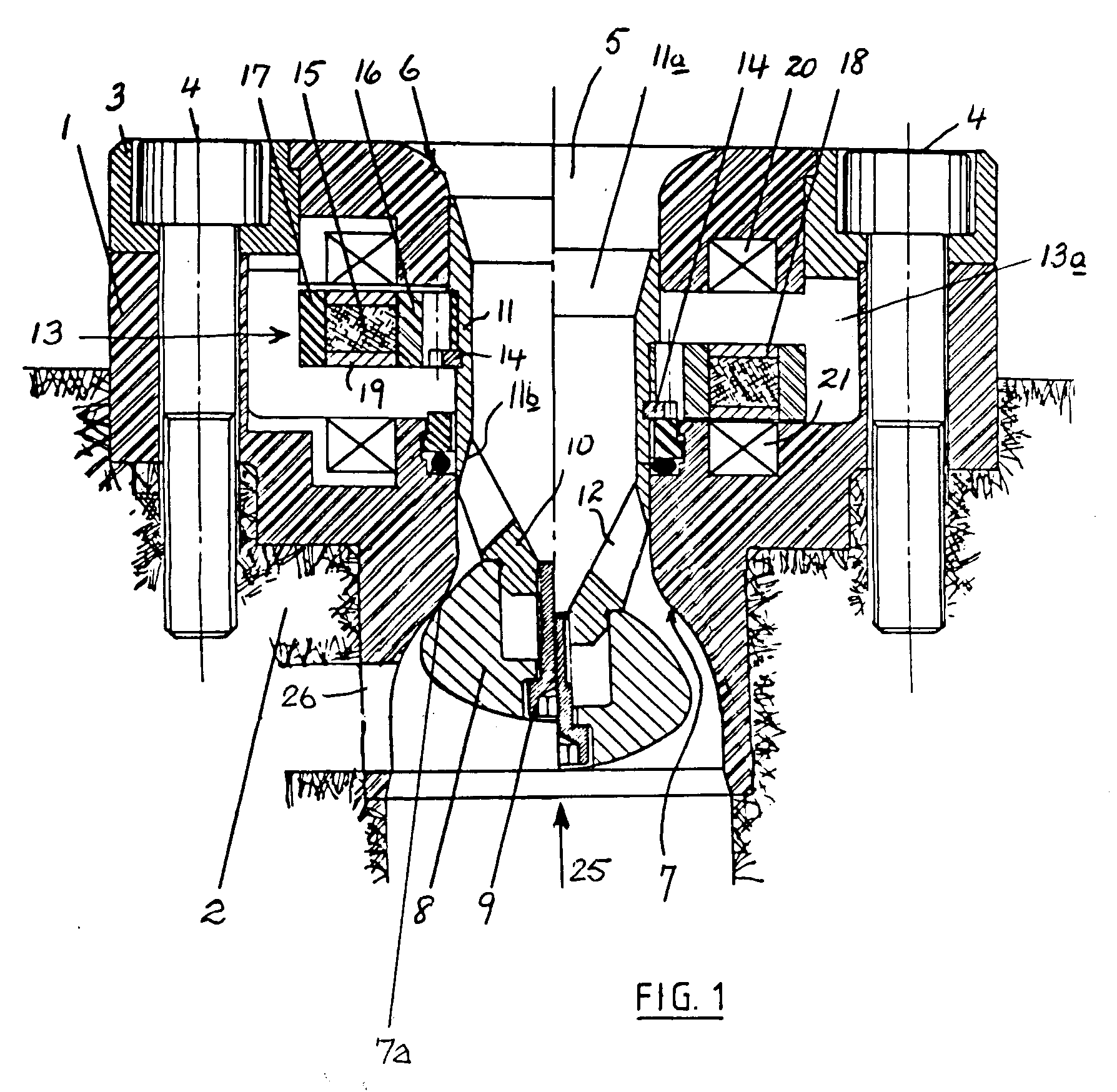
Figure 1 is a vertical sectional view of an electrically selectable poppet valve for
a multi-piston hydraulic pump, and
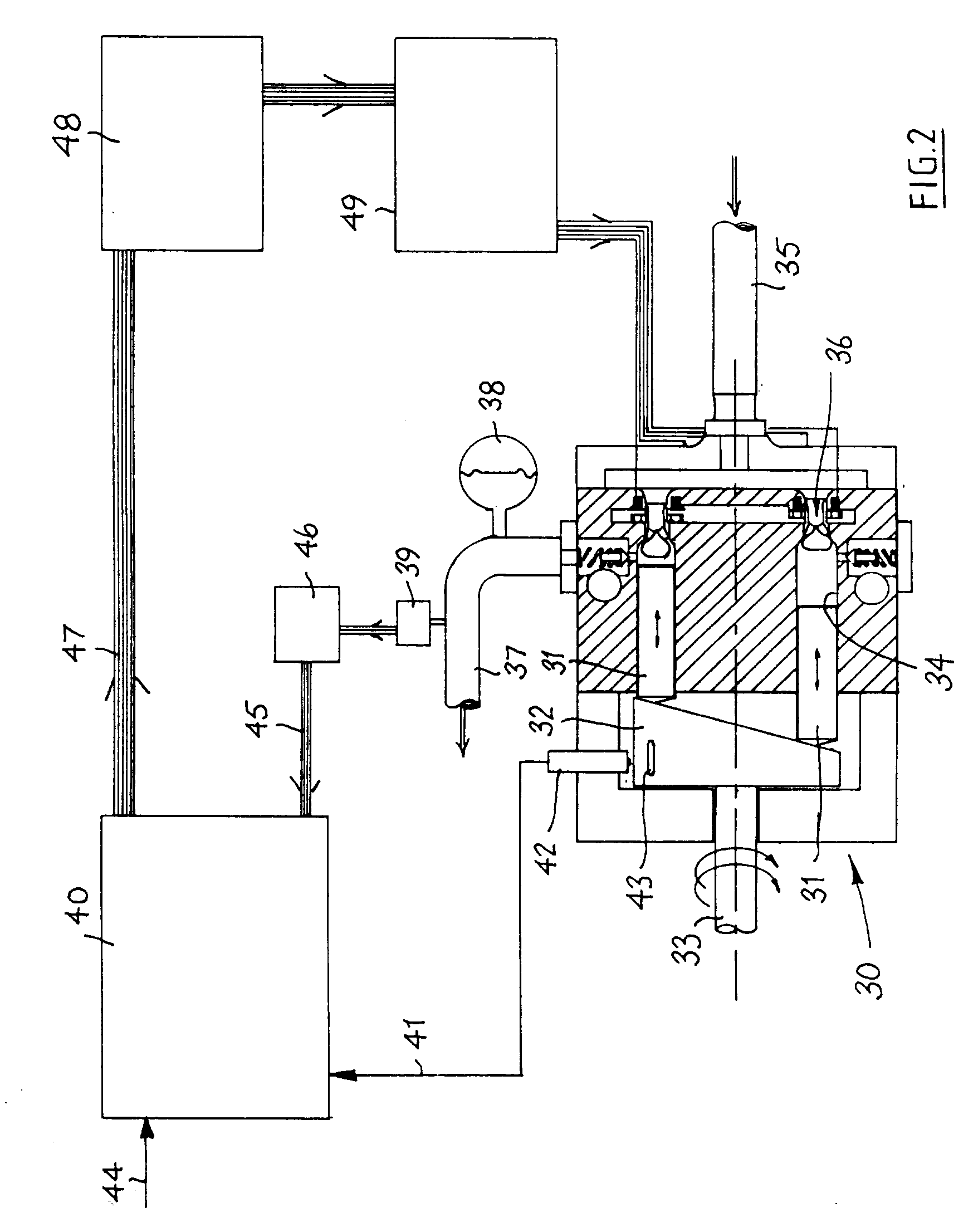
Figure 2 is a schematic view of an axial piston pump incorporating poppet valves of
the kind shown in Figure 1 together with control equipment for the several poppet
valves for performing the control method of this invention.
[0016] The left-hand half of Figure 1 illustrates the poppet valve in the closed position
while the right-hand half illustrates the valve in the open position.
[0017] Referring to Figure 1, a valve suitable for a multi-piston hydraulic pump (such as
an axial piston or ring-cam hydraulic pump) comprises a steel valve shell which is
adapted to be fixedly mounted within a cylinder body 2 of the pump through the intermediary
of a valve end cap 3 and associated cap screws 4.
[0018] The valve shell 1 has a bore 5 therethrough through which pumped hydraulic fluid
can pass from a profiled inlet 6 to a profiled outlet 7. The profiles of the inlet
to and outlet from the bore 5 are calculated to result in low fluid drag on passage
therethrough and the profiled outlet 7 includes a valve seat 7a for a poppet valve
8 made of surface-hardened steel.
[0019] The poppet valve 8 is of bulbous (i.e. part-elliptical) form and is securely attached
by means of a cap screw 9 to a rigid but hollow support 10. To ensure good sealing
even if there is some misalignment of the bulbous head in the outlet 7, the bulbous
head can be given a part spherical area in the vicinity of the sealing region of the
member which seals with the valve seat 7a. The support 10 is, in turn, integrally
connected to a non-ferromagnetic (e.g. phosphor bronze) flow tube 11 by means of a
thin septum constituted by rigid arms 12 which are angularly spaced from each other
to permit relatively unrestricted passage of hydraulic fluid into and out of the tube
11. The upstream and downstream ends of the flow tube 11 are internally chamfered
at 11a and 11b respectively.
[0020] The flow tube 11 with its associated poppet valve 8 is axially slidable relative
to the valve bore 5 between the two limit positions shown on the left and on the right.
[0021] An axially movable, bistable magnetic latch 13 is housed within a chamber 13a defined
within the valve shell 1. The latch 13 is fixedly connected to the flow tube 11 by
means of a spring circlip 14 and surrounds the latter.
[0022] The magnetic latch 13 is of annular form having a core 15 of a magnetic material
such as bonded or sintered rare earth material or neodymium-boron. The core 15 is
enclosed on its radially inner and outer sides by ferromagnetic pole rings 16 and
17 respectively and on its upper and lower faces by non-ferromagnetic guard rings
18 and 19 respectively. The core 15 is desirably magnetised in the radial direction
(e.g. so that the inner cylindrical surface thereof is the South pole and the outer
cylinder surface is the North pole).
[0023] The latch 13 is axially movable within its chamber 13a in a bistable manner under
the influence of upper and lower electromagnetic solenoid coils 20 and 21.
[0024] On appropriate electrical energisation of coil 20 or of both of the coils 20 and
21, the magnetic latch 13 is attracted to the energised coil 20 so that the poppet
valve 8 is moved into the closed or "enabled" position as shown in the left-hand side
of Figure 1 when magnetic lines link the upper coil 20 and the core 15 but is held
in the open or "disabled" position as shown on the right-hand side of Figure 1 when
magnetic flux lines link the lower coil 21 and the core 15. In the closed position
of the valve, hydraulic liquid flowing upwardly in the direction of the arrow 25 is
pumped into the high-pressure delivery side of the pump via a discharge port 26.
[0025] During each intake stroke of the piston, the poppet valve 8 is moved under the influence
of fluid flow into the open limit position where it latches. In this position liquid
can flow backwards and forwards through the annular passage defined between the bulbous
head of the valve 8 and the outlet 7, the hydraulic liquid being pumped back into
the low-pressure inlet manifold as the piston makes its discharge stroke with very
little loss of energy compared to that which would have been transferred to the liquid
had the valve 8 been closed.
[0026] As the poppet valve 8 and its associated magnetic latch 13 move into the open position,
the latch 13 can be made to contact a resilient end stop ring before it contacts the
coil 21 and its surrounding surfaces. Such a resilient end stop ring can be used to
cushion movement of the latch 13 into its fully open position.
[0027] The valve as described above has a response time which is fast enough so that it
can be closed at the appropriate moment in a pumping cycle of a multi-piston hydraulic
pump (e.g. a ring-cam pump) and this permits the pump to be operated with improved
performance, particularly with respect to control of pump displacement.
[0028] The lower solenoid coil 21 augments the action of the upper coil 20 during the movement
of the valve 8 into its closed position, the upper coil 20 attracting the latch 13
and the lower coil 21 repelling it.
[0029] Although a lower solenoid coil 21 is shown in Figure 1 this can be dispensed with,
and electromagnetic operation achieved with just the one coil 20 to hold the valve
member latched in the closed position. Latching in the open position is achieved by
the creation of a closed "lower" flux loop through the core 15 of the magnet and the
adjacent part of the shell 1 of the valve. When the coil 20 is energised the latching
flux holding the valve 8 open is diverted into a new circuit which includes the coil
20 so that the closed "lower" flux loop is destroyed in favour of an "upper" flux
loop that embraces the core 15 and draws the annular magnet up towards the coil 20.
Return of the valve member 8-11 to its open position will occur on the basis of liquid
flow-induced forces when the piston commences its next inlet stroke if the solenoid
coil 20 is then deenergised (or energised with a polarity repelling the core 15).
[0030] By virtue of the present invention which involves the electrical control of the inlet
valves of a reciprocating hydraulic pump, significant and advantageous consequences
arise which have not hitherto been possible with pumps having mechanically controlled
valves and this will now be described with reference to Figure 2.
[0031] Figure 2 shows a multi-piston pump 30 having a ring of pistons 31 driven by cam 32
as a driven cam shaft 33 rotates. Each piston 31 reciprocates in its cylinder 34 under
the influence of the rotating cam 32, drawing hydraulic liquid into the cylinders
31 from a low pressure manifold 35 via an electromagnetically controlled valve 36
of the kind shown in Figure 1 during each inlet stroke. At BDC each piston 31 reverses
direction of movement to start its delivery stroke, and if the respective valve 36
is closed, the hydraulic liquid is forced through the discharge port 26 into a high
pressure duct 37.
[0032] Mounted on the duct 37 is an output accumulator 38 (to smooth out pressure pulses
in the discharge from the pump) and a pressure measuring transducer 39.
[0033] In operation of the pump, a micro-processor unit 40 is used to control the opening
and closing of the valves 36. A once-per-revolution" shaft trigger signal is generated
on a line 41 (by a transducer 42 sensing passage of a "mark" 43 on the cam 32) and
is fed to the unit 40 with a digital input on line 44 related to pump output demand
and a digital input on line 45 from an analogue/digital converter 46 connected to
the transducer 39.
[0034] The unit 40 provides a digital output on line 47 which controls a bank of solenoid
drivers 49 via an isolating stage 48 (which can contain opto-isolators and transistor
drivers).
[0035] The microprocessor control unit 40 could contain several built-in algorithms which
enable the unit to compare the pump system demand characteristics with system feedback
and which outputs a signal on actuation of a cylinder and which causes the next cylinder
to reach BDC to become enabled should the system require its displacement of fluid.
This algorithm would desirably be tempered with a maximum rate of change algorithm
which would prevent sudden surges. Thus, the actual operating displacement characteristics
of the pump system are electromagnetically modified in accordance with the desired
demand displacement characteristics. The enabling pulse would then be sent to the
solenoid driver 49 after being timed by the noise algorithm in order to just close
the valve 36 of a module by the time the piston 31 in that module reached BDC. In
this way the shock wave generated by late valve closing is reduced.
[0036] The hardware illustrated in Figure 2 can operate for example in two different modes,
a flow control mode and a pressure control mode.
Flow Control Mode
[0037] The unit 40 keeps a running account of the displacement demand (from either a fixed
level or an external input such as an operator joystick) and the displacement produced
by the pump 30. At each cylinder enabling opportunity the unit 40 decides whether
the demand foreseen at the time of maximum effectiveness of the current cylinder justifies
its being enabled. This occurs if the displacement account will be at a deficit of
more than half of a cylinder. The accumulator 38 is sized so that a half cylinder
error will cause less than 10% variation in line pressure. This control method is,
in itself, open loop since no feedback is used. Feedback can be applied by positioning
a summing junction prior to the demand input 44 of the micro-processor unit 40.
Pressure Control Mode
[0038] In this situation the unit 40 attempts to maintain the required pressure on the output
line irrespective of the demand function. What it is actually doing is trying to keep
the accumulator volume as close to the zero error state as possible. To know the pumping
requirements the system has to calculate the flow from the output to the load. This
can be done by measuring the system pressure at two consecutive cylinder decision
intervals. The change in pressure equates to a change in accumulator volume which
indicates the displacement contribution from the accumulator 36 to the system. The
displacement delivered by the pump 30 during the time interval is calculated from
the records of the previously enabled cylinders. The output flow is the sum of pump
and accumulator flow (since the flow is incompressible for these purposes).
[0039] The output flow demand, the displacement from the committed cylinders and the displacement
to the accumulator (to restore it to the zero error position) are then combined to
allow a decision on whether to enable the current cylinder.
[0040] The microprocessor unit 40 can be equipped with different inputs including, for example:
1. Pump system demand characteristics for example from a potentiometer, a throttle
pedal (in the case of a pump used for vehicle drive), or a digital set-point.
2. Pump system feed back signals, for example from a motor speed sensor.
3. Noise sensor, for example an accelerometer, located on the pump casing.
[0041] It will be readily appreciated from the above that, because of the ability to control
the valve 36 of each piston and cylinder module of a pump within every cycle of the
pump, a pump, particularly a pump with a substantial number of cylinders, is capable
of more or less infinite variation in displacement. This differs from the stepped
type of variation possible in pumps heretofore.
[0042] It will, for example, be possible to programme the operation of a pump so that its
output varies from cycle to cycle. Alternatively, a pump can be divided into a number
of independently operable sections each comprising a plurality of cylinders. Each
section can be independently controlled as to displacement and used for operating
separate machines.
1. A method of controlling the output of a reciprocating fluid pump (30) connected to
a high pressure duct (37) and having a plurality of pumping chambers (34) each of
which has an inlet valve (36) with a valve member (8, 11) movable to an open limit
position to admit low pressure fluid to the chamber on an inlet stroke of the pump,
and movable to a closed position to prevent fluid again flowing past the valve member
and for a displacement volume of fluid to be ejected at high output pressure from
the chamber into the high pressure duct (37) on a discharge stroke of the pump, and
means (13) to control the opening and closing of the inlet valve members, characterised in that each inlet valve member is a poppet valve and in that electromagnetic means (20)
is provided for holding the poppet valve (8, 11) of at least one of the chambers in
its open limit position during at least one discharge stroke of the pump in said at
least one chamber, in that energisation of the electromagnetic means (20) is controlled
by a microprocessor unit (40) in response to at least one of output pressure of fluid
in the high pressure duct (37) and output displacement volume of fluid ejected from
the pump (30), and in that the response time of the valve (8, 11) is fast enough to
permit the microprocessor unit (40) to be programmed to enable or disable the next
chamber (31, 34) to pump depending on whether or not, in real time, output of the
pump (30) requires the displacement of the high pressure fluid said next chamber would
provide.
2. A method as claimed in claim 1, characterised in that the microprocessor unit (40) is programmed to enable or disable the next chamber
(34) to pump on the basis of the difference between a running account of a displacement
demand and the displacement produced by the pump (30), the decisions being based on
the demand projected forward in time so as to move the inlet valve (36) of the next
chamber (34) to pump to its closed position at the commencement of a discharge stroke
in that chamber if the displacement demand requires the displacement contribution
of that chamber.
3. A method as claimed in claim 1, characterised in that the microprocessor unit (40) is programmed to monitor the output pressure of the
ejected fluid and to enable or disable the next chamber (34) to pump on the basis
of maintaining a required pressure of fluid ejected from the pump (30).
4. A method as claimed in claim 3, characterised in that an output accumulator (38) is connected to the high pressure duct (37), to smooth
out pressure pulses in the high pressure duct (37) and in that the microprocessor
unit (40) is programmed to maintain the volume of fluid in the accumulator (38) as
close to a zero error state as possible.
5. A method as claimed in any preceding claim, characterised in that the electromagnetic means comprises a solenoid coil (20) fixedly mounted in a casing
(1) of the valve and an annular permanent magnet (15) surrounding the poppet valve
(11), the magnet moving relative to the coil in the opening/closing direction of the
poppet valve.
6. A method as claimed in claim 5, characterised in that energisation of the solenoid coil (20) is used to move the poppet valve to its closed
position, de-energisation allowing the poppet valve (8, 11) to move under the influence
of fluid flow-induced forces into its open limit position
7. A reciprocating fluid pump (30) connected to a high pressure duct (37) and having
a plurality of pumping chambers (34) each of which has an inlet valve (36) with a
valve member (8, 11) movable to an open limit position to admit low pressure fluid
to the chamber on an inlet stroke of the pump, and movable to a closed position to
prevent fluid against flowing past the valve member and for a displacement volume
of fluid to be ejected at high output pressure from the chamber into the high pressure
duct (37) on a discharge stroke of the pump, and means (13) to control the opening
and closing of the inlet valve members, characterised in that each inlet valve member is a poppet valve and in that electromagnetic means (20)
is provided for holding the poppet valve (8, 11) of at least one of the chambers in
its open limit position during at least one discharge stroke of the pump in said at
least one chamber, a microprocessor unit (40) controlling the energisation of the
electromagnetic means (20) in response to means sensing the output pressure of fluid
in the high pressure duct (37) or means sensing the output displacement volume of
fluid ejected from the pump (30), the microprocessor unit (40) being programmed to
enable or disable the next chamber (31, 34) to pump depending on whether or not, in
real time, output of the pump (30) requires the displacement of the high pressure
fluid said next chamber would provide.
8. A pump as claimed in claim 7, characterised in that the sealing surface of the poppet valve is formed on a bulbous head (8) of generally
elliptical shape, the head being connected to a tubular stem (11) having internally
chamfered ends (11a, 11b) and made of ferromagnetic material.
9. A pump as claimed in claim 8, characterised in that the electromagnetic means comprises a solenoid coil (20, 21) and cooperating annular
permanent magnet (15) connected to and surrounding the tubular stem of the valve.
10. A pump as claimed in claim 9, characterised in that the annular magnet (15) is magnetised in a radial direction.
11. A pump as claimed in claim 10, characterised in that the solenoid coil (20) draws the annular magnet (15) towards it on energisation of
the coil (20).
12. A pump as claimed in claim 11, characterised in that a second solenoid coil (21) is provided to augment the action of the first solenoid
coil (20).
1. Verfahren zur Regelung der Ausgangsleistung einer Flüssigkeitskolbenpumpe (30), die
mit einer Hochdruckleitung (37) verbunden ist und mehrere Pumpenkammern (34) aufweist,
von denen jede ein Einlaßventil (36) mit einem Ventilelement (8, 11) besitzt, das
sowohl in eine offene Grenzposition, um der Kammer bei einem Einlaßhub der Pumpe Niedrigdruckflüssigkeit
zuzuführen, als auch in eine geschlossene Position bewegbar ist, um ein Zurückströmen
der Flüssigkeit am Ventilelement vorbei zu verhindern und bei einem Auslaßhub der
Pumpe ein Flüssigkeitsverdrängungsvolumen bei hohem Ausgangsdruck aus der Kammer in
die Hochdruckleitung (37) auszutragen, sowie ein Mittel (13) umfaßt, um das Öffnen
und Schließen der Einlaßventilelemente zu regeln, dadurch gekennzeichnet, daß es sich bei jedem Einlaßventilelement um ein Tellerventil handelt, daß ein elektromagnetisches
Mittel (20) vorgesehen ist, um das Tellerventil (8, 11) von zumindest einer der Kammern
während zumindest eines Auslaßhubes der Pumpe in der genannten zumindest einen Kammer
in seiner offenen Grenzposition zu halten, daß die Erregung des elektromagnetischen
Mittels (20) von einer Mikroprozessoreinheit (40) in Abhängigkeit von zumindest einem
des Ausgangsdruckes der Flüssigkeit in der Hochdruckleitung (37) und des Ausgangsverdrängungsvolumens
der von der Pumpe (30) ausgetragenen Flüssigkeit geregelt wird, und daß die Ansprechzeit
des Ventiles (8, 11) kurz genug ist, um die Mikroprozessoreinheit (40) so zu programmieren,
daß in Abhängigkeit davon, ob die Ausgangsleistung der Pumpe (30) in Echtzeit ein
Verdrängen der aus der genannten nächsten Kammer verfügbaren Hochdruckflüssigkeit
erforderlich macht oder nicht, ein Pumpvorgang der nächsten Kammer (31, 34) ermöglicht
oder ausgeschlossen wird.
2. Verfahren nach Anspruch 1, dadurch gekennzeichnet, daß die Mikroprozessoreinheit (40) so programmiert ist, daß auf der Grundlage der Differenz
zwischen einer laufenden Erfassung eines Verdrängungsbedarfes und der von der Pumpe
(30) erzeugten Verdrängung ein Pumpvorgang der nächsten Kammer (34) ermöglicht oder
ausgeschlossen wird, wobei die Entscheidungen auf dem zeitlich vorausgeplanten Bedarf
basieren, um so das Einlaßventil (36) der für einen Pumpvorgang vorgesehenen nächsten
Kammer (34) am Beginn eines Auslaßhubes in jener Kammer in seine geschlossene Position
zu bewegen, falls der Verdrängungsbedarf die Beteiligung jener Kammer an der Verdrängung
erforderlich macht.
3. Verfahren nach Anspruch 1, dadurch gekennzeichnet, daß die Mikroprozessoreinheit (40) so programmiert ist, daß der Ausgangsdruck der ausgetragenen
Flüssigkeit überwacht und ein Pumpvorgang der nächsten Kammer (34) auf der Grundlage
der Aufrechterhaltung eines erforderlichen Druckes der von der Pumpe (30) ausgetragenen
Flüssigkeit ermöglicht oder ausgeschlossen wird.
4. Verfahren nach Anspruch 3, dadurch gekennzeichnet, daß ein Ausgangsspeicher (38) mit der Hochdruckleitung (37) verbunden ist, um Druckstöße
in der Hochdruckleitung (37) auszugleichen, und daß die Mikroprozessoreinheit (40)
so programmiert ist, daß das Flüssigkeitsvolumen im Speicher (38) auf der Basis eines
bestmöglichen Nullfehlerzustandes aufrechterhalten wird.
5. Verfahren nach einem der vorhergehenden Ansprüche, dadurch gekennzeichnet, daß das elektromagnetische Mittel eine fest in einem Gehäuse (1) des Ventiles montierte
Magnetspule (20) und einen das Tellerventil (11) umgebenden ringförmigen Dauermagneten
(15) umfaßt, wobei der Magnet sich im Verhältnis zur Spule in Öffnungs- bzw. Schließrichtung
des Tellerventiles bewegt.
6. Verfahren nach Anspruch 5, dadurch gekennzeichnet, daß die Erregung der Magnetspule (20) dazu benutzt wird, das Tellerventil in seine geschlossene
Position zu bewegen, und daß die Entregung es dem Tellerventil (8, 11) erlaubt, sich
unter dem Einfluß von durch die Flüssigkeitsströmung hervorgerufenen Kräften in seine
offene Grenzposition zu bewegen.
7. Flüssigkeitskolbenpumpe (30), die mit einer Hochdruckleitung (37) verbunden ist und
mehrere Pumpenkammern (34) aufweist, von denen jede ein Einlaßventil (36) mit einem
Ventilelement (8, 11) besitzt, das sowohl in eine offene Grenzposition, um der Kammer
bei einem Einlaßhub der Pumpe Niedrigdruckflüssigkeit zuzuführen, als auch in eine
geschlossene Position bewegbar ist, um ein Zurückströmen der Flüssigkeit am Ventilelement
vorbei zu verhindern und bei einem Auslaßhub der Pumpe ein Flüssigkeitsverdrängungsvolumen
bei hohem Ausgangsdruck aus der Kammer in die Hochdruckleitung (37) auszutragen, sowie
ein Mittel (13) umfaßt, um das Öffnen und Schließen der Einlaßventilelemente zu regeln,
dadurch gekennzeichnet, daß es sich bei jedem Einlaßventilelement um ein Tellerventil handelt, daß ein elektromagnetisches
Mittel (20) vorgesehen ist, um das Tellerventil (8, 11) von zumindest einer der Kammern
während zumindest eines Auslaßhubes der Pumpe in der genannten zumindest einen Kammer
in seiner offenen Grenzposition zu halten, und daß eine Mikroprozessoreinheit (40)
die Erregung des elektromagnetischen Mittels (20) in Abhängigkeit von einem Mittel
zum Abtasten des Ausgangsdruckes der Flüssigkeit in der Hochdruckleitung (37) oder
eines Mittels zum Abtasten des Ausgangsverdrängungsvolumens der von der Pumpe (30)
ausgetragenen Flüssigkeit regelt, wobei die Mikroprozessoreinheit (40) so programmiert
ist, daß in Abhängigkeit davon, ob die Ausgangsleistung der Pumpe (30) in Echtzeit
ein Verdrängen der aus der genannten nächsten Kammer verfügbaren Hochdruckflüssigkeit
erforderlich macht oder nicht, ein Pumpvorgang der nächsten Kammer (31, 34) ermöglicht
oder ausgeschlossen wird.
8. Pumpe nach Anspruch 7, dadurch gekennzeichnet, daß die Dichtfläche des Tellerventiles an einem kugeligen Kopf (8) von im allgemeinen
elliptischer Form ausgebildet ist, wobei der Kopf mit einem rohrförmigen Schaft (11)
verbunden ist, der innen abgeschrägte Enden (11a, 11b) aufweist und aus ferromagnetischem
Material besteht.
9. Pumpe nach Anspruch 8, dadurch gekennzeichnet, daß das elektromagnetische Mittel eine Magnetspule (20, 21) und einen damit zusammenwirkenden
ringförmigen Dauermagneten (15) umfaßt, der mit dem rohrförmigen Schaft des Ventiles
verbunden ist und diesen umgibt.
10. Pumpe nach Anspruch 9, dadurch gekennzeichnet, daß die Magnetisierung des ringförmigen Magneten (15) in radialer Richtung erfolgt.
11. Pumpe nach Anspruch 10, dadurch gekennzeichnet, daß die Magnetspule (20) den ringförmigen Magneten (15) bei Erregung der Spule (20) anzieht.
12. Pumpe nach Anspruch 11, dadurch gekennzeichnet, daß eine zweite Magnetspule (21) vorgesehen ist, um die Wirkung der ersten Magnetspule
(20) zu verstärken.
1. Méthode de contrôle de la sortie d'une pompe à fluide alternative (30) reliée à une
conduite à haute pression (37) et ayant une pluralité de chambres de pompage (34)
dont chacune a une soupape d'admission (36) avec un élément de soupape (8, 11) mobile
jusqu'à une position limite ouverte pour admettre un fluide à basse pression dans
la chambre lors d'une course d'admission de la pompe, et mobile jusqu'à une position
fermée pour empêcher le fluide de s'écouler le long de l'élément de soupape et pour
expulser de la chambre un volume déplacé de fluide avec une haute pression de sortie
dans la conduite à haute pression (37) lors d'une course d'évacuation de la pompe,
et des moyens (13) pour contrôler l'ouverture et la fermeture des éléments de soupape
d'admission, caractérisée en ce que chaque élément de soupape d'admission est une soupape en champignon et en ce que
des moyens électromagnétiques (20) sont prévus pour maintenir la soupape en champignon
(8, 11) d'au moins une des chambres dans sa position limite ouverte pendant au moins
une course d'évacuation de la pompe dans ladite au moins une chambre, en ce que l'excitation
des moyens électromagnétiques (20) est contrôlée par une unité de microprocesseur
(40) en réponse à au moins une pression de sortie du fluide dans la conduite à haute
pression (37) et/ou un volume déplacé de sortie du fluide expulsé de la pompe (30),
et en ce que le temps de réponse de la soupape (8, 11) est assez rapide pour permettre
à l'unité de microprocesseur (40) d'être programmée pour permettre ou empêcher la
chambre suivante (31, 34) de pomper selon que, en temps réel, la sortie de la pompe
(30) requiert ou non le déplacement du fluide à haute pression que ladite chambre
suivante fournirait.
2. Méthode suivant la revendication 1, caractérisée en ce que l'unité de microprocesseur (40) est programmée pour permettre à la chambre suivante
(34) de pomper ou l'en empêcher sur la base de la différence entre un comptage permanent
d'une demande de déplacement et le déplacement produit par la pompe (30), les décisions
étant basées sur la projection de la demande en avant dans le temps de façon à déplacer
la soupape d'admission (36) de la chambre suivante (34) pour pomper jusqu'à sa position
fermée au commencement d'une course d'évacuation dans cette chambre si la demande
de déplacement requiert la contribution de déplacement de cette chambre.
3. Méthode suivant la revendication 1, caractérisée en ce que l'unité de microprocesseur (40) est programmée pour surveiller la pression de sortie
du fluide expulsé et pour permettre à la chambre suivante (34) de pomper ou l'en empêcher
sur la base du maintien d'une pression requise du fluide expulsé de la pompe (30).
4. Méthode suivant la revendication 3, caractérisée en ce qu'un accumulateur de sortie (38) est relié à la conduite à haute pression (37), pour
lisser les impulsions de pression dans la conduite à haute pression (37) et en ce
que l'unité de microprocesseur (40) est programmée pour maintenir le volume de fluide
dans l'accumulateur (38) aussi près que possible du niveau d'erreur de zéro.
5. Méthode suivant l'une quelconque des revendications précédentes, caractérisée en ce que les moyens électromagnétiques comprennent une bobine de solénoïde (20) montée fixement
dans un boîtier (1) de la soupape et un aimant permanent annulaire (15) entourant
la soupape en champignon (11), l'aimant se déplaçant par rapport à la bobine dans
la direction ouverture/fermeture de la soupape en champignon.
6. Méthode suivant la revendication 5, caractérisée en ce que l'excitation de la bobine de solénoïde (20) est utilisée pour déplacer la soupape
en champignon jusqu'à sa position fermée, une désexcitation permettant à la soupape
en champignon (8, 11) de se déplacer sous l'influence de forces induites par le courant
de fluide dans sa position limite ouverte.
7. Pompe à fluide alternative (30) reliée à une conduite à haute pression (37) et ayant
une pluralité de chambres de pompage (34) dont chacune a une soupape d'admission (36)
avec un élément de soupape (8, 11) mobile jusqu'à une position limite ouverte pour
admettre un fluide à basse pression dans la chambre lors d'une course d'admission
de la pompe, et mobile jusqu'à une position fermée pour empêcher le fluide de s'écouler
le long de l'élément de soupape et pour expulser de la chambre un volume déplacé de
fluide avec une haute pression de sortie dans la conduite à haute pression (37) lors
d'une course d'évacuation de la pompe, et des moyens (13) pour contrôler l'ouverture
et la fermeture des éléments de soupape d'admission, caractérisée en ce que chaque élément de soupape d'admission est une soupape en champignon et en ce que
des moyens électromagnétiques (20) sont prévus pour maintenir la soupape en champignon
(8, 11) d'au moins une des chambres dans sa position limite ouverte pendant au moins
une course d'évacuation de la pompe dans ladite au moins une chambre, une unité de
microprocesseur (40) contrôlant l'excitation des moyens électromagnétiques (20) en
réponse à des moyens de détection de la pression de sortie du fluide dans la conduite
à haute pression (37) ou à des moyens de détection du volume déplacé de sortie du
fluide expulsé de la pompe (30), l'unité de microprocesseur (40) étant programmée
pour permettre à la chambre suivante (31, 34) de pomper ou l'en empêcher selon que,
en temps réel, la sortie de la pompe (30) requiert ou non le déplacement du fluide
à haute pression que ladite chambre suivante fournirait.
8. Pompe suivant la revendication 7, caractérisée en ce que la surface d'étanchéité de la soupape en champignon est formée sur une tête en forme
de bulbe (8) de forme généralement elliptique, la tête étant reliée à une queue tubulaire
(11) ayant des extrémités intérieurement chanfreinées (11a, 11b) et constituée de
matière ferro-magnétique.
9. Pompe suivant la revendication 8, caractérisée en ce que les moyens électromagnétiques comprennent une bobine de solénoïde (20, 21) et un
aimant permanent annulaire coopérant (15) relié à et entourant la queue tubulaire
de la soupape.
10. Pompe suivant la revendication 9, caractérisée en ce que l'aimant annulaire (15) est aimanté dans une direction radiale.
11. Pompe suivant la revendication 10, caractérisée en ce que la bobine de solénoïde (20) attire l'aimant annulaire (15) vers elle lors de l'excitation
de la bobine (20).
12. Pompe suivant la revendication 11, caractérisée en ce qu'une deuxième bobine de solénoïde (21) est prévue pour renforcer l'action de la première
bobine de solénoïde (20).