|
(11) | EP 0 365 270 B1 |

| (12) | EUROPEAN PATENT SPECIFICATION |
|
|
| (54) |
Processing seismic data Verarbeitung seismischer Daten Traitement de données sismiques |
|
|
|||||||||||||||||||||||||||||||
| Note: Within nine months from the publication of the mention of the grant of the European patent, any person may give notice to the European Patent Office of opposition to the European patent granted. Notice of opposition shall be filed in a written reasoned statement. It shall not be deemed to have been filed until the opposition fee has been paid. (Art. 99(1) European Patent Convention). |
[0002] The use of a slanted cable for gathering marine seismic data has been proposed by Ray et al in U.S. Patent 4,353,121, which issued on October 5, 1982. A primary advantage of using a slanted cable is that it permits reduction, in seismic data, of noise resulting from ghost reflections. In marine data gathering operations, a signal from a seismic source progresses downwardly through the water until it reaches a reflecting interface. The reflected signal then travels upwardly to the seismic detectors positioned along the cable and to the water surface. The signal is then reflected downwardly by the water-air interface and is detected again by the seismic detectors. This reflection is referred to as the ghost reflection. The detection of the ghost reflection along with the primary reflection results in a distorted waveform compared to the waveform of the source impulse. The interrelated effect of the ghost reflection with the primary reflection results in interference cancellation at some frequencies and augmentation at other frequencies.
[0003] In the Ray et al disclosure, the cable was deployed at a slope of about two degrees. The primary reflection from each seismic interface and its corresponding ghost reflection is received by each detector and recorded on a field recorder. For each reflecting interface, because of the slope of the cable, the time gap between the detection of the primary and ghost reflections becomes greater, the further the detector is from the source. After typical data processing operations are performed, such as demultiplexing, gain recovery and sorting into common depth point files, static time shifts are applied to correct the primary arrivals to a datum, usually the surface of the water. Then for each interface, the velocity for the primary reflections is determined, the NMO (normal moveout) correction is applied and the primary reflections are time aligned and stacked in the time domain, thereby producing an enhanced primary stack while not emphasizing the individual ghost signals since they are not time aligned.
[0004] The data is then processed so that static corrections are also applied to correct the ghost arrivals to a datum and the phase of such arrivals is reversed. In a manner similar to stacking of the primary arrivals, the ghost reflections are time aligned and stacked in the time domain, thereby producing an augmented ghost stack while not enhancing the primary stack since they are not time aligned. The two stacks are then summed.
[0005] The static time shift method of Ray et al deliberately corrects recorded seismic data only for the time offset resulting from the vertical displacement of the detectors from the surface. Thus, this method deliberately does not correct for time offset resulting from the various horizontal displacements of the detectors. Thus, when the aligned data is stacked, signals directed at the detectors at angles other than the vertical are attenuated, and this is the object of Ray et al.
[0006] According to the present invention, there is provided a method of marine seismic exploration, comprising processing seismic data, recorded utilizing detectors (18a . . . x) positioned on a cable (16) towed behind a vessel (10) at an angle to the horizontal, so as to remove a time offset component in the recorded data resulting from the cable slant, characterised in that the method also removes the time offset of reflections arriving with angular orientations other than vertical by performing a two dimensional Fourier Transform on the recorded data, and by correcting for the cable slant in the horizontal wavenumber domain.
[0007] The data may also be processed to align the ghost signals, thereby misaligning the primary signals. The two resulting data sets may then be summed.
[0008] The step of processing may involve transforming shot gather seismic data from time-offset domain data to horizontal wavenumber-frequency domain data. The article by D. Hale entitled "Dip Moveout by Fourier Transform" in Geophysics, Vol. 49, No. 6, June 1984, pages 741-757, discloses a similar processing step although not for use in correcting for time offsets due to cable slant.
[0009] It will be apparent that the method can be operated to time shift all events of data recorded with a slanted cable to make them appear as if recorded by a flat cable, regardless of direction of arrival.
[0010] For a better understanding of the present invention and as to how the same may be carried into effect, reference will now be made, by way of example, to the accompanying drawings in which:
Figure 1 shows the gathering of marine seismic data;
Figure 2 shows differences in time offset, for a flat cable and a slanting cable, of signals reaching the cable at different wave front orientations;
Figure 3 shows a section of seismic data processed by the static method of the prior art; and
Figure 4 shows a section of seismic data processed by a method embodying the present invention.
[0011] Figure 1 shows a marine seismic vessel 10 moving on surface 12 of a body of water. An energy source 14 is towed by vessel 10 for imparting seismic signals downwardly into the water. The source most frequently used in marine seismic exploration at the present time is the air gun, although other sources are also utilized. Also shown towed by the vessel is a cable or streamer 16 along which are located a plurality of detectors, normally hydrophone arrays, 18a, 18b, ..., 18x. The cable slopes downwardly from its front end to its back end by an angle, x, with respect to the horizontal which may typically be between 2 and 4 degrees.
[0012] Also shown in Figure 1 are two plane waves A and B. Plane wave A represents a seismic signal approaching the cable from a direction directly beneath the cable. Plane wave B represents a seismic signal approaching the cable at a different angle. The signals detected by the hydrophone array will be approaching the cable from varying angles depending on the distance from the source to the detector, the depth of the reflecting interface and the dip angle of the reflecting interface.
[0013] The amount of time offset between the time a seismic signal is detected by the slanted cable and the time the signal would have been detected by a flat cable is a function of the angle at which the signal is approaching the cable and the difference in depth of the slanted cables vs. a flat cable. Figure 2 illustrates the variation in this offset for the primary signal, where ΔtA shows the difference in the offset for a flat cable vs. a slanted cable for plane wave A and ΔtB represents the difference in the offset for a flat cable vs. a slanted cable for plane wave B.
[0014] Seismic data is acquired and recorded in the same manner as if the cable were substantially flat. Standard preprocessing steps are performed such as demultiplexing and trace gain treatment. Data is formatted into shot gathers and each data gather is transformed from the time offset domain to the frequency horizontal wavenumber domain by performing a two dimensional Fourier Transform. In common mathematical symbols this transformation is written as:
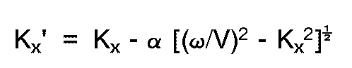
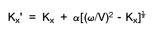
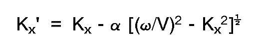
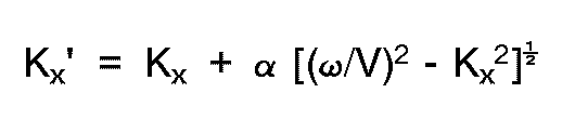
Upward traveling events in the transformed data set are made to appear as if recorded by a flat cable by a mapping of the horizontal wavenumber kx to a new horizontal wavenumber kx′. The mapping function is:
where
v = speed of sound in the water
ω = angular frequency
α = angle of cable slant with reference to the horizontal.
This resulting data set will be referred to as Data Set A.
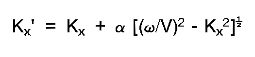
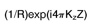
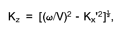
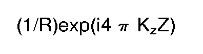
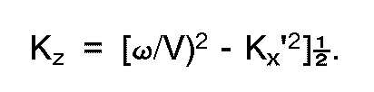
[0015] Similarly, the downwardly traveling events or ghost signals are made to appear as if recorded by a flat cable by the mapping function:
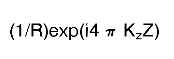
The preceding data set, which may be referred to as Data Set B, is then processed further so as to make the downward traveling (ghost) events align with the upgoing events in Data Set A. The processing is performed by multiplying the function by the factor (1/R)exp(i4πkzZ)
where:
Z = the flat cable depth to which the data is being transformed
R = reflection coefficient of the water surface
This resulting data set will be referred to as Data Set C.
[0016] Data Sets A and C may then be summed, and the summed data transformed back to time-offset data by performing an inverse two dimensional Fourier Transform, normally represented as
Normal data processing, such as normal moveout correction and stacking, is then performed.
[0017] Alternatively, Data Sets A and C may be individually inverse transformed back to time-offset data. Typically, the two data sets would then be analyzed for velocity, corrected for normal moveout (NMO) and stacked. The two stacked data sets may then be summed. As another alternative, after Data Sets A and B are transformed back to time-offset data, the Data Sets may be summed and then stacked.
[0018] The method can be performed utilizing a digital computer of a type typically used in the industry. The writing of computer programs to perform the method is within the ability of one of ordinary skill in the art.
[0019] Figure 3 shows a section of data processed utilizing the static time shift method of the prior art. Figure 4 shows the same data processed utilizing the above described method. The figures show, in the region designated as "A", the direct arrival of the seismic signal. The direct arrival is included in addition to other refracted or reflected signals because the direct arrival is an essentially horizontally travelling signal and the difference between the prior art processing and the processing of the current invention is more clearly visible. It can be observed from Figures 3 and 4 that there is relatively little difference in the near-offset traces, where the depth of the slanted cable is little different from the depth of a flat cable. For far-offset traces, however, where the water depth of the slanted cable increases, the difference in the data is more evident, with the data processed using a method embodying the present invention displaying a greater bandwidth than the data processed by the prior art static method.
1. A method of marine seismic exploration, comprising processing seismic data, recorded
utilizing detectors (18a . . . x) positioned on a cable (16) towed behind a vessel
(10) at an angle to the horizontal, so as to remove a time offset component in the
recorded data resulting from the cable slant, characterised in that the method also
removes the time offset of reflections arriving with angular orientations other than
vertical by performing a two dimensional Fourier Transform on the recorded data, and
by correcting for the cable slant in the horizontal wavenumber domain.
2. A method according to claim 1 wherein the processing step comprises transforming shot
gather seismic data from time-offset domain data to horizontal wavenumber-frequency
domain data, mapping horizontal wave numbers of events in the transformed data to
new horizontal wavenumbers so that events appear as if recorded by a horizontal cable
thereby generating remapped data, and transforming said remapped data back to the
time-offset domain.
3. A method according to claim 2 wherein said horizontal wavenumbers of events in the
transformed data are mapped to said new horizontal wavenumbers such that a first set
of data, Data Set A, is generated in which upwardly travelling events appear as if
recorded by a horizontal cable, and a second set of data, Data Set B, is generated
in which downwardly travelling events appear as if recorded by a horizontal cable.
4. A method according to claim 3, comprising processing Data Set B so as to make the
downwardly travelling events align with upgoing events in Data Set A, thereby generating
a third set of data, Data Set C.
5. A method according to claim 4, comprising summing Data Sets A and C, and inverse transforming
the summation of data sets A and C from the horizontal wavenumberfrequency domain
to the time-offset domain.
6. A method according to claim 4, comprising inverse transforming Data Sets A and C separately
from the horizontal wavenumber-frequency domain to the time-offset domain and summing
Data Sets A and C.
7. A method according to any one of claims 3 to 6 wherein said upwardly travelling events
are made to appear as if recorded by a horizontal cable by mapping horizontal wavenumbers
to new horizontal wavenumbers utilizing the relation
where:
Kx' = new horizontal wavenumber
Kx = horizontal wavenumber
V = speed of sound in the water
α = angle of cable slant with reference to the horizontal
ω = angular frequency
where:
Kx' = new horizontal wavenumber
Kx = horizontal wavenumber
V = speed of sound in the water
α = angle of cable slant with reference to the horizontal
ω = angular frequency
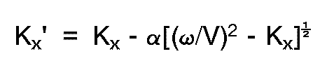
8. A method according to any one of claims 3 to 6 wherein said downwardly travelling
events are made to appear as if recorded by a horizontal cable by mapping horizontal
wavenumbers to new horizontal wavenumbers utilizing the relation
where:
Kx' = new horizontal wavenumber
Kx = horizontal wavenumber
V = speed of sound in water
α = angle of cable slant with reference to the horizontal
ω = angular frequency.
where:
Kx' = new horizontal wavenumber
Kx = horizontal wavenumber
V = speed of sound in water
α = angle of cable slant with reference to the horizontal
ω = angular frequency.
9. A method according to claim 4 or any one of claims 5 to 8 when appended to claim 4,
wherein said Data Set B is processed so as to make the downwardly travelling events
align with upgoing events by multiplying by the factor:
where:
Z = the flat cable depth to which the data is being transformed
R = reflection coefficient of the water surface

where:
ω = angular frequency
V = speed of sound in water
Kx' = new horizontal wavenumber
where:
Z = the flat cable depth to which the data is being transformed
R = reflection coefficient of the water surface
where:
ω = angular frequency
V = speed of sound in water
Kx' = new horizontal wavenumber
10. A method according to any one of the preceding claims wherein said cable is towed
at an angle of between two and four degrees to the horizontal.
11. A method according to any one of the preceding claims comprising
recording seismic data utilizing detectors (18a...x) positioned on a cable (16) towed behind a vessel (10) at substantially a determinable angle (α).
recording seismic data utilizing detectors (18a...x) positioned on a cable (16) towed behind a vessel (10) at substantially a determinable angle (α).
1. Verfahren zur seismischen Meererkundung, umfassend das Verarbeiten der seismischen
Daten, die mit Detektoren (18a . . . x) aufgezeichnet wurden, die auf einem Kabel
(16) angeordnet sind, das hinter einem Schiff (10) unter einem Winkel gegen die Waagrechte
geschleppt wird, um damit eine Zeitverschiebungskomponente in den aufgezeichneten
Daten zu entfernen, die von der Kabelneigung verursacht wird, dadurch gekennzeichnet,
daß das Verfahren auch die Zeitverschiebung von Reflexionen entfernt, die unter von
der Senkrechten abweichenden Winkelrichtungen ankommen, indem die aufgezeichneten
Daten einer zweidimensionalen Fouriertransformation unterworfen werden und die Kabelneigung
im horizontalen Wellenzahlbereich korrigiert wird.
2. Verfahren nach Anspruch 1, wobei der Verarbeitungsschritt umfaßt das Transformieren
der seismischen Daten, die zu einem shot gather gehören, aus Daten im Zeitverschiebungsbereich
in Daten im horizontalen Wellenzahl-Frequenzbereich und das Abbilden der horizontalen
Wellenzahlen in neue, horizontale Wellenzahlen, so daß Ereignisse so erscheinen, als
wären sie von einem waagrechten Kabel aufgezeichnet und dabei abgebildete Daten erzeugt
werden, und das Zurücktransformieren dieser abgebildeten Daten in den Zeitverschiebungsbereich.
3. Verfahren nach Anspruch 2, wobei die horizontalen Wellenzahlen von Ereignissen in
den transformierten Daten auf neue, horizontale Wellenzahlen abgebildet werden, so
daß ein erster Datensatz erzeugt wird, der Datensatz A, in dem nach oben laufende
Ereignisse erscheinen, als ob sie von einem waagrechten Kabel aufgezeichnet wären,
und ein zweiter Datensatz erzeugt wird, der Datensatz B, in dem nach unten laufende
Ereignisse erscheinen, als ob sie von einem waagrechten Kabel aufgezeichnet wären.
4. Verfahren nach Anspruch 3, umfassend die Verarbeitung des Datensatzes B auf eine Weise,
daß die nach unten laufenden Ereignisse mit den nach oben laufenden Ereignissen im
Datensatz A ausgerichtet werden, so daß ein dritter Datensatz erzeugt wird, der Datensatz
C.
5. Verfahren nach Anspruch 4, umfassend das Addieren der Datensätze A und C und das inverse
Fouriertransformieren der Summe der Datensätze A und C aus dem horizontalen Wellenzahl-Frequenzbereich
in den Zeitverschiebungsbereich.
6. Verfahren nach Anspruch 4, umfassend das inverse, voneinander getrennte Transformieren
der Datensätze A und C aus dem horizontalen Wellenzahlbereich in den Zeitverschiebungsbereich
und das Addieren der Datensätze A und C.
7. Verfahren nach irgendeinem der Ansprüche 3 bis 6, wobei man die nach oben laufenden
Ereignisse so erscheinen läßt, als ob sie von einem waagrechten Kabel aufgezeichnet
wären, indem die horizontalen Wellenzahlen mit der Beziehung
auf neue, horizontale Wellenzahlen abgebildet werden, wobei gilt:
Kx' = neue, horizontale Wellenzahl,
Kx = horizontale Wellenzahl,
V = Schallgeschwindigkeit in Wasser,
α = Winkel der Kabelneigung gegen die Waagrechte und
ω = Winkelfrequenz.
auf neue, horizontale Wellenzahlen abgebildet werden, wobei gilt:
Kx' = neue, horizontale Wellenzahl,
Kx = horizontale Wellenzahl,
V = Schallgeschwindigkeit in Wasser,
α = Winkel der Kabelneigung gegen die Waagrechte und
ω = Winkelfrequenz.
8. Verfahren nach irgendeinem der Ansprüche 3 bis 6, wobei man die nach unten laufenden
Ereignisse so erscheinen läßt, als ob sie von einem waagrechten Kabel aufgezeichnet
wären, indem die horizontalen Wellenzahlen mit der Beziehung
auf neue, horizontale Wellenzahlen abgebildet werden, wobei gilt:
Kx' = neue, horizontale Wellenzahl,
Kx = horizontale Wellenzahl,
V = Schallgeschwindigkeit in Wasser,
α = Winkel der Kabelneigung gegen die Waagrechte und
ω = Winkelfrequenz.
auf neue, horizontale Wellenzahlen abgebildet werden, wobei gilt:
Kx' = neue, horizontale Wellenzahl,
Kx = horizontale Wellenzahl,
V = Schallgeschwindigkeit in Wasser,
α = Winkel der Kabelneigung gegen die Waagrechte und
ω = Winkelfrequenz.
9. Verfahren nach Anspruch 4 oder irgendeinem der Ansprüche 5 bis 8 in Verbindung mit
Anspruch 4, wobei der Datensatz B so verarbeitet wird, daß die nach unten laufenden
Ereignisse mit den nach oben laufenden Ereignissen ausgerichtet werden, indem sie
mit dem Faktor
multipliziert werden,
wobei gilt:
Z = Tiefe des waagrechten Kabels, auf die die Daten transformiert werden,
R = Reflexionskoeffizient der Wasseroberfläche,
und:
ω = Winkelfrequenz,
V = Schallgeschwindigkeit in Wasser und
Kx' = neue, horizontale Wellenzahl.
multipliziert werden,
wobei gilt:
Z = Tiefe des waagrechten Kabels, auf die die Daten transformiert werden,
R = Reflexionskoeffizient der Wasseroberfläche,
und:
ω = Winkelfrequenz,
V = Schallgeschwindigkeit in Wasser und
Kx' = neue, horizontale Wellenzahl.
10. Verfahren nach irgendeinem der vorhergehenden Ansprüche, wobei das Kabel unter einem
Winkel von zwei bis vier Grad gegen die Waagrechte geschleppt wird.
11. Verfahren nach irgendeinem der vorhergehenden Ansprüche, umfassend das Aufzeichnen
von seismischen Daten mit Detektoren (18a...x), die auf einem Kabel (16) angeordnet
sind, das hinter einem Schiff (10) unter einem im wesentlichen festlegbaren Winkel
(α) geschleppt wird.
1. Un procédé d'exploration sismique en mer, comprenant un traitement de données sismiques
enregistrées en utilisant des détecteurs (18a ... x) placés sur un câble (16) tiré
derrière un navire (10) en faisant un angle par rapport à l'horizontale, afin d'éliminer
une composante de décalage de temps dans les données enregistrées résultant de l'inclinaison
du câble, caractérisé en ce que le procédé élimine également le décalage de temps
de réflexions arrivant avec des orientations angulaires autres que verticales en effectuant
une transformée de Fourrier bi-dimensionnelle sur les données enregistrées, et en
effectuant une correction pour l'inclinaison du câble dans le domaine des nombres
d'ondes horizontales.
2. Un procédé selon la revendication 1, dans lequel l'opération de traitement comprend
le fait de transformer des données sismiques recueillies par explosion à partir de
données de domaines décalées dans le temps jusqu'à des données de domaines de fréquence
de nombres d'ondes horizontales, dresser la carte de nombres d'ondes horizontales
d'évènements dans les données transformées pour donner de nouveaux nombres d'ondes
horizontales de sorte que les évènements apparaissent comme avoir été enregistrés
par un câble horizontal en créant ainsi des données redressées de carte, et transformer
en retour lesdites données redressées de carte dans le domaine décalé dans le temps.
3. Un procédé selon la revendication 2, dans lequel on dresse la carte desdits nombres
d'ondes horizontales d'évènements dans les données transformées pour donner lesdits
nouveaux nombres d'ondes horizontales de sorte qu'on forme un premier jeu de données,
Jeu de Données A, dans lequel des évènements défilant vers le haut apparaissent comme
avoir été enregistrés par un câble horizontal et on forme un second jeu de données,
Jeu de Données B, dans lequel des évènements défilant vers le bas apparaissent comme
avoir été enregistrés par un câble horizontal.
4. Un procédé selon la revendication 3, comprenant le fait de traiter le Jeu de Données
B de manière à faire que les évènements défilant vers le bas s'alignent avec des évènements
allant vers le haut dans le Jeu de Données A, de manière ainsi à produire un troisième
jeu de données, Jeu de Données C.
5. Un procédé selon la revendication 4, comprenant la sommation des Jeux de Données A
et C, et la transformation inverse de la sommation des jeux de données A et C du domaine
de fréquence de nombres d'ondes horizontales au domaine décalé dans le temps.
6. Un procédé selon la revendication 4, comprenant la transformation inverse des Jeux
de Données A et C de manière séparée du domaine de fréquence de nombres d'ondes horizontales
au domaine décalé dans le temps et la sommation des Jeux de Données A et C.
7. Un procédé selon l'une quelconque des revendications 3 à 6, dans lequel les événements
à défilement vers le haut sont amenés à apparaître comme ayant été enregistrés par
un câble horizontal en traçant la carte des nombres d'ondes horizontales pour donner
de nouveaux nombres d'ondes horizontales en utilisant la relation
où :
Kx' = nouveau nombre d'ondes horizontales
Kx = nombre d'ondes horizontales
V = vitesse du son dans l'eau
α = angle d'inclinaison du câble par rapport à l'horizontale
ω = fréquence angulaire
où :
Kx' = nouveau nombre d'ondes horizontales
Kx = nombre d'ondes horizontales
V = vitesse du son dans l'eau
α = angle d'inclinaison du câble par rapport à l'horizontale
ω = fréquence angulaire
8. Un procédé selon l'une quelconque des revendications 3 à 6, dans lequel lesdits évènements
à défilement vers le bas sont amenés à apparaître comme ayant été enregistrés par
un câble horizontal en traçant la carte des nombres d'ondes horizontales pour donner
de nouveaux nombres d'ondes horizontales en utilisant la relation
où :
Kx' = nouveau nombre d'ondes horizontales
Kx = nombre d'ondes horizontales
V = vitesse du son dans l'eau
α = angle d'inclinaison du câble par
rapport à l'horizontale
ω = fréquence angulaire
où :
Kx' = nouveau nombre d'ondes horizontales
Kx = nombre d'ondes horizontales
V = vitesse du son dans l'eau
α = angle d'inclinaison du câble par
rapport à l'horizontale
ω = fréquence angulaire
9. Un procédé selon la revendication 4 ou l'une quelconque des revendications 5 à 8 dans
leur dépendance de la revendication 4, dans lequel ledit Jeu de Données B est traité
de manière à amener les évènements à défilement vers le bas à s'aligner avec des évènements
allant vers le haut en multipliant par le facteur :
où :
Z = la profondeur du câble plat à laquelle les données sont en cours de transformation
R = coefficient de réflexion de la surface de l'eau
où :
ω = fréquence angulaire
V = vitesse du son dans l'eau
Kx' = nouveau nombre d'ondes horizontales
où :
Z = la profondeur du câble plat à laquelle les données sont en cours de transformation
R = coefficient de réflexion de la surface de l'eau
où :
ω = fréquence angulaire
V = vitesse du son dans l'eau
Kx' = nouveau nombre d'ondes horizontales
10. Un procédé selon l'une quelconque des revendications précédentes, dans lequel ledit
câble est tiré selon un angle compris entre deux et quatre degrés par rapport à l'horizontale.
11. Un procédé selon l'une quelconque des revendications précédentes comprenant
l'enregistrement des données sismiques en utilisant des détecteurs (18a...x) placés sur un câble (16) tiré derrière un navire (10) sensiblement selon un angle pouvant être déterminé (α).
l'enregistrement des données sismiques en utilisant des détecteurs (18a...x) placés sur un câble (16) tiré derrière un navire (10) sensiblement selon un angle pouvant être déterminé (α).