|
(11) | EP 0 541 537 B1 |

| (12) | EUROPEAN PATENT SPECIFICATION |
|
|
| (54) |
METHOD AND APPARATUS FOR HIGH PRECISION WEIGHTED RANDOM PATTERN GENERATION VERFAHREN UND GERÄT ZUR HOCHGENAUIGEN ERZEUGUNG VON GEWICHTETEN ZUFALLSMUSTERN PROCEDE ET APPAREIL DE GENERATION DE CONFIGURATION ALEATOIRE PONDEREE DE HAUTE PRECISION |
|
|
|||||||||||||||||||||||||||||||
| Note: Within nine months from the publication of the mention of the grant of the European patent, any person may give notice to the European Patent Office of opposition to the European patent granted. Notice of opposition shall be filed in a written reasoned statement. It shall not be deemed to have been filed until the opposition fee has been paid. (Art. 99(1) European Patent Convention). |
Field of the Invention
[0001] This invention relates to random pattern generation systems and more particularly to a method and apparatus for efficiently generating weighted random patterns having a high degree of precision.
Background of the Invention
[0002] Random pattern generators for generating sequences or patterns of numbers are well known. Random pattern generators are commonly used in data processing and digital signal processing applications such as data encryption, data communications and system testing. For example, random pattern generators are commonly used in testing logic circuits. Accurate and complete testing of a logic circuit is necessary to ensure the functional integrity of the circuit. Random pattern generators are often utilized to generate the necessary test patterns and sequences.
[0003] It has heretofore been found that many logic circuits are "resistant" to random pattern testing. For these circuits, in order to achieve complete testing, i.e. obtain high fault coverage, an extremely large number of random patterns must be generated. The simple example of a common "AND" gate having ten inputs illustrates the resistance of a logic circuit to random pattern testing. In order to ensure the functional integrity of the ten input "AND" gate, all ten inputs must have a binary value of ONE. In order to guarantee that a test pattern will be generated having all ten bits with a binary value of ONE, 2¹⁰ random patterns must be generated because each bit of a random pattern will have a binary value of ONE half the time and a binary value of ZERO half the time. This is an extremely large number of test patterns for a single gate. As the complexity of the circuit increases, so does this number of necessary test patterns.
[0004] Alternatively, one can forego testing with random patterns and utilize algorithmically generated test patterns. For example, a 10 input "AND" gate can be tested in as few as 11 test patterns. However, generation of test patterns with an algorithm, given a circuit structure, is often considered a more difficult task than generating randomly generated test patterns for their fault coverage.
[0005] The art has heretofore solved this problem by "weighting" the patterns produced by a random pattern generator. Weighting is the technique of generating a random pattern which is slanted or biased toward a desired value. In a weighted random pattern, each bit occurs in a random fashion, but the long term distribution of the bits will not approach an equal distribution of ONEs and ZEROs, but rather will approach a predetermined unequal distribution of ONEs and ZEROs. The resulting weighted pattern will test the inaccessible internal circuit elements. In other words, weighting is the process whereby patterns are biased so that a greater number of ZEROs or a greater number of ONEs may be applied to the inputs of a system being tested, resulting in an increased likelihood of detecting errors in the system.
[0006] One known weighted random pattern generation apparatus and method is described in a series of patents assigned to IBM Corporation. See U.S. Patent 4,688,223 to Motika et al.; U.S. Patent 4,687,988 to Eichelberger et al.; U.S. Patent 4,745,355 to Eichelberger et al.; and U.S. Patent 4,801,870 to Eichelberger et al., all of which are entitled Weighted Random Pattern Testing Apparatus and Method. These IBM patents employ a technique for determining the functionality of the system to be tested and individually weighting the test patterns placed upon this system in order to bias the components of the individual test patterns in favor of more or less binary ONEs or ZEROs.
[0007] The weighted random pattern generator of the IBM patents is comprised of a random pattern generator of the linear feedback shift register configuration, a weighting circuit having a plurality of cascaded "AND" gates, and a multiplexor. The first five bits of the shift register are the only random bits used and are connected to the cascaded "AND" gates. The first bit is connected directly to the multiplexor as well as one input of the first "AND" gate. Each successive random bit of the five are input to a successive one of the "AND" gates. The second input to the second, third and fourth "AND" gates are the outputs of the preceding gate. In addition to being inputs for successive "AND" gates of the weighting circuit, these outputs are also inputs to the multiplexor. The series of gates causes the probability of producing a binary ONE at each successive output to be one half that of producing a binary ONE at the preceding output. Thus the probabilities are one-half, one-fourth, one-eighth, one sixteenth, and one-thirty-second.
[0008] The multiplexor acts as a weight selector. The two control inputs to the multiplexor, i.e. a selector and a gating clock respectively, select the weight (input) to be used and provide the timing to gate the selected weight (input) through the multiplexor. The gating through of the weights occurs every first, second, third, fourth, or fifth shift (clock cycle) depending on whether the original bit comes from the first, second, third, fourth, or fifth bit location of the linear feedback shift register. Finally, the weight selected can be controlled so as to determine whether binary ZEROs or ONEs are to have the greater weight.
[0009] A major problem with the IBM weighting circuit is that all possible weights are not obtainable in that the set of possible weights is restricted to {1/2k, 1/2k-1, ...1/2, ..., 1-1/2k-1, 1-1/2k}, k=1, 2, 3..., ∞. In other words, regardless of the value for k, this means that weights in the ranges of {1/2, 1/4}, {1/2,3/4}, {1/4, 1/16}, {3/4, 15/16} and so forth can never be achieved. Furthermore, obtaining a low probability (one very close to zero) or a high probability (one very close to one) is very time consuming since k clock cycles are required to obtain a signal, i.e. output, with probability of 1/2k or 1-1/2k. Finally, each input to a circuit to be tested requires one weighted pattern generator. This results in a great deal of hardware overhead. Although increased precision could be obtained using this system, the hardware complexity would continue to increase.
[0010] U.S. patent number 3,719,885 to Carpenter et al. entitled "Statistical Logic Test System Having A Weighted Random Test Pattern Generator" also describes a weighted random pattern generation system having a decoder which converts random patterns from binary to decimal producing a large number of weight variations in order to achieve a high fault coverage. This results in the number of test patterns being proportional to the circuit switching activity, i.e. the complexities of the hidden circuit logic.
[0011] The Carpenter et al. weight pattern generator consists of a random pattern generator, a bit decoder and a weighting circuit. The bit decoder operates as a binary to decimal decoder producing a large number of outputs. The weighting circuit provides a larger number of bits to those elements of circuit under test which require a greater number of test patterns to insure the functional integrity of that particular element. In essence, the weighting performed in Carpenter et al. simply provides a means for supplying certain circuit element inputs with a larger number of test bits than other inputs. The weighting combines outputs of the decoder based on the resistance a given element, i.e. circuit input, has to random pattern testing.
[0012] In order to ensure the functional integrity of a highly complex circuit using the Carpenter et al. system, it is necessary to generate an extremely large number of test patterns. Moreover, testing time will increase with the complexity of the circuit. Finally, it is not possible to modify the test patterns so as to achieve a certain probability of producing a given test pattern, to thereby decrease the number of test patterns necessary to insure the functionality of the circuit under test.
[0013] A system for obtaining test patterns having certain probabilities is also described by David et al. in U.S. patent number 4,730,319 entitled "Device For Transforming The Occurrence Probability Of Logic Vectors And For The Generation Of Vector Sequences With Time Variable Probabilities." David et al. provides a scheme whereby the probability that a given test pattern must occur is determined. Each pattern is then loaded into memory a number of times proportional to the total number of memory locations based upon the probability the test pattern must occur. A random number generator, which inherently has an equal chance of producing any given result, generates the address of the memory location where the test pattern is stored. The probability of obtaining a given test pattern is dependent upon the number of times that the pattern has been loaded into memory. The probability of selecting a particular memory location is not affected.
[0014] Although David et al. permits probabilities to be allocated, this allocation is based upon a manual load of patterns into memory based upon desired probability of occurrence. The probability of selecting one test pattern over another is constant in that the probability of selecting each memory location is equal. The selecting technique does not permit any modification of the random pattern. Moreover, the David et al. testing scheme is inefficient because the test vectors are not generated by modifying a random pattern but rather are manually determined and then forced into selection using the probability. Due to the high labor intensity needed to accomplish this task, testing of complex circuits will be very time consuming.
[0015] JP-A 59 160 236 (Matsushita Denki Sangyo K.K.) 10-09-1984, reproduced in Patent Abstracts of Japan, Vol. 9, No. 13 (P-328) (1736) January 19, 1985, describes a pseudo random number generating device consisting of a binary counter 1 which continuously provides a periodic count. A code generating circuit 4 generates a weighting changing code with one weighting changing code being generated for each period of a counter. A multiplexor 3 outputs a pseudo random number.
[0016] In summary, while the prior art provides weighted random pattern generators for producing weighted test patterns or vectors, these weighted random pattern generators may require a large number of test vectors in order to obtain high fault coverage. The precision of prior art weighted random number generators is limited, so that any arbitrary probability cannot be readily generated. Prior art weighted random number generators employ complex hardware which, by definition, limits the speed of weighted random number generation. Modification of the random patterns is also difficult.
Summary of the Invention
[0017] It is therefore an object of the invention to provide a method and apparatus for generating high precision weighted random patterns, having the desired probability given to any desired precision, so that elements of circuits which are resistant to random pattern testing can be accurately targeted, utilizing a minimal number of test patterns or vectors.
[0018] It is another object of the invention to provide a weighted random pattern generator composed of simple hardware which obtains high fault coverage during testing with a minimal number of test patterns.
[0019] It is yet another object of the invention to provide a weighted random pattern generator which produces weighted random patterns at high speeds, to test complex circuits quickly and efficiently.
[0020] These and other objects of the present invention are provided by an apparatus for generating weighted random patterns including a circular or recirculating memory which contains a plurality of multibit weighting factors. A random pattern generator, for example in the form of a known linear feedback shift register or a cellular automata register, generates random patterns of multiple bits. A circuit is provided for combining the multibit weighting factors stored in the memory with a random pattern generated by the random pattern generator to obtain a weighted random test pattern.
[0021] More particularly, these objects of the invention, as defined in claim 1, are provided by a weighted random pattern generation system having a memory with a plurality of multibit weighting factors stored therein, a random pattern generator for generating a plurality of multibit random bit patterns, and means, connected to said memory and said random pattern generator, for combining said multibit weighting factors stored in said memory with said multibit random bit patterns, which system is characterized by:
said memory being a circular memory having a plurality of multibit weighting factors stored therein;
and
said combining means being connected to said circular memory and said random pattern generator, for combining said multibit weighting factors stored in said circular memory with said multibit random bit patterns to form a multibit weighted random pattern.
[0023] More particularly, according to the invention, each multibit weighting factor represents the probability that a single bit of the weighted random pattern will have a binary value of ONE. As the need for precision of this probability increases, the number of bits in the multibit weighting factor also increases. Thus any desired precision may be obtained. To generate a single bit of the weighted random pattern, the multibit weighting factor for that bit is combined, on a bit by bit basis, with bits from a random number generator, using the combining circuit of the present invention. This combining takes place in a single clock cycle. To generate the next bit of the weighted random pattern, the next multibit weighting factor stored in memory is combined, on a bit by bit basis, with selected bits for the random number generator, using the combining circuit of the present invention. The process continues through all locations of the circular memory and restarts through the memory in a circular fashion.
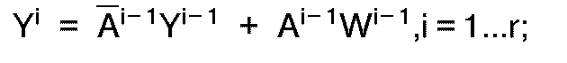
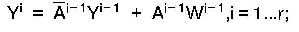
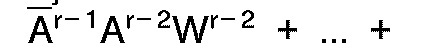
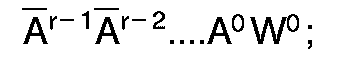
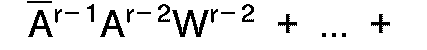
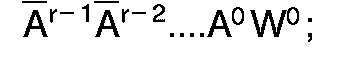
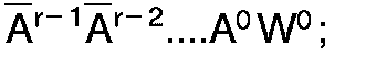
[0024] The combining circuit of the present invention is a plurality of serially connected multiplexor gates. Each gate has two data inputs; ie., one bit from the multibit weighting factor stored in circular memory and the output bit of the previous gate. The selected bits from the random pattern generator control the multiplexor gates thus determining whether the output of a given multiplexor gate is the weight bit or the output from the preceding multiplexor gate. This combining circuit implements a boolean function of the form
where A is the selected bit of a subtotal of r bits of the random pattern, W is the selected bit of a weighting factor associated with Zj having a total of r+1 bits, and Zj is the weighted random bit which forms one bit of the weighted random pattern.
[0025] This boolean function may be implemented using simple multiplexor hardware thus decreasing the generation time and circuit complexity. The boolean function produces one bit of the weighted random number in a single clock cycle. In addition, since any probability is obtainable, with any desired degree of precision, fewer test patterns will need to be generated while simultaneously providing increased fault coverage. Thus, according to the present invention, virtually any probability of generating a given bit of a test pattern having a binary value of ONE can be achieved utilizing simple hardware resulting in a high precision weighted random pattern generator which provides increased fault coverage while generating a decreased number of test patterns.
[0026] The present invention sharply contrasts from the heretofore described IBM patents. Since the possible set of all weights in the IBM patents is restricted to {1/2k,1/2k-1, ...1/2, ...1-1/2k-1, 1-1/2k}, k=1, 2, 3..., ∞ it is not possible to attain many of the weights readily achievable with the present invention. For example, the weights 5/8, 3/8, 5/16, 11/16, and so on can never be achieved utilizing the circuit disclosed in the IBM patents. In addition, the multiplexors in the present invention are controlled by the bits from the random source rather than by bits from the weight register as in the IBM patents. These distinctive features contribute to both the uniform resolution of weights and the simplification of hardware.
Brief Description of the Drawings
[0027] Figure 1 is a high-level block diagram of a generic testing system including a high precision weighted random pattern generation system according to the present invention.
[0028] Figure 2 is a block diagram of a high precision weighted random pattern generation system according to the present invention.
Description of the Preferred Embodiment
[0029] The present invention now will be described more fully hereinafter with reference to the accompanying drawings, in which a preferred embodiment of the invention is shown. Like numbers refer to like elements throughout.
[0030] Referring now to Figure 1, a high level block diagram of a generic testing system including the high precision weighted random pattern generation system according to the present invention will be described. In one embodiment, a generic testing system 1 contains a controller 2, a device under test 3, an analyzer 4, a comparator 5, a memory 6, a pass/fail register 7, and a weighted random pattern generation system 8. The device under test (DUT) 3 receives test patterns, also known as test vectors, from a weighted random pattern generation system 8. The output of DUT 3 resulting from the DUT's operation on the test pattern is transmitted to the analyzer 4. The results of the test is compared by a comparator 5 with a known set of values stored in memory 6. The pass/fail register is set to pass or fail depending on whether the comparator concludes that the DUT passed or failed the test. All operations are controlled by the controller 2. In general, this arrangement, for example, can be built into a single integrated circuit, imbedded in a board-level system as part of a self-test scheme, or made an integral part of a general purpose testing system.
[0031] In general, testing of integrated circuits using weighted random pattern generation provides a weighted test pattern which is input into the circuit under test. After processing, the results of the test are analyzed to determine defects or faults in the circuit. Internal elements of a circuit often are resistant to traditional random pattern testing. As the complexity of the circuit under test increases, so does the resistance problem. Weighted random testing has been utilized to address the problem. Weighting, in general, refers to the modification of a randomly generated bit so that the probability of generating a bit having a binary value of ONE or ZERO becomes unequal, i.e. greater than or less than 50%.
[0032] Through initial analysis of the structure of the circuit under test, those resistant elements can be found and the test patterns to which those elements are resistant can be determined. In addition, analysis results in a determination of the desired probability of generating a binary value of ONE or ZERO for each bit in a test pattern necessary to target those internal elements which are resistant to random pattern testing. The present invention will generate a given bit of a test pattern within any desired probability. In other words, the weighted random pattern generation system 8 of the present invention can achieve any probability of generating a bit of a test pattern having a binary value of ONE. This results in high precision and ensures complete and accurate testing of a complex circuit while generating a minimal number of test patterns.
[0033] Referring now to Figure 2, a schematic block diagram of the weighted random pattern generation system of the present invention is shown. The weighted random pattern generation system 8 is comprised of three major components, those being a circular memory 11, a random pattern generator 12 and a combining means 13. Both the circular memory 11 and the random pattern generator 12 are connected to and provide inputs to the combining means 13. A register 14 stores the test bits produced by the combining means.
[0034] The weighted random pattern generation system 8 produces one weighted bit of the weighted test pattern during each clock cycle. Each weighted bit produced is shifted into the weighted random pattern register 14 in which the test bits are accumulated into a test pattern, also referred to as a "test vector". Since, generally speaking, the width of the test pattern, i.e. the number of bits, is unlimited, the size of register 14 varies according to the width of the test pattern.
[0035] The circular memory 11 holds a set of weighting factors referred to as Q₀, Q₁, Q₂,...Qb-2, Qb-1 where b equals the specified width in a test pattern. Each weighting factor Q has r+1 bits. Each multibit weighting factor Qj which can be referred to as (W⁰, W¹,...Wr-1, Wr)j is associated with one respective weighted bit, i.e. Zj, to be generated and stored in register 14.
[0036] During a given clock cycle, a weighting factor is selected from memory 11 and transmitted as input into the combining means 13 via weight register 16. At the same time, r of the bits from the pattern generated by the pseudorandom pattern generator 12 are selected and input into the combining means via random pattern source register 15. The bits A⁰...Ar-1 from the random pattern act as control inputs to a cascading series of r two-input multiplexors M₀...Mr-1. The bits from one of the weighting factors (W⁰,...Wr-1, Wr)j selected from memory are the data inputs to multiplexors M⁰...Mr-1. Thus, in contrast with prior art approaches, the weighting factor is combined to form the pattern rather than act as a controller or selector of bits generated from a random source which results in the weighted random pattern.
[0037] The memory 11 is circular or recirculating in nature. The number of words stored in the memory is equal to the number of bits, b, in the resulting test pattern, i.e. the width of the test pattern. Each word in memory is a multibit weighting factor having a number of bits equal to 1 plus the desired precision r, i.e. r+1, which is used to generate a given bit in the weighted test pattern. In other words, each weighting factor Qj, i.e. (W⁰, W¹,...Wr-1, Wr)j, stored in memory is associated with a particular weighted test bit Zj of the resulting weighted test pattern. The number of bits in the weighting factor is determined by how accurately one would like to weigh the bits in the test pattern, i.e. the desired precision r.
[0038] Since one weighted test bit of the weighted test pattern is generated during each clock cycle of the weighted random pattern generation system, the weighted generator must process for a number of cycles equivalent to the number of bits b in the resulting weighted test pattern. Thus, since one weighting factor is used during one clock cycle to produce one weighted test bit, a number of weighting factors equal to the number of clock cycles needed to generate the weighted test pattern, and in turn equal to the number of bits in the weighted test pattern, must be selected. Once a weighting factor Qj is selected from memory, it is circulated in such a way that it will not be used again until all bits Z for that particular test pattern have been generated.
[0039] In other words, each weighting factor Qj is only used once during the generation of a given weighted test pattern. Thus, the circular memory 11 is a memory having "first in first out" capabilities where the value stored in memory once used is then placed at the farthest address in memory and starts to recirculate through memory as each cycle occurs. At the bit level, since the weighted pattern register 14 is a shift register, the least significant bit Zb-1 of the weighted pattern is generated first. Therefore, the weighting factors in memory 11 are stored in a manner consistent with processing such that the weighting factor Qb-1 associated with the least significant bit Zb-1 of the weighted pattern register 14 is located in memory 11 at the address to be accessed first, i.e. address b-1, and the weighting factor Q₀ associated with the most significant bit Z₀ of the weighted pattern register 14 is located at address 0, the last address for the first clock cycle.
[0040] The design of random pattern generator 12 as known to persons skilled in the art and may be in the configuration of a linear feedback shift register or a cellular automata register. See for example, Gloster, Clay S. and Brglez, Franc, Boundary Scan with Built-In Self-Test, IEEE Design & Test of Computers, February 1989, pp. 36-44. A register 15, often referred to as a random pattern source register, is contained within the random pattern generator. The random pattern is stored in the register 15 prior to processing. The size of the register 15 is s, and must be equal to or greater than r, the desired precision, in order to reduce adjacent bit correlation. A number of bits r, where r is the desired precision for the bit to be generated, Z, are selected from the source register during processing as control inputs to the combining means 13. The bit locations within the source register 15 from which the bits are selected can be arbitrary in principle. However, for best results, the bits should be truly independent. This is achieved in most cases by maximizing the spacing between the selected r bits.
[0041] Once a clock cycle is complete resulting in the generated weighted random bit Zj being shifted into weighted random pattern register 14, a new clock cycle then starts, resulting in tapping r bits from the random source register 15 and in selecting the next weighting factor of length r or r+1 which as a result of circulation in memory 11 is located at address zero. The weighting factor Qj+1 is then stored in the weight register 16 and inputs to the combining means from the random source register 15 and the weight register 16 are then processed to generate the next significant bit Zj+1 of the weighted pattern register. This process continues until a number of weighted bits equal to the length, b, of the weighted test pattern have been generated. Once the weighted test pattern has been generated, a new test pattern can be produced. The same weighting factors are used for each test pattern produced for a particular circuit under test. However, bits from the pattern source register are pseudo-random and hence different in general for each test pattern produced for a given circuit under test as well as for each weighted bit with a weighted test pattern.
[0042] Since the random bits generated by a linear feedback shift register or a cellular automata register may not always have values independent of one another, the values of the bits selected may be "scrambled" in order to enhance the independence of the values within the selected bit locations. The scrambling means 17 may take a variety of permutations in conjunction with a series of parallel EXCLUSIVE-OR gates.
[0043] The combining means 13 is comprised of a set of cascading multiplexor gates M⁰...Mr-1 each having three inputs X⁰...Xr-1, W⁰...Wr-1, A⁰...Ar-1 and one output Y¹...Yr. The output Yi from one gate is connected to one of the three inputs Xi of the immediately succeeding multiplexor gate. The other two inputs Wi and Ai respectively are bits from the weighting factor stored in the weight register 16 and from the random source register 15. The weight bit Wi from the weight register and Xi tied to the output Yi from the immediately preceding multiplexor gate Mi-1, are the two data inputs to the multiplexor gate Mi. The bit from the random source register Ai acts as a control bit for the multiplexor gate Mi. In other words, the output Yi+1 of multiplexor Mi will be either the value of input Xi or input Wi depending upon whether control input Ai is binary ZERO or ONE. The one exception to this general structure is the first multiplexor gate M⁰ in the cascading series in which the two data inputs X⁰ and W⁰ are the two bits Wr and W⁰ of the weighting factor Qj, i.e. (W⁰,...Wr-1, Wr), stored in the weight register 16 and the control bit A⁰ is the bit from the random source register 15.
[0044] The weighting function performed by the combining means 13 for generating Zj generally, will now be illustrated using actual binary values where precision r=1, 2, 3. The precision r is the desired precision for the test pattern. For illustration purposes, assume that the weighting factor Qj, associated with the weighted test bit Zj, has been loaded into weight register 16.
[0045] The simplest case is a precision of 1, i.e. r=1, or a 1 bit resolution. The combining means 13 consists of only a single multiplexor, M⁰, for r=1. In M⁰, for r=1, A⁰, the control input, selects between two data inputs, X⁰ and W⁰, producing the output Y¹. For M⁰, X⁰ is tied to Wr and since r=1, X⁰ = W¹. During any observation sequence, A⁰ will be binary ZERO half the time and binary ONE the other half of the time, since A⁰ is driven by a register cell from an unbiased pseudo random source 12. Correspondingly, the output Y¹ will be
half of the time and W⁰ the other half of the time. In other words, the probability that Y¹ attains the value of 1 can be represented by the following equation:
For r=1 and thus X⁰=W⁰, a total of four sets of data input assignments to multiplexor M⁰ can be made taken from the set of binary weight {(W¹, W⁰}: (1,1) (0,0), (0,1) and (1,0)) resulting in the set of signal probabilities {0,1/2,1} at the multiplexor output Y¹.
[0046] When it is desired that the output Y¹ be guaranteed to be binary ONE, and thus Prob[Y¹ = 1] = 1, then the weighting factor chosen must be
and the weights (W¹,W⁰) equal (1,1). Thus, the output Y¹ will always be 1. On the other hand, if it is desired that the output Y¹ never be 1, i.e. Prob[Y¹ = 1] = 0, then the weighting factor chosen must be
and the weights (W¹,W⁰) equal (0,0) to insure an output of Y¹ = 0. Where a probability of 1/2 of obtaining an output Y¹ = 1 is desired, i.e. Prob[Y¹ = 1] = 1/2, the weighting factor chosen is
and the weights (W¹,W⁰) are equal (0,1). Thus, Y¹ attains a binary value of ONE half the time and a binary value of ZERO half the time.
[0047] The weighting factor
resulting in data inputs (W¹,W⁰) = (1,0) is not utilized. The reason is that Wr (in this case W¹) is only used when a guaranteed output Y¹ = 1 is desired, i.e. Prob[Y¹=1] = 1. When the probability Prob[Y¹=1] < 1, Wr weight bit has no effect on Y¹ and therefore is simply not considered for purposes of illustration. This is true regardless of the desired precision. In addition, if the situation warrants that Prob[Y=1) will never be 1, i.e. always less than 1, then an alternative embodiment for the combining means 13 can be used wherein input X⁰ to multiplexor M⁰ is tied to binary ZERO rather than Wr.
[0048] The second case to illustrate and which follows in sequence is that for a precision of r=2. A precision of 2 requires use of two multiplexors, M⁰ and M¹, in the combining means 13. The combining means now has two control inputs A⁰ and A¹ respectively for multiplexors M⁰ and M¹. The four data inputs and two data outputs are (X⁰,W⁰), (X¹,W¹) and Y¹, Y² respectively for multiplexors M⁰ and M¹ where X⁰=Wr=W² since r=2 and X¹=Y¹. During any observation sequence, A¹ will be ZERO half the time and ONE the other half of the time since A¹ is driven by a register cell from an unbiased pseudo random source 12. As a result, A¹ will select X¹ as output Y² one half of the time and the input W¹ as output Y² the other half of the time. Remembering that Equation 1 represents the probability of attaining the value 1 for output Y¹, the probability of attaining the value 1 for Y² can be represented as follows:
Equation (1) for the case of r=1,
, can be substituted into Equation (2) resulting in the expanded equation which represents Prob[Y²=1] where r=2:
For r=2 and thus
, a total of eight sets of data input assignments can be made from the set of weighting bits {W²,W⁰,W¹} stored in weight register 16. These data input assignments are represented as follows in Table 1:
Table 1
| W² | W¹ | W⁰ | Prob[Y² = 1] |
| 0 | 0 | 0 | 0 |
| 0 | 0 | 1 | 1/4 |
| 0 | 1 | 0 | 2/4 |
| 0 | 1 | 1 | 3/4 |
| 1 | 1 | 1 | 1 |
| 1 | x | x | not used with W² = 1, except for the single entry above |
[0049] It is important to remember that where r=2, the weighting bits W² and W⁰ are inputs to multiplexor M⁰ and weighting bit W¹ is an input to multiplexor M¹. The set of signal probabilities {0,1/4,2/4,3/4,1} can be generated by the output Y² of the second multiplexor M² using the weighting bits from Table 1.
[0050] As in the case where r=1, where a guaranteed output of Y² = 1 for multiplexor M¹ is desired, Prob[Y² = 1] = 1. The weighting factor chosen must be
resulting in the weighting bits (W²,W⁰,W¹) being (1,1,1) as in line 5 of Table 1. On the other hand, when a guaranteed output of Y² ≠ 1 is desired, i.e. Prob[Y² = 1] = 0 the weighting factor must be
resulting in weighting bits (W²,W⁰,W¹) = (0,0,0) as in line 1 of Table 1. The remaining probabilities for obtaining Y²=1, i.e. 0 < Prob[Y²=1] < 1 are spaced uniformly, in increments of 1/4, evaluated from 2-r for r=2.
[0051] The present invention permits uniformly decreasing the spacing between obtainable output probabilities by simply increasing the number of multiplexors and the corresponding data and control inputs, i.e. increasing the precision r. This is demonstrated in the next case where the precision is r=3. For this case, the combining means 13 is comprised of a cascading series of three multiplexors M⁰,M¹ and M². The control inputs selected from random source register 15 are A⁰, A¹ and A² for multiplexors M⁰,M¹ and M². The data inputs to the cascading series for M⁰ are (X⁰,W⁰) where
resulting in output Y¹. The data inputs to multiplexor M¹ are (X¹,W¹) where
, resulting in output Y². The data inputs to multiplexor M² are (X²,W²) where
, resulting in the output Y³. The output Y³ for the case r=3 is the weighted test bit Zj. During any observation sequence, A² will be binary ZERO one half the time and binary ONE the other half of the time since A² is driven by a register cell from an unbiased pseudo random source 12. As a result, A² will select the input X² as output Y³ one half of the time and the input W² as output Y³ the other half of the time.
[0052] As was the case for the probabilities of attaining the value of 1 for outputs Y¹ and Y², the probability of attaining the value of 1 for output Y³ can be represented by the following equation:
When Equation (2),
, is substituted into Equation (4), the intermediate expanded equation is as follows:
When Equation (1),
is substituted into Equation (5), the final expanded form for the probability of attaining a value of 1 for output Y³ is:
For the case having precision r=3 and thus
, a total of sixteen sets of data input assignments can be made from the set of weighting bits (W³,W⁰,W¹,W²) stored in weight register 16. These data input assignments are represented as follows:
Table 2
| W³ | W² | W¹ | W⁰ | Prob[Y³ = 1] |
| 0 | 0 | 0 | 0 | 0 |
| 0 | 0 | 0 | 1 | 1/8 |
| 0 | 0 | 1 | 0 | 2/8 |
| 0 | 0 | 1 | 1 | 3/8 |
| 0 | 1 | 0 | 0 | 4/8 |
| 0 | 1 | 0 | 1 | 5/8 |
| 0 | 1 | 1 | 0 | 6/8 |
| 0 | 1 | 1 | 1 | 7/8 |
| 1 | 1 | 1 | 1 | 1 |
| 1 | x | x | x | not used with W³ = 1, except for the single entry above. |
It is important to remember that where r=3, the weighting bits W³ and W⁰ are inputs to multiplexor M⁰, weighting bits W¹ is an input to multiplexor M¹ and weighting bit W² is an input to multiplexor M². The set of signal probabilities (0,1/8,2/8,3/8,4/8,5/8,6/8,7/8,1) can be generated as output Y³ of the third multiplexor M³ using the weighting bits from Table 2.
[0053] As in the cases for r=1 and r=2, where a guaranteed output of Y³=1 for multiplexor M² is desired, i.e. output Y³ is always 1, the probability of attaining a binary ONE is 1 and represented as Prob[Y³ = 1] = 1. In order to insure an output of binary ONE, the weighting factor chosen must be
resulting in the weighting bits (W³,W⁰,W¹,W²) being (1,1,1,1) as in line 9 of Table 2. On the other hand, where a guaranteed output of Y³≠1 is desired, i.e. output Y³ is never 1, the probability of attaining a binary ONE is 0 and represented as Prob[Y³=1) = 0. In order to obtain an output consistent with this probability, the weighting factor necessary to achieve Prob[Y³=1] = 0 is
resulting in weighting bits (W³,W⁰,W¹,W²) = (0,0,0,0) as in line 1 of Table 2. The remaining probabilities of attaining an output Y³=1, i.e. 0 < Prob[Y³=1) < 1 are spaced uniformly in increments of 1/8, evaluated for 2-r for r=3.
[0054] According to the present invention, the spacing between obtainable probabilities can be uniformly decreased by increasing the number of multiplexors and the corresponding input signals, i.e. increasing the precision r. The order of the weighting bits represented as W⁰, W¹, ...Wr-1, Wr correspond with ordinary binary encoding for signals in that W⁰ represents the least significant bit and Wr represents the most significant bit. This encoding simplifies the assignment of output signal probabilities, i.e. Prob(Y¹=1] where i=1,2,...r for multiplexor outputs Y¹,...,Yr-1,Yr. In other words, a weighting factor Qj= (W⁰W¹W²W³)j for r=3 has a binary value of (0001) resulting in an assignment of a signal probability of Q (numerical equivalent) * 2-r = 1/8. Similarly, the weighting factor Q = (0011) assigns a signal probability of 3/8 to the multiplexor output. Thus, any signal probability for a multiplexor output is obtainable and is represented by:
Signal probabilities, such as 3/8 and 5/8, achievable by the present invention, can never be attained using the apparatus and methods disclosed in the IBM patents. As the value of the precision r, is increased, more signal probabilities which are not attainable using the disclosures of the IBM patents can be achieved through the present invention. In general, the choice for precision r will depend upon the properties of the DUT 3. As the value of r increases, the number of weighted random patterns required to test the circuit will generally decrease.
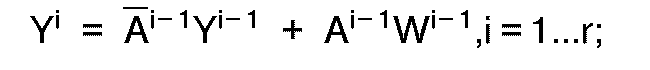
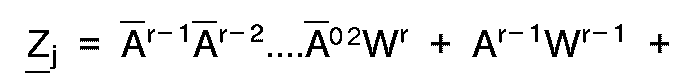
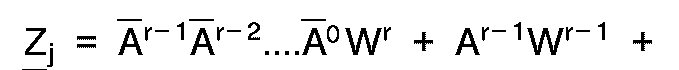
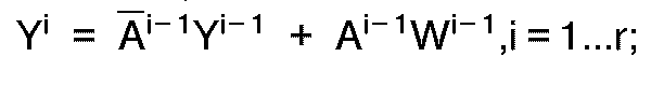
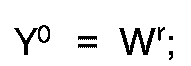
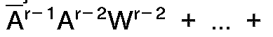
[0055] In the general case, the combining means 13, is comprised of r cascading multiplexor gates M⁰.. Mr-1, wherein r is the desired resolution. The combining means 13 combines r bits A⁰...Ar-1 from random pattern source register 15 and r+1 weighting bits W⁰...Wr from memory 11 via the weight register 16. The combining means can be represented by the boolean function:
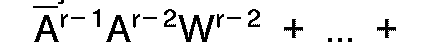
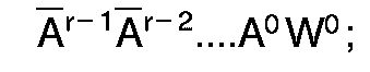
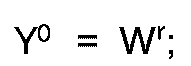
In Equation (8A), Y⁰ is equivalent X⁰. The boolean representation of the combining means 13 can be further expanded to:
Since r is the desired precision, the variables of these two boolean representations (8) and (9) relate to the hardware design in that A⁰...Ar-1 represents the r bits from the random pattern source 15; Wr represents the rth bit of the weighting factor Q which is connected to input X⁰ of the multiplexor gate of M⁰; W⁰...Wr-1 represent the remaining r bits of the weighting factor which are connected to inputs W⁰...Wr-1 of the multiplexor gates M; Y¹ represents the output from multiplexor gate M⁰; and Y²...Yr represent the remaining outputs for the remaining multiplexor gates M¹...Mr-1; and Zj represents the output Yr of multiplexor Mr-1. The output of the final multiplexor gate Mr-1 is the weighted random bit Yr, and is shifted as a bit Zj into the jth position of the weighted random pattern register 14.
[0056] The conditions under which the combining means 13 will generate weighted random patterns with a specified probability can also be represented to the rth iteration by a mathematical formula. For simplicity, set
, i.e. yi is the probability that Yi has a value of 1. If the random bits A selected from the random source register 15 are uniformly distributed, independent, random binary variables, then the P[Ai=1 Aj=1] = P[Ai-1] * P[Aj=1]. In other words, if true bit independence exists, then, the joint probability that random bit Ai has a binary value of 1 and random bit Aj has a binary value of 1 is equal to the probability that random bit Ai has a binary value of 1 multiplied by the probability that random bit Aj has a binary value of 1.
1. In a weighted random pattern generation system (8) having a memory with a plurality
of multibit weighting factors (Q) stored therein, a random pattern generator (12)
for generating a plurality of multibit random bit patterns, and means (13), connected
to said memory and said random pattern generator, for combining said multibit weighting
factors stored in said memory with said multibit random bit patterns, the system characterized
by:
said memory being a circular memory (11);
and
said combining means (13) performing said combining of said multibit weighting factors to form a mulitbit weighted random pattern in bit-sequential fashion.
said memory being a circular memory (11);
and
said combining means (13) performing said combining of said multibit weighting factors to form a mulitbit weighted random pattern in bit-sequential fashion.
2. The weighted random pattern generation system of Claim 1 wherein said combining means
comprises:
a plurality of serially connected stages (M) each having a plurality of inputs (A,X,W) and an output (Y), the output of an immediately preceding stage being connected to one (X) of said plurality of inputs of an immediately succeeding stage;
a respective bit of said multibit weighting factors (W) and a respective bit of said random bit patterns (A) being connected to the inputs of a respective one of said stages.
3. The weighted random pattern generation system of Claim 2:
wherein one of said plurality of inputs of each of said stages comprises a control input (A); and,
wherein said respective bit of said random bit pattern is connected to a respective one of said control inputs.
wherein one of said plurality of inputs of each of said stages comprises a control input (A); and,
wherein said respective bit of said random bit pattern is connected to a respective one of said control inputs.
4. The weighted random pattern generation system according to Claim 1 wherein said combining
means comprises a plurality of serially connected multiplexor gates (M), each of said
serially connected multiplexor gates having first and second data inputs (X,W), a
control input (A) and an output (Y), with the binary value of said output (Y) being
one of the binary value of said first and said second data inputs (X,W) depending
upon the binary value of said control input; the output (Y) of an immediately preceding
stage being connected to the first data input (X) of an immediately succeeding stage;
a respective bit of said multibit weighting factors being connected to a respective
one of said second data inputs (W); and a respective bit of said random bit pattern
being connected to a respective one of said control inputs (A).
5. The weighted random pattern generation system according to Claim 1 wherein said combining
means (13) combines said multibit weighting factors and said random bit pattern according
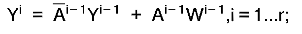
to the following boolean function:

where r is the desired precision, Ai is one bit of said random pattern, Wi is one bit of the selected one of said weighting factors, Yi is the result of combining Ai and Wi except for Y⁰ which is set to Wr, and Yr is the result of the final iteration for generating one bit of said weighted random pattern.
where r is the desired precision, Ai is one bit of said random pattern, Wi is one bit of the selected one of said weighting factors, Yi is the result of combining Ai and Wi except for Y⁰ which is set to Wr, and Yr is the result of the final iteration for generating one bit of said weighted random pattern.
6. The weighted random pattern generation system according to Claim 1 wherein said combining
means (13) combines said multibit weighting factors and said random bit pattern according
to the following boolean function:

where r is the desired precision, Ai is a bit of said random pattern, Wi is one bit of the selected one of said weighting factors and Zj is the generated weighted random bit.
where r is the desired precision, Ai is a bit of said random pattern, Wi is one bit of the selected one of said weighting factors and Zj is the generated weighted random bit.
7. The weighted random pattern generation system of Claim 1 further comprising:
a complex digital logic circuit to be tested (3);
said weighted random pattern generation system being fabricated on a single integrated circuit chip for performing boundary scan testing of said digital logic circuits.
a complex digital logic circuit to be tested (3);
said weighted random pattern generation system being fabricated on a single integrated circuit chip for performing boundary scan testing of said digital logic circuits.
8. The weighted random pattern generation system of Claim 1 wherein said random bit pattern
controls the combining of said multibit weighting factors in said combining means.
9. The weighted random pattern generation system of Claim 1 wherein combining means combines
one of said multibit weighting factors with said random bit pattern in a single clock
cycle.
10. The weighted random pattern generation system of Claim 1 further comprising:
a register (14) connected to said combining means for storing therein said weighted random pattern formed by said combining means.
a register (14) connected to said combining means for storing therein said weighted random pattern formed by said combining means.
11. The weighted random pattern generation system of Claim 1 wherein said random pattern
generator includes a register (17) for storing said random bit pattern therein, said
register being connected to said combining means.
12. The weighted random pattern generation system of Claim 1 wherein said random pattern
generator comprises a linear feedback shift register.
13. The weighted random pattern generation system of Claim 1 wherein said random pattern
generator comprises a cellular automata register.
14. The weighted random pattern generation system of Claim 1 wherein the number of bits
in said multibit weighting factors (W) are determined by the desired precision for
said weighted random pattern.
15. The weighted random pattern generation system of Claim 1 wherein each of said multibit
weighting factors (W) comprises a probability that a single bit in said weighted random
pattern equals ONE.
16. The weighted random pattern generation system of Claim 1 wherein said multibit weighting
factors comprises a probability that a single bit in said weighted random pattern
equals ZERO.
17. The weighted random pattern generation system of Claim 1 wherein bits of said random
bit pattern are independent of one another.
18. The weighted random pattern generation system of Claim 1 wherein bits of said random
bit pattern are dependent upon one another, and wherein said weighted random bit pattern
generation system further comprises scrambling means, connected between said random
bit pattern generator and said combining means, for converting the dependent portions
of said random pattern into independent portions.
19. The weighted random pattern generation system of Claim 18 wherein said scrambling
means is comprised of a plurality of EXCLUSIVE-OR gates.
20. The weighted random pattern generation system of Claim 1 in combination with a testing
system (1) for testing a device under test.
21. A weighted random pattern generation method comprising the steps of:
providing a first multibit weighting factor (W) from among a plurality of multibit weighting factors contained in a circular memory (11);
generating a first multibit random bit pattern (A);
combining the first multibit weighting factor and the first multibit random bit pattern (13) to generate a first bit of the weighted random pattern; and
repeating said providing, generating and combining steps upon second and subsequent multibit weighting factors and second and subsequent random bit patterns to generate second and subsequent bits of the weighted random pattern.
22. The weighted random pattern generation method of Claim 21 wherein said combining step
comprises the steps of:
first combining a first bit from the multibit weighting factor (W) and a first bit from the multibit random bit pattern (A) to produce a first output; and
repeating said first combining step upon second and subsequent bits from the multibit weighting factors, upon second and subsequent bits from the multibit random pattern and upon the first and subsequent outputs to produce second and subsequent outputs.
23. The weighted random pattern generation method of Claim 21 wherein said first combining
step comprises the step of:
multiplexing (M) the first bit from the multibit weighting factors (W) and a first data input (X), under control of the first bit from the multibit random bit pattern (A) to produce a first output (Y);
and wherein said repeating step comprises the step of:
multiplexing the second and subsequent bits from the multibit weighting factor (W) and the first and subsequent outputs (Y), under control of the second and subsequent bits from the multibit random bit pattern (A), to produce second and subsequent outputs.
24. The weighted random pattern generation method of Claim 21 wherein said combining step
comprises the step of:
combining said first multibit weighting factor and said first random bit pattern according to the following boolean function;
where r is the desired precision, Ai is one bit of said random pattern, Wi is one bit of the selected one of said weighting factors, Yi is the result of combining Ai and Wi except for Y⁰ which is set to Wr, and Yr is the result of the final iteration for generating one bit of said weighted random pattern.
25. The weighted random pattern generation method of Claim 21 wherein said combining step
comprises the step of:
combining said first multibit weighting factor and said first random bit pattern according to the following boolean function;


where r is the desired precision, Ai is a bit of said random pattern, Wi is one bit of the selected one of said weighting factors and Zj is the generated weighted random bit.
combining said first multibit weighting factor and said first random bit pattern according to the following boolean function;
where r is the desired precision, Ai is a bit of said random pattern, Wi is one bit of the selected one of said weighting factors and Zj is the generated weighted random bit.
26. The weighted random pattern generation method of Claim 21 wherein the generating step
comprises the step of:
generating a first multibit random bit pattern in which the bits are independent of one another.
generating a first multibit random bit pattern in which the bits are independent of one another.
27. The weighted random pattern generation method of Claim 21 wherein said generating
step comprises the steps of:
generating a first multibit random bit pattern in which the bits are dependent on one another; and
scrambling the dependent bits to provide a multibit random bit pattern in which the bits are independent of one another.
generating a first multibit random bit pattern in which the bits are dependent on one another; and
scrambling the dependent bits to provide a multibit random bit pattern in which the bits are independent of one another.
28. The weighted random pattern generation method of Claim 21 wherein the first and subsequent
bits for the random bit pattern control the combining of the first and subsequent
bits of the multibit weighting factor.
29. The weighted random pattern generation method of Claim 21 wherein said combining step
is performed in a single clock cycle.
1. System (8) zum Erzeugen eines gewichteten Zufallsmusters, mit einem Speicher, in dem
eine Vielzahl von Multibit-Gewichtungsfaktoren (Q) gespeichert ist, einem Zufallsmustergenerator
(12) zum Erzeugen einer Vielzahl von Multibit-Zufalls-Bitmustern, und einer Einrichtung
(13), die mit dem genannten Speicher und dem genannten Zufallsmustergenerator verbunden
ist, um die genannten Multibit-Gewichtungsfaktoren, die in dem genannten Speicher
gespeichert sind, mit den genannten Multibit-Zufalls-Bitmustern zu kombinieren,
gekennzeichnet durch:
der genannte Speicher ist ein Ringspeicher (11); und
die genannte Kombinationseinrichtung (13) führt die genannte Kombination der genannten Multibit-Gewichtungsfaktoren zur Bildung eines gewichteten Multibit-Zufallsmusters nach Art einer Bitfolge durch.
gekennzeichnet durch:
der genannte Speicher ist ein Ringspeicher (11); und
die genannte Kombinationseinrichtung (13) führt die genannte Kombination der genannten Multibit-Gewichtungsfaktoren zur Bildung eines gewichteten Multibit-Zufallsmusters nach Art einer Bitfolge durch.
2. System zum Erzeugen eines gewichteten Zufallsmusters nach Anspruch 1, worin die genannte
Kombinationseinrichtung die folgenden Merkmale aufweist:
eine Anzahl in Reihe angeschlossener Stufen (M), von denen jede eine Vielzahl von Eingängen (A, X, W) und einen Ausgang (Y) aufweist, wobei der Ausgang einer unmittelbar vorangehenden Stufe mit einem (X) der Vielzahl von Eingängen einer unmittelbar nachfolgenden Stufe verbunden ist;
ein jeweiliges Bit der genannten Multibit-Gewichtungsfaktoren (W) und ein jeweiliges Bit der genannten Zufalls-Bitmuster (A) werden an die Eingänge einer jeweiligen der genannten Stufen angeschlossen.
3. System zum Erzeugen eines gewichteten Zufallsmusters nach Anspruch 2:
worin eine der genannten Vielzahl von Eingängen einer jeden der genannten Stufen einen Steuereingang (A) aufweist; und
worin das genannte jeweilige Bit des genannten Zufalls-Bitmusters mit einem jeweiligen der genannten Steuereingänge verbunden ist.
worin eine der genannten Vielzahl von Eingängen einer jeden der genannten Stufen einen Steuereingang (A) aufweist; und
worin das genannte jeweilige Bit des genannten Zufalls-Bitmusters mit einem jeweiligen der genannten Steuereingänge verbunden ist.
4. System zum Erzeugen eines gewichteten Zufallsmusters nach Anspruch 1, worin die genannte
Kombinationseinrichtung eine Vielzahl von in Reihe angeschlossener multiplexer Gatter
(M) aufweist, jedes der genannten, in Reihe angeschlossener multiplexer Gatter einen
ersten und zweiten Dateneingang (X, W), einen Steuereingang (A) und einen Ausgang
(Y) aufweist, wobei der binäre Wert des genannten Ausganges (Y) einer des binären
Werts des genannten ersten und des genannten zweiten Dateneingangs (X, W) in Abhängigkeit
vom binären Wert des genannten Steuereingangs ist; der Ausgang (Y) einer unmittelbar
vorangehenden Stufe mit dem ersten Dateneingang (X) einer unmittelbar nachfolgenden
Stufe verbunden ist; ein jeweiliges Bit der genannten Multibit-Gewichtungsfaktoren
an jeweils einen der genannten zweiten Dateneingänge (W) angeschlossen ist; und ein
jeweiliges Bit des genannten Zufalls-Bitmusters mit einem jeweiligen der genannten
Steuereingänge (A) verbunden ist.
5. System zum Erzeugen eines gewichteten Zufallsmusters nach Anspruch 1, worin die genannte
Kombinationseinrichtung (13) die genannten Multibit-Gewichtungsfaktoren und das genannte
Zufalls-Bitmuster entsprechend der folgenden Boole'schen Funktion kombiniert:

wobei r die gewünschte Genauigkeit ist, Ai ein Bit des genannten Zufallsmustes ist, Wi ein Bit des ausgewählten der genannten Gewichtungsfaktoren ist, Yi das Ergebnis der Kombination von Ai und Wi ist, ausgenommen Y⁰, das eingesetzt wird für Wr, und Yr das Ergebnis der abschließenden Interation zum Erzeugen eines Bits des genannten gewichteten Zufallsmusters ist.
wobei r die gewünschte Genauigkeit ist, Ai ein Bit des genannten Zufallsmustes ist, Wi ein Bit des ausgewählten der genannten Gewichtungsfaktoren ist, Yi das Ergebnis der Kombination von Ai und Wi ist, ausgenommen Y⁰, das eingesetzt wird für Wr, und Yr das Ergebnis der abschließenden Interation zum Erzeugen eines Bits des genannten gewichteten Zufallsmusters ist.
6. System zum Erzeugen eines gewichteten Zufallsmusters nach Anspruch 1, worin die genannte
Kombinationseinrichtung (13) die genannten Multibit-Gewichtungsfaktoren und die genannten
Zufalls-Bitmuster entsprechend der folgenden Boole'schen Funktion kombiniert:
wobei r die gewünschte Genauigkeit ist, Ai ein Bit des genannten Zufallsmusters ist, Wi ein Bit eines ausgewählten der genannten Gewichtungsfaktoren ist und Zj das erzeugte gewichtete Zufalls-Bit ist.
wobei r die gewünschte Genauigkeit ist, Ai ein Bit des genannten Zufallsmusters ist, Wi ein Bit eines ausgewählten der genannten Gewichtungsfaktoren ist und Zj das erzeugte gewichtete Zufalls-Bit ist.
7. System zum Erzeugen eines gewichteten Zufallsmusters nach Anspruch 1, ferner mit:
einer komplexen digitalen logischen Schaltung, die zu testen ist (3);
das genannte System zum Erzeugen eines gewichteten Zufallsmusters ist auf einem einzigen Chip mit einer integrierten Schaltung hergestellt, um eine Grenzabtastungsüberprüfung der genannten digitalen logischen Schaltungen durchzuführen.
8. System zum Erzeugen eines gewichteten Zufallsmusters nach Anspruch 1, worin das genannte
Zufalls-Bitmuster die Kombination der genannten Multibit-Gewichtungsfaktoren in der
genannten Kombinationseinrichtung steuert.
9. System zum Erzeugen eines gewichteten Zufallsmusters nach Anspruch 1, worin die Kombinationseinrichtung
einen der genannten Multibit-Gewichtungsfaktoren mit dem genannten Zufalls-Bitmuster
in einem einzigen Taktzyklus kombiniert.
10. System zum Erzeugen eines gewichteten Zufallsmusters nach Anspruch 1, ferner mit:
einem Register (14), das an die genannte Kombinationseinrichtung angeschlossen ist, um hierin das gewichtete Zufallsmuster zu speichern, das von der genannten Kombinationseinrichtung gebildet ist.
einem Register (14), das an die genannte Kombinationseinrichtung angeschlossen ist, um hierin das gewichtete Zufallsmuster zu speichern, das von der genannten Kombinationseinrichtung gebildet ist.
11. System zum Erzeugen eines gewichteten Zufallsmusters nach Anspruch 1, worin der genannte
Zufallsmustergenerator ein Register (17) umfaßt, um hierin das genannte Zufalls-Bitmuster
zu speichern, wobei das genannte Register an die genannte Kombinationseinrichtung
angeschlossen ist.
12. System zum Erzeugen eines gewichteten Zufallsmusters nach Anspruch 1, worin der genannte
Zufallsmustergenerator ein lineares Rückkopplungs-Schieberegister aufweist.
13. System zum Erzeugen eines gewichteten Zufallsmusters nach Anspruch 1, worin der genannte
Zufallsmustergenerator ein Zellular-Automatenregister aufweist.
14. System zum Erzeugen eines gewichteten Zufallsmusters nach Anspruch 1, worin die Anzahl
von Bits in den genannten Multibit-Gewichtungsfaktoren (W) bestimmt wird durch die
gewünschte Genauigkeit für das genannte gewichtete Zufallsmuster.
15. System zum Erzeugen eines gewichteten Zufallsmusters nach Anspruch 1, worin jeder
der genannten Multibit-Gewichtungsfaktoren (W) eine Wahrscheinlichkeit aufweist, daß
ein Einzelbit im genannten gewichteten Zufallsmuster EINS gleich ist.
16. System zum Erzeugen eines gewichteten Zufallsmusters nach Anspruch 1, worin der genannte
Multibit-Gewichtungsfaktor eine Wahrscheinlichkeit aufweist, daß ein Einzelbit im
genannten gewichteten Zufallsmuster NULL gleich ist.
17. System zum Erzeugen eines gewichteten Zufallsmusters nach Anspruch 1, worin Bits des
genannten Zufalls-Bitmusters voneinander unabhängig sind.
18. System zum Erzeugen eines gewichteten Zufallsmusters nach Anspruch 1, worin Bits des
genannten Zufalls-Bitmusters voneinander abhängig sind, und worin das genannte System
zum Erzeugen eines gewichteten Zufallsmusters ferner eine Verwürfelungseinrichtung
aufweist, die zwischen dem genannten Zufalls-Bitmuster-Generator und der genannten
Kombinationseinrichtung angeschlossen ist, um die abhängigen Abschnitte des genannten
Zufallsmusters in unabhängige Abschnitte umzuwandeln.
19. System zum Erzeugen eines gewichteten Zufallsmusters nach Anspruch 18, worin jede
Verwürfelungseinrichtung zusammengesetzt ist aus einer Vielzahl von Antivalenz-Gattern.
20. System zum Erzeugen eines gewichteten Zufallsmusters nach Anspruch 1 in Kombination
mit einem PrüfSystem (1) zum Prüfen einer im Prüfversuch befindlichen Vorrichtung.
21. System zum Erzeugen eines gewichteten Zufallsmusters, mit den folgenden Schritten:
Bereitstellen eines ersten Multibit-Gewichtungsfaktors (W) aus einer Vielzahl von Multibit-Gewichtungsfaktoren heraus, die in einem Ringspeicher (11) enthalten sind;
Erzeugen eines ersten Multibit-Zufalls-Bitmusters (A);
Kombinieren des ersten Multibit-Gewichtungsfaktors und des ersten Multibit-Zufalls-Bitmusters (13), um ein erstes Bit des gewichteten Zufallsmusters zu erzeugen; und
Wiederholen der genannten Schritte des Bereitstellens, Erzeugens und Kombinierens auf der Grundlage zweiter und nachfolgender Multibit-Gewichtungsfaktoren sowie zweiter und nachfolgender Zufalls-Bitmuster, um zweite und nachfolgende Bits des gewichteten Zufallsmusters zu erzeugen.
22. System zum Erzeugen eines gewichteten Zufallsmusters nach Anspruch 21, worin der genannte
Kombinationsschritt die folgenden Schritte aufweist:
ein erstes Kombinieren eines ersten Bits aus dem Multibit-Gewichtungsfaktor (W) mit einem ersten Bit aus dem Multibit-Zufalls-Bitmuster (A), um eine erste Ausgabe zu erzeugen; und
Wiederholen des ersten Kombinationsschrittes auf der Grundlage eines zweiten und nachfolgender Bits aus den Multibit-Gewichtungsfaktoren, auf der Grundlage eines zweiten und nachfolgender Bits aus dem Multibit-Zufallsmuster und auf der Grundlage einer ersten und nachfolgenden Ausgabe, um zweite und nachfolgende Ausgaben zu erzeugen.
23. System zum Erzeugen eines gewichteten Zufallsmusters nach Anspruch 21, worin der erste
Kombinationsschritt den folgenden Schritt aufweist:
Multiplexen (M) des ersten Bits aus den Multibit-Gewichtungsfaktoren (W) und einer ersten Dateneingabe (X) unter Steuerung des ersten Bits aus dem Multibit-Zufalls-Bitmuster (A), um eine erste Ausgabe (Y) zu erzeugen;
und worin der genannte Wiederholungsschritt den folgenden Schritt aufweist:
Multiplexen des zweiten und nachfolgenden Bits aus den Multibit-Gewichtungsfaktoren (W) und den ersten und nachfolgenden Ausgaben (Y) unter Steuerung des zweiten und nachfolgenden Bits aus dem Multibit-Zufalls-Bitmuster (A), um eine zweite und nachfolgende Ausgaben zu erzeugen.
24. System zum Erzeugen eines gewichteten Zufallsmusters nach Anspruch 21, worin der genannte
Kombinationsschritt den folgenden Schritt aufweist:
Kombinieren des genannten ersten Multibit-Gewichtungsfaktors des genannten ersten Zufalls-Bitmusters entsprechend der folgenden Boole'schen Funktion:

wobei r die gewünschte Genauigkeit ist, Ai ein Bit des genannten Zufallsmusters ist, Wi ein Bit des ausgewählten der genannten Gewichtungsfaktoren ist, Yi das Ergebnis der Kombination von Ai und Wi ist, ausgenommen Y⁰, das eingesetzt wird für Wr, und Yr das Ergebnis der abschließenden Iteration zum Erzeugen eines Bits des genannten gewichteten Zufallsmusters ist.
Kombinieren des genannten ersten Multibit-Gewichtungsfaktors des genannten ersten Zufalls-Bitmusters entsprechend der folgenden Boole'schen Funktion:
wobei r die gewünschte Genauigkeit ist, Ai ein Bit des genannten Zufallsmusters ist, Wi ein Bit des ausgewählten der genannten Gewichtungsfaktoren ist, Yi das Ergebnis der Kombination von Ai und Wi ist, ausgenommen Y⁰, das eingesetzt wird für Wr, und Yr das Ergebnis der abschließenden Iteration zum Erzeugen eines Bits des genannten gewichteten Zufallsmusters ist.
25. System zum Erzeugen eines gewichteten Zufallsmusters nach Anspruch 21, worin der genannte
Kombinationsschritt den folgenden Schritt aufweit:
Kombinieren des ersten Multibit-Gewichtungsfaktors mit dem ersten Zufalls-Bitmuster entsprechend der nachfolgenden Boole'schen Funktion:

wobei r die gewünschte Genauigkeit ist, Ai ein Bit des genannten Zufallsmusters ist, Wi ein Bit des ausgewählten der genannten Gewichtungsfaktoren ist und Zj das erzeugte, gewichtete Zufallsmuster ist.
Kombinieren des ersten Multibit-Gewichtungsfaktors mit dem ersten Zufalls-Bitmuster entsprechend der nachfolgenden Boole'schen Funktion:
wobei r die gewünschte Genauigkeit ist, Ai ein Bit des genannten Zufallsmusters ist, Wi ein Bit des ausgewählten der genannten Gewichtungsfaktoren ist und Zj das erzeugte, gewichtete Zufallsmuster ist.
26. System zum Erzeugen eines gewichteten Zufallsmusters nach Anspruch 21, worin der Erzeugungsschritt
den folgenden Schritt aufweist:
Erzeugen eines ersten Multibit-Zufalls-Bitmusters, worin die Bits voneinander unabhängig sind.
Erzeugen eines ersten Multibit-Zufalls-Bitmusters, worin die Bits voneinander unabhängig sind.
27. System zum Erzeugen eines gewichteten Zufallsmusters nach Anspruch 21, worin der genannte
Erzeugungsschritt die folgenden Schritte aufweist:
Erzeugen eines ersten Multibit-Zufalls-Bitmusters, worin die Bits voneinander abhängig sind; und
Verwürfeln der abhängigen Bits, um ein Multibit-Zufalls-Bitmuster vorzusehen, worin die Bits voneinander unabhängig sind.
Erzeugen eines ersten Multibit-Zufalls-Bitmusters, worin die Bits voneinander abhängig sind; und
Verwürfeln der abhängigen Bits, um ein Multibit-Zufalls-Bitmuster vorzusehen, worin die Bits voneinander unabhängig sind.
28. System zum Erzeugen eines gewichteten Zufallsmusters nach Anspruch 21, worin das erste
und nachfolgende Bits für das Zufalls-Bitmuster die Kombination des ersten und nachfolgenden
Bits des Multibit-Gewichtungsfaktors steuern.
29. System zum Erzeugen eines gewichteten Zufallsmusters nach Ansrpuch 21, worin der genannte
Kombinationsschritt in einem einzigen Taktzyklus durchgeführt wird.
1. Dans un système de génération de configuration aléatoire pondérée (8) comprenant une
mémoire dans laquelle est stockée une pluralité de facteurs de pondération multibits
(Q), un générateur de configuration aléatoire (12) pour engendrer une pluralité de
configurations ou combinaisons binaires aléatoires multibits, et des moyens (13) connectés
à ladite mémoire et audit générateur de configuration aléatoire pour combiner lesdits
facteurs de pondération multibits stockés dans ladite mémoire avec les dites configurations
binaires aléatoires multibits, le système étant caractérisé en ce que :
ladite mémoire est une mémoire circulaire (11); et
lesdits moyens de combinaison (13) exécutent la dite combinaison desdits facteurs de pondération multibits pour former une configuration aléatoire pondérée multibit, de façon séquentielle par bit.
ladite mémoire est une mémoire circulaire (11); et
lesdits moyens de combinaison (13) exécutent la dite combinaison desdits facteurs de pondération multibits pour former une configuration aléatoire pondérée multibit, de façon séquentielle par bit.
2. Système de génération de configuration aléatoire pondérée suivant la revendication
1, dans lequel lesdits moyens de combinaison comprennent :
une pluralité d'étages connectés en série (M) ayant chacun une pluralité d'entrées (A,X,W) et une sortie (Y), la sortie d'un étage immédiatement précédent étant connectée à une (X) de ladite pluralité d'entrées d'un étage immédiatement suivant ; et
un bit respectif desdits facteurs de pondération multibits (W) et un bit respectif desdites configurations binaires aléatoires (A) sont connectés aux entrées d'un étage respectif desdits étages.
3. Système de génération de configuration aléatoire pondérée suivant la revendication
2, dans lequel:
une de ladite pluralité d'entrées de chacun des dits étages est une entrée de commande (A) ; et
ledit bit respectif de ladite configuration binaire aléatoire est connecté à une entrée respective des dites entrées de commande.
une de ladite pluralité d'entrées de chacun des dits étages est une entrée de commande (A) ; et
ledit bit respectif de ladite configuration binaire aléatoire est connecté à une entrée respective des dites entrées de commande.
4. Système de génération de configuration aléatoire pondérée suivant la revendication
1, dans lequel lesdits moyens de combinaison comprennent une pluralité de portes de
multiplexeur connectées en série (M), chacune desdites portes de multiplexeur connectées
en série ayant une première et une deuxième entrées de données (X,W), une entrée de
commande (A) et une sortie (Y), la valeur binaire de ladite sortie (Y) étant une des
valeurs binaires des dites première et deuxième entrées de données (X,W) en fonction
de la valeur binaire de ladite entrée de commande ; la sortie (Y) d'un étage immédiatement
précédent étant connectée à la première entrée de données (X) d'un étage immédiatement
suivant ; un bit respectif desdits facteurs de pondération multibits étant connecté
à une entrée respective desdites deuxièmes entrées de données (W) ; et un bit respectif
de ladite configuration binaire aléatoire étant connecté à une entrée respective desdites
entrées de commande (A).
5. Système de génération de configuration aléatoire pondérée suivant la revendication
1, dans lequel lesdites moyens de combinaison (13) combinent lesdits facteurs de pondération
multibits et ladite configuration binaire aléatoire conformément à la fonction booléenne
suivante :
dans laquelle r est la précision désirée, Ai est un bit de ladite configuration aléatoire ; Wi est un bit du facteur choisi parmi lesdits facteurs de pondération , Yi est le résultat de la combinaison de Aiet de Wi sauf pour Y⁰ qui est établi à Wr, et Yr est le résultat de l'itération finale pour engendrer un bit de ladite configuration aléatoire pondérée.
dans laquelle r est la précision désirée, Ai est un bit de ladite configuration aléatoire ; Wi est un bit du facteur choisi parmi lesdits facteurs de pondération , Yi est le résultat de la combinaison de Aiet de Wi sauf pour Y⁰ qui est établi à Wr, et Yr est le résultat de l'itération finale pour engendrer un bit de ladite configuration aléatoire pondérée.
6. Système de génération de configuration aléatoire pondérée suivant la revendication
1, dans lequel lesdits moyens de combinaison (13) combinent lesdits facteurs de pondération
multibits et ladite configuration binaire aléatoire conformément à la fonction booléenne
suivante :

dans laquelle r est la précision désirée, Ai est un bit de ladite configuration aléatoire, Wi est un bit du facteur choisi parmi lesdits facteurs de pondération et Zj est le bit engendré de la configuration aléatoire pondérée.
dans laquelle r est la précision désirée, Ai est un bit de ladite configuration aléatoire, Wi est un bit du facteur choisi parmi lesdits facteurs de pondération et Zj est le bit engendré de la configuration aléatoire pondérée.
7. Système de génération de configuration aléatoire pondérée suivant la revendication
1, comprenant en outre :
un circuit logique numérique complexe à vérifier (3) ;
ledit système de génération de configuration aléatoire pondérée étant fabriqué sur une puce de circuit intégré unique pour effectuer une vérification par balayage des limites desdits circuits logiques numériques.
un circuit logique numérique complexe à vérifier (3) ;
ledit système de génération de configuration aléatoire pondérée étant fabriqué sur une puce de circuit intégré unique pour effectuer une vérification par balayage des limites desdits circuits logiques numériques.
8. Système de génération de configuration aléatoire pondérée suivant la revendication
1, dans lequel ladite configuration binaire aléatoire commande la combinaison desdits
facteurs de pondération multibits dans les dits moyens de combinaison.
9. Système de génération de configuration aléatoire pondérée suivant la revendication
1, dans lequel les moyens de combinaison combinent un desdits facteurs de pondération
multibits avec ladite configuration binaire aléatoire en un seul cycle d'horloge.
10. Système de génération de configuration aléatoire pondérée suivant la revendication
1, comprenant en outre :
un registre (14) connecté auxdits moyens de combinaison, pour stocker dans ce registre ladite configuration aléatoire pondérée formée par lesdits moyens de combinaison.
un registre (14) connecté auxdits moyens de combinaison, pour stocker dans ce registre ladite configuration aléatoire pondérée formée par lesdits moyens de combinaison.
11. Système de génération de configuration aléatoire pondérée suivant la revendication
1 , dans lequel ledit générateur de configuration aléatoire comprend un registre (17)
pour le stockage de ladite configuration binaire aléatoire, ledit registre étant connecté
auxdits moyens de combinaison.
12. Système de génération de configuration aléatoire pondérée suivant la revendication
1, dans lequel ledit générateur de configuration aléatoire comprend un registre à
décalage à réaction linéaire.
13. Système de génération de configuration aléatoire pondérée suivant la revendication
1, dans lequel ledit générateur de configuration aléatoire comprend un registre à
automate cellulaire.
14. Système de génération de configuration aléatoire pondérée suivant la revendication
1, dans lequel le nombre de bits dans lesdits facteurs de pondération multibits (W)
est déterminé par la précision désirée pour ladite configuration aléatoire pondérée.
15. Système de génération de configuration aléatoire pondérée suivant la revendication
1, dans lequel chacun desdits facteurs de pondération multibits (W) possède une probabilité
qu'un seul bit dans ladite configuration aléatoire pondérée soit égal à UN.
16. Système de génération de configuration aléatoire pondérée suivant la revendication
1, dans lequel lesdits facteurs de pondération multibits possèdent une probabilité
qu'un seul bit de ladite configuration aléatoire pondérée soit égal à ZERO.
17. Système de génération de configuration aléatoire pondérée suivant la revendication
1, dans lequel les bits de ladite configuration binaire aléatoire sont indépendants
les uns des autres.
18. Système de génération de configuration aléatoire pondérée suivant la revendication
1, dans lequel les bits de ladite configuration binaire aléatoire dépendent les uns
des autres,et dans lequel ledit système de génération de configuration binaire aléatoire
pondérée comprend en outre des moyens de brouillage, connectés entre ledit générateur
de configuration binaire aléatoire et lesdits moyens de combinaison, pour convertir
les parties dépendantes de ladite configuration aléatoire en parties indépendantes.
19. Système de génération de configuration aléatoire pondérée suivant la revendication
18, dans lequel lesdits moyens de brouillage sont composés d'une pluralité de portes
OU-EXCLUSIF.
20. Système de génération de configuration aléatoire pondérée suivant la revendication
1, en combinaison avec un système de vérification (1) pour vérifier un dispositif
en examen.
21. Méthode de génération de configuration aléatoire pondérée, comprenant les étapes de
:
choix d'un premier facteur de pondération multibits (W) parmi une pluralité de facteurs de pondération multibits contenus dans une mémoire circulaire (11) ;
génération d'une première configuration binaire aléatoire multibit (A) ;
combinaison du premier facteur de pondération multibit et de la première configuration binaire aléatoire multibit (13), pour produire un premier bit de la configuration aléatoire pondérée ; et
répétition desdites étapes de choix, de génération et de combinaison sur le deuxième facteur et les facteurs suivants de pondération multibits et sur la deuxième configuration et les configurations binaires aléatoires suivantes, pour engendrer un deuxième bit et des bits suivants de la configuration aléatoire pondérée.
22. Méthode de génération de configuration aléatoire pondérée suivant la revendication
21, dans laquelle ladite étape de combinaison comprend les étapes de:
combinaison initiale d'un premier bit du facteur de pondération multibit (W) et d'un premier bit de la configuration binaire aléatoire multibit (A), pour produire une première sortie ; et
répétition de ladite étape de combinaison initiale sur le deuxième bit et les bits suivants des facteurs de pondération multibits, sur le deuxième bit et les bits suivants de la configuration aléatoire multibit et sur la première sortie et les sorties suivantes, pour produire une deuxième sortie et des sorties suivantes.
23. Méthode de génération de configuration aléatoire pondérée suivant la revendication
21, dans laquelle l'étape de combinaison initiale comprend l'étape de:
multiplexage (M) du premier bit des facteurs de pondération multibits (W) et d'une première entrée de données (X), sous la commande du premier bit de la configuration binaire aléatoire multibit (A), pour produire une première sortie (Y) ;
et dans laquelle ladite étape de répétition comprend l'étape de :
multiplexage du deuxième bit et des bits suivants du facteur de pondération multibit (W) et de la première sortie et des sorties suivantes (Y), sous la commande du deuxième bit et des bits suivants de la configuration binaire aléatoire multibit (A), pour produire une deuxième sortie et des sorties suivantes.
24. Méthode de génération de configuration aléatoire pondérée suivant la revendication
21, dans laquelle ladite étape de combinaison comprend l'étape de :
combinaison dudit premier facteur de pondération multibit et de ladite première configuration binaire aléatoire conformément à la fonction booléenne suivante :
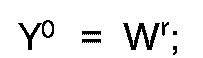
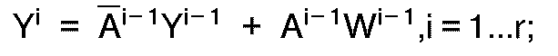
dans laquelle r est la précision désirée, Ai est un bit de ladite configuration aléatoire, Wi est un bit du facteur choisi parmi lesdits facteurs de pondération, Yi est le résultat de la combinaison de Ai et Wi sauf pour Y⁰ qui est établi à Wr, et Yr est le résultat de l'itération finale pour produire un bit de ladite configuration aléatoire pondérée.
combinaison dudit premier facteur de pondération multibit et de ladite première configuration binaire aléatoire conformément à la fonction booléenne suivante :
dans laquelle r est la précision désirée, Ai est un bit de ladite configuration aléatoire, Wi est un bit du facteur choisi parmi lesdits facteurs de pondération, Yi est le résultat de la combinaison de Ai et Wi sauf pour Y⁰ qui est établi à Wr, et Yr est le résultat de l'itération finale pour produire un bit de ladite configuration aléatoire pondérée.
25. Méthode de génération de configuration aléatoire pondérée suivant la revendication
21, dans laquelle ladite étape de combinaison comprend l'étape de :
combinaison dudit premier facteur de pondération multibit et de ladite première configuration binaire aléatoire conformément à la fonction booléenne suivante :
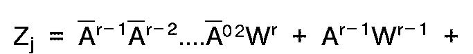
dans laquelle r est la précision désirée, Ai est un bit de ladite configuration aléatoire, Wi est un bit du facteur choisi parmi lesdits facteurs de pondération, et Zj est le bit engendré de la configuration aléatoire pondérée.
combinaison dudit premier facteur de pondération multibit et de ladite première configuration binaire aléatoire conformément à la fonction booléenne suivante :
dans laquelle r est la précision désirée, Ai est un bit de ladite configuration aléatoire, Wi est un bit du facteur choisi parmi lesdits facteurs de pondération, et Zj est le bit engendré de la configuration aléatoire pondérée.
26. Méthode de génération de configuration aléatoire pondérée suivant la revendication
21, dans laquelle l'étape de génération comprend l'étape de :
génération d'une première configuration binaire aléatoire multibit dans laquelle les bits sont indépendants les uns des autres.
génération d'une première configuration binaire aléatoire multibit dans laquelle les bits sont indépendants les uns des autres.
27. Méthode de génération de configuration aléatoire pondérée suivant la revendication
21, dans laquelle ladite étape de génération comprend les étapes de :
génération d'une première configuration binaire aléatoire multibit dans laquelle les bits dépendent les uns des autres ; et
brouillage des bits dépendants, pour produire une configuration binaire aléatoire multibit dans laquelle les bits sont indépendants les uns des autres.
génération d'une première configuration binaire aléatoire multibit dans laquelle les bits dépendent les uns des autres ; et
brouillage des bits dépendants, pour produire une configuration binaire aléatoire multibit dans laquelle les bits sont indépendants les uns des autres.
28. Méthode de génération de configuration aléatoire pondérée suivant la revendication
21, dans laquelle le premier bit et les bits suivants pour la configuration binaire
aléatoire commandent la combinaison du premier bit et des bits suivants du facteur
de pondération multibit.
29. Méthode de génération de configuration aléatoire pondérée suivant la revendication
21, dans laquelle ladite étape de combinaison est effectuée en un seul cycle d'horloge.