| (19) |
 |
|
(11) |
EP 0 614 716 A1 |
| (12) |
EUROPEAN PATENT APPLICATION |
| (43) |
Date of publication: |
|
14.09.1994 Bulletin 1994/37 |
| (22) |
Date of filing: 24.01.1994 |
|
| (51) |
International Patent Classification (IPC)5: B23B 31/40 |
|
| (84) |
Designated Contracting States: |
|
CH DE FR GB IT LI |
| (30) |
Priority: |
08.02.1993 CN 93227250
|
| (71) |
Applicant: Xu, Xian Hua |
|
Shenyang City (CN) |
|
| (72) |
Inventor: |
|
- Xu, Xian Hua
Shenyang City (CN)
|
| (74) |
Representative: Goddar, Heinz J., Dr. |
|
FORRESTER & BOEHMERT
Franz-Joseph-Strasse 38
80801 München
80801 München (DE) |
|
| |
|
| (54) |
Mandrel for processing workpiece with internal spline |
(57) This is a kind of mandrel for processing workpiece with internal spline. Its technical
characteristics are that two half-keys separated by a lever are installed in lower
grooves of a cylindrical and elastic clack clip (8). The lever (10) has a conical
head in the lower end within the cylinder, and an expanding sleeve (9), a spring (7),
steel bells (6), a sleeve (5), steel balls (4), an upper sleeve (3), steel balls (2)
and a nut (1) are assembled in order. This new and practical mandrel is used in processing
workpiece with internal spline in high precision and efficiency.
|
|
[0001] This new and practical tool is a kind of parts of machine tool especially a mandrel
used for internal spline.
[0002] General technology, such as Chinese Patent CN88216959.9 "Internal Spline Side Grinder",
uses a mandrel which fixed to a rotary working table by a lower conical handle to
clamp the workpiece with an elastic clack clip. This method cann't reach high positioning
precision because only the upper section of a clack clip contacts with workpiece.
Also, it is a trouble pre-positioning work with low efficiency that the lower section
is fixed by a conical handle without a positioning unit.
[0003] The new and practical mandrel has been engineered for processing workpiece which
has internal spline with high precision and efficiency.
[0004] How to reach this purpose: two half-keys separated by a lever are installed in the
lower groove of a cylindrical and elastic clack clip; there is a lever which has a
conical head in the lower end within the cylinder, and an expanding sleeve, a spring,
steel balls, a sleeve, steel balls, an upper sleeve, steel balls and a nut are assemblied
in order. At least a passing groove exists between two keys in the spine of a cylindrical
and elastic clack clip.
[0005] A detail explanation has been given with illustration as follows.
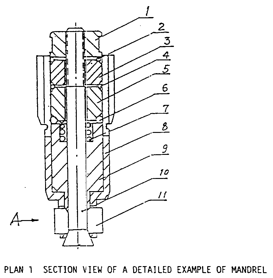
[0006] Plan 1 is section view of a detail example of mandrel.
[0007] Plan 2 is "A" view of Plan 1.
[0008] Plan 3 is vertical view of Plan 1.
[0009] Plan 4 is outline drawing of Plan 1.
[0010] Plan 5 is "B-B" section view of Plan 3.
[0011] From Plan 1 to Plan 5 two half-keys are installed in a lower and open groove of a
cylindrical and elastic clack clip 8. A lever 10 with a screwed upper end and a conical
head in the lower end is inside of the elastic clack clip. An expanding sleeve 9,
a spring 7, steel balls 6, a sleeve 5, steel balls 4, an upper sleeve 3, steel balls
2 and a nut 1 are assemblied in order. The outer face of the elastic clack clip 8
upper section is processed in a spline shape and at least a passing groove exists
between two opposite keys. The expanding sleeve 9 has a conical face in the lower
section; the outer circle of the upper sleeve 3 and the sleeve 5 has a chamfer. Steel
balls 2, 4 and 6 are separately placed into the groove formed by a nut, the upper
sleeve 3 and the outer face chamfer of the sleeve 5. In operation, put the half-keys
11 into the central bore of the rotary table and a processing workpiece into the upper
section of the elastic clack clip 8. Rotating nut 1 makes the mandrel accurately fixed
on the rotary table by steel balls, 2, 4 and 6, the upper sleeve 3, the sleeve 5,
the expanding sleeve 9 and the conical head of the lever 10 to force the clack clip
11 open together. With the nut rotating continuously, the chamfer of the upper sleeve
3 and the sleeve 5 push the steel balls 2, 4 and 6 to force the elastic clack clip
8 open for fixing the workpiece. Rotating the nut in reversing direction, the workpiece
and mandrel are taken down. It is convenient to fix and take down the workpiece in
short time and high precision by using this new and practical mandrel. A high efficiency
of production can be got in processing workpiece with internal spline.
1. A kind of mandrel is comprised of an elastic clack clip for processing workpiece with
internal spline. It characterizes that two half-keys separated by a lever are installed
in lower grooves of a cylindrical and elastic clack clip. The lever has a conical
head in the lower end within the cylinder, and an expanding sleeve, a spring, steel
balls, a sleeve, steel balls, an upper sleeve, steel balls and a nut are assemblied
in order.
2. According to the mandrel described in Section 1, Right claim, it characterizes that
at least a passing groove exists between two opposite keys in a cylindrical and elastic
clack clip.