|
(11) | EP 0 342 700 B1 |

| (12) | EUROPEAN PATENT SPECIFICATION |
|
|
| (54) |
Mowing tractor with towed mower Schlepper mit gezogener Mähvorrichtung Tracteur avec dispositif de fauchage tracté |
|
|
|||||||||||||||||||||||||||||||
| Note: Within nine months from the publication of the mention of the grant of the European patent, any person may give notice to the European Patent Office of opposition to the European patent granted. Notice of opposition shall be filed in a written reasoned statement. It shall not be deemed to have been filed until the opposition fee has been paid. (Art. 99(1) European Patent Convention). |
[0001] The invention relates to a combination of a self propelled front mower and a towed rear mower according to the preamble of claim 1.
[0002] Self propelled riding mowers are commonly used for the purpose of cutting grass and other vegetation and the mowers have been constructed in several different design categories. Mowers are commonly used for the purpose of cutting grass and other vegetation for agricultural and ornamental purposes. Mowers are constructed in different categories such as walk behind, riding, and remote controlled. Mowers are pushed, pulled, self propelled and self powered, or are powered and propelled by tractors or other accommodating units. The cutters on mowers consist of one or more cutting devices, such as rotary blades, reel cutters, flail cutters and sickle bar cutters, which are grouped into cutter assemblies. Several cutter assemblies may be used on one mowing machine.
[0003] For example, the prior art mower designs include the conventional high standing farm style tractor, garden tractor or mowing machine having cutter elements mounted beneath the belly of the tractor, behind the steerable front wheels and in front of the rear powered wheels.
[0004] Another prior art mower assembly includes the conventional farm style tractor and a towed mower assembly pulled behind the tractor, with the towed mower assembly positioned closely behind the tractor, with its cutting elements positioned so as to slightly overlap the swath cut by the cutting element of the tractor. Such prior art towed mower assemblies, as disclosed in US-A-3 757 500 which document discloses the preamble of claim 1, attach to the tractor by a simple, conventional tractor hitch and are designed to track the swath cut by the tractor cutting element.
[0005] Additional prior art towed mower assemblies, such as shown in US-A-4 304 086 , disclose a towed mower assembly hitched to a conventional tractor, with the power take off system of the tractor functioning to power the cutter elements of the towed mower. Such towed mowers include a central, forwardly positioned rotary cutting blade and side blades positioned out to the side and slightly behind the forward blade, with a central gear box that is driven by the power take off of the tractor, and with driving shafts extending from the central gear box to the side cutting blades. In some models the cutting blades are driven by hydraulic motors, with the tractor having a pump than operates the hydraulic motors. The individual side cutter assemblies on this style of mower usually can be tilted to cut at different heights or to reduce the width of the unit for better handling, particularly when the mower is in transit on a public road. However, when the side cutter blades are raised with respect to the center cutter blade, the center cutter blade does not have shields that prevent objects from being thrown to the side. Therefore the mower is unsafe to operate with side cutter blades raised.
[0006] Another type of prior art mower comprises a tractor or self propelled mower provided with cutter assemblies that are positioned out in front of the tractor, or under its belly, and some include both front and side mounted cutter assemblies to broaden the swath cut by the assembly. These side cutter attachments normally follow the contour of the ground but may be raised and lowered to cut over objects or to facilitate transit.
[0007] Another type prior art mower configuration used for slope mowing is the type generally illustrated in US-A-4 700 536 and comprises a low profile slope mower which includes a power unit having rear driving wheels and a forwardly positioned cutter unit which supports the cutter blades. The low profile of this unit together with the relatively high engine power and good maneuverability of the unit makes the unit stable when cutting on sloped surfaces, such as long the embankments of interstate highways, golf course embankments, ditch banks, ski slopes and other finish, refined or roughly vegetated sloped terrains.
[0008] However, none of the prior art mowers known to the inventor have successfully included a front self propelled riding mowing tractor with its own cutter and a rear trailing towed mower connected to the front tractor by a central pivoting hitch, with side cutters that straddle and broaden the swath cut in the grass by the front mower and which can be tilted upwardly. It is to this arrangement of mower elements that this invention is directed.
[0009] Thus, it is an object of the invention to provide a combination of a self propelled front mower and a towed rear mower according to the preamble of claim 1 which has an improved cutting effect.
[0011] Briefly described, the present invention comprises a front cutting or belly cutting self propelled riding mowing tractor or mowing machine, with a rear towed mower, whereby the towed mower is pulled along in trailer fashion behind the forwardly positioned self propelled mowing tractor. The front self propelled mowing tractor or mowing machine, referred to sometimes herein as the "front mower", includes its own cutting unit with an engine that is used to power its driving wheels as well as its front or belly mounted mower. A trailer connecting device is mounted between the front mower and the towed mower so that the towed mower is connected to and follows the front mower in trailer fashion.
[0012] The towed mower has three frame segments. The central frame segment includes ground engaging support wheels, a portion of the connecting device to the front mower and hinge means for the two side frame segments. The side frame segments each includes at least one cutter and a supporting wheel member. The cutters of the towed mower assembly preferably are powered by the engine of the front mower; however, the towed mower can be constructed with its own independent source of power to its cutters. The noncutting central frame segment of the towed mower is positioned so as to ride over the swath previously cut by the cutter unit of the front self propelled mower, whereas the side segments of the towed mower are positioned so that their cutters cut swaths that straddle and intersect the central swath, resulting in the formation of one wide uninterrupted cut.
[0013] The prior art towed mowers of the type having a center cutter and hinged side cutters typically have the cutters arranged in a longitudinally staggered, overlapped relationship so as to avoid leaving streaks of uncut grass. Because of this requirement these cutter assemblies are long in relation to their width. However, the towed mower of this invention has its central frame segment constructed without a cutter. Therefore the cutters of the side frame segments of the towed mower do not have to be offset longitudinally with respect to a central cutter and the length of the towed mower of this invention is shortened by the absence of the usual central cutter. Moreover, the overall length of the combined self propelled front mower and towed mower is shortened. Further, the distance between the supporting wheels of the towed mower and the rear driving wheels of the forwardly positioned self propelled mower is minimized by the short configuration of the towed mower. This configuration results in the towed mower closely following the swath cut by the forwardly positioned cutter of the self propelled mower when the self propelled mower and towed mower are driven through a turn, as well as when trailing over undulating turf. When the two cutter units are raised vertically on the towed mower the width of the towed mower is less than the width of the front mower and the front mower can be used to trim close to and around objects since the nonfunctioning towed mower will trail within the cut swath of the front mower. This configuration provides the best trimming capability of the front mower as the rear mower does not engage an obstacle outside the path of the front mower.
[0014] Optionally, the trailer connecting device that connects the towed mower in trailer fashion to the front mower can be made easily detachable, enabling the operator to quickly attach and detach the towed mower from the self propelled front mower, so that the operator can mow the broad, flat surfaces of an area with the combination of the self propelled front mower and the rear towed mower, and the operator can quickly detach the towed mower from the front mower and use the front mower separately to mow in confined areas, to perform slope mowing or to power or propel various attachments that can be mounted to the front mower.
[0015] According to the invention the towed mower is adaptable for being towed behind a front self propelled mower, whereby the towed mower has laterally displaced side cutting elements which are arranged to straddle the swath cut by the forwardly positioned cutter unit of the self propelled mower, and includes a central frame segment that does not have a cutting element and rides over the swath cut by the forwardly positioned self propelled mower and which allows the towed mower to be relatively short in length and highly maneuverable.
[0016] Another aspect of this invention is to provide a towed mower for attachment to a front mower which has a central frame segment and vertically hinged side frame segments which can be raised to nonoperating vertical positions for transport and to facilitate trimming with the front mower and to avoid collision between the rear mower and obstacles being trimmed around.
[0017] A further aspect of this invention is to provide a self propelled mower with a detachable towed mower, with the front self propelled mower being of low center of gravity construction suitable for mowing on sloped surfaces, and with the rear towed mower comprising three frame segments which are tiltable with respect to each other, with a central frame segment arranged to ride over the swath cut by the front self propelled mower and with the side frame segments supporting cutters that cut side swaths that straddle and broaden the central swath cut by the front mower.
[0018] According to the invention an improved, light weight towed mower is provided that closely follows a front mower in centrally pivoted trailer fashion and which includes side cutters that straddle and broaden the swath cut by the front mower, and which skew to the side when propelled into objects that may have passed to the side of the front cutter so that damage to the towed cutter, dislocation of the front mower and damage to the object impacted are all reduced or substantially eliminated because of the angled arrangement of the cutters along with angled front edges of the housing and the relatively reduced weight and length of the towed mower due to the absence of a center cutting section.
[0019] According to an embodiment of this invention the self propelled front mower has a centrally pivoted detachable towed mower giving a combined wide cutting swath and a short turning radius due to the overall length of the towed mower being reduced by the absence of a center mowing section.
[0020] Another aspect of this invention is to provide a front self propelled mower and a rear towed mower combination with the towed mower having cutter sections that straddle the cut swath formed by the front mower and which can be tilted to upright inoperative positions as the front mower continues to operate and continues to form its cut swath.
[0021] A further aspect of the invention is to provide a self propelled front mower and a towed mower combination, with the towed mower having side cutters that straddle the swath cut by the front mower and which can be tilted upwardly to inoperative positions so that the width of the towed mower is less than the width of the front mower whereby the front mower can be used to trim about objects with the towed mower trailing directly in the cut swath of the front mower in a path that will not impact the objects trimmed around by the front mower.
[0022] Other features and advantages of this invention will become apparent upon reading the following specification, when taken in conjunction with the accompanying drawings.
BRIEF DESCRIPTION OF THE DRAWINGS
[0023] Fig. 1 is a perspective illustration of a mower assembly showing the front and right hand side of both the front self propelled mower and the rear towed mower.
[0024] Fig. 2 is a perspective illustration of the towed mower, showing the left hand side and rear of the towed mower.
[0025] Fig. 3 is a detail perspective of the trailer hitch connection between the front mower and towed mower.
[0026] Fig. 4 is a plan view of a second embodiment of the towed mower, with the mower having three cutters in each side segment.
[0027] Fig. 5 is a plan view of another embodiment of the towed mower, with the mower having a single cutter in each side segment.
[0028] Fig. 6 is a plan view of another embodiment of the towed mower with the mower having three cutters arranged in a staggered relationship in each side segment.
[0029] Fig. 7 is a plan view of another embodiment of the towed mower with the support wheels of the central segment being located beneath the central segment.
[0030] Figs. 8, 9, 10 and 11 are perspective illustrations of trailer hitch constructions which can be utilized to connect the towed mower to the front self propelled mower.
[0031] Fig. 12 is a plan view of the mower assembly of Fig. 1, and illustrating how the mower assembly performs when operating in a turn.
[0032] Fig. 13 is a schematic illustration of the mower assembly when in a turn, demonstrating how the proportions of the mower are calculated so as to provide a swath cut in the grass by both the front self-propelled mower and the rear towed mower without having streaks of uncut grass appear in swaths of cut grass.
DETAILED DESCRIPTION
[0033] Referring now in more detail to the drawings, in which like numerals indicate the like parts throughout the several views, Fig. 1 illustrates the mower assembly 20 which includes a front self propelled riding mowing tractor 21 and a rear towed mower 22. The front self propelled mowing tractor 21, referred to as the "front mower", is illustrated as a slope mower of the type that has rear powered driving wheels 24 and 25, front steerable wheels 26 and 27, with the rear powered wheels 24 and 25 supporting a power unit 29 and the front steerable wheels supporting a cutter unit 30.
[0034] The power unit 29 of the front mower 21 includes an internal combustion engine 31 that operates a plurality of pumps 32, 33 and 34 which are mounted in series on the engine 31. Pump 32 is the wheel propulsion pump, pump 33 is the front deck drive pump, and pump 34 is the drive for auxiliary functions such as power steering and lift cylinders. Other pumps (not shown) are located behind and are driven by the engine which function as the towed mower drive pumps.
[0035] A pivot connection 36 functions to connect the cutter unit 30 to the power unit 29 so that the cutter unit 30 is pivotable about a longitudinal axis 38. The pumps 32-34 project from the internal combustion engine 31 over the pivot connection. With this arrangement, the cutter unit 30 can tilt with respect to the power unit 29 during the movement of the mower assembly over uneven terrain, and the pumps 32, 33 and 34 remain in a space above the cutter unit 30 without obstructing the tilting movements of the cutter unit with respect to the power unit.
[0036] The power unit 29 includes a driver's seat 40 that is located rearwardly of the driving wheels 24 and 25, with a steering wheel 41 and various throttle controls, pump controls and other controls 42 located in front of the driver's seat. A trailer tongue 44 projects from the power unit 29 adjacent the driving wheels 24 and 25 rearwardly beneath the driver's seat to the towed mower 22 and is connected to the towed mower.
[0037] The cutter unit 30 of the front mower 21 has a hydraulic motor 45 mounted to the decking of the cutter unit, and a drive sheave 46 mounted on top of the motor 45 engages the driving belt 48. The driving belt 48 extends to driven sheaves 49, 50 and 51 and the sheaves are each connected by means of a mandrel to a cutting blade beneath the decking of the cutter unit 30. A spring biased idler sheave 52 maintains proper tension in the driving belt 48. The rotary cutters 53a, 53b, 53c driven by the driving belt 48 are arranged in a triangular staggered relationship with respect to each other so as to cut a single swath in the grass beneath the cutting deck 21, as indicated by the dash lines 54 and 55.
[0038] The front self propelled mower 21 is steered by its front steerable wheels 26 and 27. Hydraulic cylinders 56 and 57 impart steering motion to the wheels 26 and 27, and the cylinder 56 and 57 are operating by a power steering pump 34, which is in turn controlled by the steering wheel 41 of the power unit 29. Fuel tanks 59 and 60 are mounted to the decking of the cutter unit 30 and supply fuel to the internal combustion engine 31.
[0039] As illustrated in Fig. 2, the rear towed mower 22 comprises a support frame 61 having a central segment 62 and side segments 63 and 64 located on opposite sides of the central segment 62. The side segments 63 and 64 are covered by sheet metal decking, with the decking forming part of the side segment support frame. The side segments 63 and 64 are tiltable with respect to the central segment by means of hinges 66, 67 and 68, 69. Hydraulic cylinders 70 and 71 are each connected between a central frame element 72 on the central segment 62 and to stanchions 73, 74 mounted to the side segments 63, 64. When the cylinders 70 and 71 are retracted, the side segments 63 and 64 are tilted up to a vertical attitude suitable for highway travel, and when the cylinders 70, 71 are extended the side segments 73 and 74 are tilted back down to a horizontal attitude suitable for mowing.
[0040] Central support wheels 75 and 76 are positioned behind and slightly out to the side of central segment 62 of the rear towed mower 22 with the wheels being mounted to axle 78. The axle in turn is mounted to support arms 79 and 80, with the support arms being pivotably mounted at their forward end portions to stanchions 81 and 82 of central segment 62. Hydraulic cylinders 83 and 84 extend between central frame element 72 in a downwardly sloped direction and each cylinder, 83, 84 is connected at its lower end to support arm 79 or 80. When the cylinders 83 and 84 are extended, the rear portion of the support frame 61 is raised away from the ground surface by the downward tilting of the support arms 79 and 80. Likewise, when the cylinders 83 and 84 are retracted, the support arms 79 and 80 tend to assume a horizontal attitude, thereby lowering the rear portion of the support frame 61. This permits the operator to selectively elevate the rear portion of the support frame of the central segment 62.
[0041] As illustrated in Figs. 2 and 3, the trailer tongue assembly 44 which connects the front self propelled mower to the rear towed mower 22 comprises an approximately U-shaped forward tongue member 86 having side legs 87 and 88, a base leg 89 and converging legs 90 and 91. The distal ends of the side legs 87 and 88 have laterally extending pins 93 and 94 rigidly mounted thereto, and the pins 93 and 94 are pivot about axis 97 and are releasibly received in sockets 95 connected to the frame of the front self propelled mower 21 immediately adjacent the axis of rotation of the rear powered wheels 24 and 25. The connection of the forward tongue member 86 to the frame of the front self-propelled mower immediately adjacent the driving wheels 24 and 25 causes the weight of the rear towed mower 22 that is applied to the front self propelled mower 21 to be applied adjacent the wheels 24 and 25, thereby minimizing any tilting effect of the applied weight to the front mower. When the towed mower is to be detached from the front mower the pins 93 and 94 are withdrawn from the sockets 95.
[0042] The trailer tongue assembly 44 further includes a universal joint 96 (Fig. 3), which includes a double clevis connector 98 and a swivel assembly 99. Double clevis connector 98 includes a base plate 100 and forwardly extending vertical clevis leaves 101 and 102 and rearwardly extending horizontal clevis leaves 103 and 104. A socket 105 is mounted in a horizontal attitude to the rear portion of forward tongue member 86, and pivot pin 106 extends through socket 105 and aligned openings of forwardly extending vertical clevis leaves 101 and 102. This forms a horizontal pivot connection between the double clevis connector 98 and forward hitch member 86 about the horizontally extending axis 108.
[0043] Swivel assembly 99 includes a pair of spaced parallel support bars 110 and 111, with a vertical socket 112 mounted between the bars 110 and 111 at their forward end portions. The socket 112 is oriented vertically and is positioned between aligned openings of the rearwardly extending horizontal clevis leaves 103 and 104, and pivot pin 113 extends through the socket 112 and the openings of the clevis leaves 103 and 104, forming a vertical pivot axis 114.
[0044] The rear end portions of support bars 110 and 111 of the universal joint 96 are rigidly connected together by means of plates 116 and 117, and the plates 116 and 117 together with the support bars 110 and 111 surround lateral frame element 118, angle frame legs 119 and 120 and base leg 121. Pivot pin 122 extends through lateral frame element 118 and base leg 121, and through plates 116 and 117. The support bars 110 and 111 are spaced apart a distance greater than the thickness of the lateral frame element 118 and base leg 121, so that these elements can tilt with respect to each other around pivot pin 122. This construction permits the U-shaped forward tongue member 86 to rotate about the longitudinal axis 123 with respect to the support frame 61, with the longitudinal axis 123 extending along the length of the pivot pin 122. Thus, the universal joint 96 allows the rear towed mower 22 to have freedom of movement around the two axes 114 and 123 while the hitch pins 93 and 94 and their sockets 95 permit freedom of movement about axis 97 as the rear towed mower 22 is pulled by the front self propelled mower 21 over uneven terrain.
[0045] The height of the forward portion of the support frame 61 is adjustable by means of hydraulic cylinder 124. The end portions of cylinder 124 are connected to the stanchions 125a and 125b, with the retraction of the cylinder rod into the cylinder causing the stanchions 125a and 125b to move closer together and therefore move the trailer tongue 44 down toward the ground and thereby moving the forward portion of the support frame 61 downwardly, whereas when the cylinder rod of cylinder 124 is extended, the stanchions 125a and 125b are urged apart so as to tend to lift the trailer hitch away from the ground and to raise the forward portion of support frame 61.
[0046] With this arrangement, when cylinders 83, 84 and 124 are extended, the support frame 61 of the rear towed mower will be lifted away from the ground surface. Likewise, when the cylinders 83, 84 and 124 are retracted, the support frame 61 will be lowered toward the ground.
[0047] As illustrated in Figs. 1 and 2, side segments 63 and 64 of the support frame 61 of rear towed motor 22 are supported by caster wheels 126 and 127, with the caster wheels each having a support arm 128 extending from the stem 129 of each caster wheel laterally over to the decking of the side segment 63 or 64 of the rear towed motor 22. With this arrangement, the outer side portions of the side segments 63 and 64 of the support frame 61 are supported by the caster wheels 126 and 127, so that the side segments can undulate or pivot with respect to the central segment 62 in bat-wing fashion.
[0048] Each side segment 63 and 64 includes a hydraulic motor 130 that drives a sheave 131, with the sheave powering the driving belt 132. The driving belt 132 extends about the cutter blade sheaves 134 and 135, with one or more spring urged idler sheaves 136 and 137 applying tension to the driving belt 132. The cutter sheaves 134 and 135 each are mounted to a mandrel that is connected to a cutting blade 138a and 138b, respectively, beneath the decking of the side segments 63 and 64, so that the driving belt 132 rotates the cutting blades at high angular velocities so as to cause the cutting blades to cut the grass or other vegetation immediately beneath the side segments 63 and 64.
[0049] The embodiment of the towed cutter illustrated in Figs. 1-3 includes two rotary cutting blades 138a and 138b positioned in each side segment 63 and 64 of the support frame 61 of the rear towed mower 22, with the cutting blades sloped rearwardly on opposite sides of the mower assembly so that they slightly overlap with respect to each other as the mower assembly moves in a forward direction as indicated by direction arrow 140. The overlapping cutting blades therefore cut a continuous swath in the grass as indicated by dash lines 141 and 142, and 143, 144, respectively. The swath lines 142 and 143 are positioned so as to overlap the swath cut by the front mower 21, as indicated by swath lines 54 and 55.
[0050] As illustrated in Fig. 1, the forward edge portions or skirts 146 of the decking of the cutter unit 30 of the front mower 21 curve about the paths of the outer end portions of the cutting blades 53a and 53b. The front skirts 148 of the side segments 63 and 64 of the rear towed mower 22 are sloped rearwardly and outwardly. This slanted arrangement provides a fender effect for the towed mower, in that if the fender 148 of either side segment 63 or 64 should engage an obstruction the fender tends to either push the obstruction out of the path of the towed motor, or if the obstruction is immovable, the fender engages the obstruction and urges the towed mower laterally and guides the towed mower around the obstruction. The towed mower tends to skew laterally about its trailer tongue vertical axis 114 when encountering the immovable object, and the relatively light weight of the towed mower, together with the caster wheels 126 and 127, tend to permit this skewing movement. The wheels 75 and 76 tend to skid laterally during this movement.
[0051] Bumpers 149 are mounted to the decking to provide additional protection for the front skirts 148 when the side segments are raised to upright positions. Likewise, bumpers 77 extend from the support arms 79 in front of wheels 76 to protect the wheels from obstruction. In the preferred embodiment, the outside width of the towed mower with the vertically hinged side frame segments pivoted up to vertical nonoperating positions is less than the outside width of the front mower so that the towed mower will avoid collision with objects trimmed around with the front mower.
[0052] Fig. 4 illustrates another embodiment of the towed mower 150, in which three rotary cutting blades, 151, 152 and 153 are mounted in each side segment 155, 156. The blades 151-153 in each side segment are angled rearwardly in bat-wing fashion so that the blades slightly overlap one another in the forward direction of movement to avoid streaks of uncut grass being left in the swath of cut grass.
[0053] Fig. 5 illustrates another embodiment 160 of the towed mower, whereby a single cutting blade 161 is mounted in each side segment 162, 163 of the towed mower.
[0054] Fig. 6 illustrates yet another embodiment of the towed mower whereby the towed mower 170 has three cutting blades 171, 172 and 173 arranged in triangular relationship in each side segment 175, 176.
[0055] Fig. 7 discloses another embodiment of the towed mower 180 which includes side segments 181 and 182 constructed in a manner similar to that illustrated in Figs. 1-3, but a central segment 183 that has its central support wheels 185 and 186 located beneath the central segment of the support frame. The location of the wheels 185 and 186 in this manner tends to cause more of the weight of the towed motor to be supported on its wheels rather than on its trailer hitch.
[0056] While the prior art towed mowers require the operator to lock back to view the operation of the towed mowers when trimming about obstacles, this invention utilizes the front mower for trimming. One or both of the two side segments 63 and 64 are raised to their vertical nonfunctioning positions where they are located inside the swath cut by the front cutter and are out of the way of the obstacle being trimmed around. This allows the operator to cut with the front mower adjacent an obstacle without having to worry about a rear mower empacting the obstacle and permits the operator to observe the trimming operation while still looking in the direction of movement of the mower.
[0057] As illustrated in Fig. 8, the trailer hitch 190 can be substituted for the trailer hitch of Fig. 3 if the forward hitch member 191 is rigidly, not pivotally, attached to the front mower. The ball 192 is mounted to the forward hitch member 191, and the socket 193 is mounted to the support frame 194 of the towed mower. The socket 193 simply receives and rests on the ball 192 in the conventional trailer hitch manner.
[0058] As illustrated in Fig. 9, another trailer hitch connection can be formed between the front mower and the towed mower, by mounting a caster wheel 198 to the forward portion of the support frame 199 of the towed mower so that the front portion of the towed mower is supported by the caster wheel 198 and the towed mower remains in a fixed attitude and is self-supporting. The U-shaped forward hitch member 200 has the distal ends of its arms pivotally connected in clevises 201 and 202, and a socket 203 is mounted to the forward hitch member 200 so as to receive and rest upon the ball 204 of the towed cutter.
[0059] Fig. 10 illustrates another trailer hitch construction which includes a caster wheel 206 that supports the forward portion of the towed mower, a rigid forward hitch member 207 is mounted to the rear of the front mower and supports the ball 208, and the rear hitch member 209 is pivotally connected in clevises 210 and 211 to the central segment 212 of the towed mower. The socket 214 is mounted to rear hitch member 209 and receives ball 208.
[0060] Fig. 11 illustrates another trailer hitch construction which includes a caster wheel 220 mounted to tongue 221 that supports the forward portion of the tower mower, a U-shaped forward hitch member 222 pivotally connected in clevises 223 and 224 about horizontal axis 225 to the front mower (not shown) and universal joint 226 extending between the front mower and the towed mower. The universal joint includes first connector 228 which extends through U-shaped hitch member 222 and is connected thereto by a washer 229 and bolt 230 so that the first connector is pivotable about longitudinal axis 131. The rear end portion of first connector 228 comprises a clevis 232. The forward end portion of tongue 221 also comprises a clevis 234, and intermediate link 235 is connected at its ends to the clevises. The clevises and their pivot pins 236 and 237 are oriented at 90° angles with respect to each other and link 235 is pivotable about vertical axis 240 and horizontal axis 241.
[0061] Fig. 12 is a schematic plan view of the mower and shows how the mower assembly 20 performs when moving through a right hand turn. The rotary cutters of the cutter unit 30 of the front mower 21 cut a swath as indicated by the right and left swath cuts 54 and 55. In the meantime, the towed cutter 22 cuts swaths that straddle and slightly overlap the swath 54, 55, as indicated by the swath cut lines 141, 142 and 143, 144. The distance (H₁) of the vertical axis 114 of the trailer tongue 44 to the rear driving wheels 24 and 25 of the front mower as compared to the distance (H₂) from the vertical axis 114 of the trailer tongue to the central support wheels 75, 76 is constructed so that the towed mower always cuts its swath in straddling, overlapped relationship with the swath cut by the front mower even when the mower assembly moves through a sharp turn in which the front mower is angled up to 60° with respect to the towed mower. These distances are indicated on Fig. 13 by the designations H₁ and H₂.
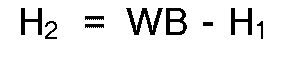
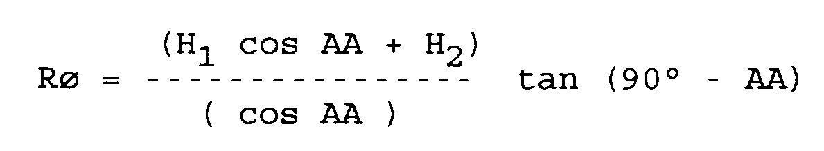
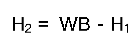
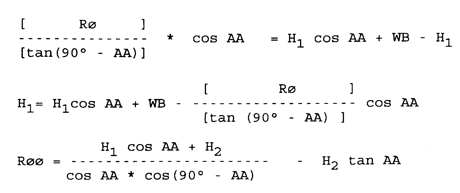
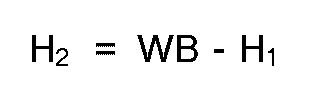
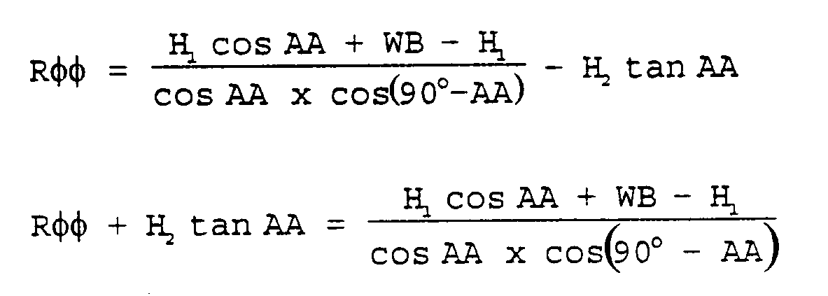
[0062] The following formulas show the dimensional relationship between the front mower and towed mower necessary to eliminate streaking in which:
Where Ro and Roo are such that R₃ - R₁ = R₄ - R₂
where WB = wheelbase
The formula describes in mathematic terms the relationship of the dimensions of the front and rear mower that must be maintained to accomplished tracking where the rear swaths will coincide with the front swath. The actual relationship between these components can be deviated from so long as the designed overlap in cutting swaths are adequate to compensate for these deviations. The cutting swaths of the rear cutters must always overlap the cutting swath of the front cutter so as to compensate for errors in the rear mower tracking behind the front mower. For example, when the mower assembly is operating on a sloped surface the towed mower tends to skid sideways down the sloped surface. Also when the mower assembly is driven at a fast pace through a turn the rear mower is urged by centrifugal force outwardly of the turn. Also there may be intentional and unintentional manufacturing deviations from the formula which cause the towed mower to incorrectly track behind the front mower.
[0063] The invention has been disclosed with the internal combustion engine 31 and pumps 32, 33 and 34 serving as power means for operating the hydraulic motor 45, power steering cylinders, hydraulic cylinders 70, 71, 83, 84 and 124. Additional pumps can be mounted to the cluster of pumps 32-34, if desired so as to provide more sources of power, as may be desired. The hydraulic conduits which extend from the pumps to the motors and cylinders have not been shown to simplify the drawings. However, it will be understood by those skilled in the art that other power units can be utilized, if desired. For example, a separate internal combustion engine can be mounted to the towed mower unit and can provide the power for the cutters of the side segments. Further, when the towed mower is used behind the type of power unit that includes a mechanical power take-off system, a conventional gearbox and shafts extending from the gearbox out to the cutting blades of each side frame segment can be used.
[0064] Further, the front mower can comprise the type of mower that includes a support frame with one or more cutters suspended from the frame.
1. In combination a self propelled front mower (21) and a towed rear mower (22) for cutting
grass and other vegetation, said front mower (21) including rear driving wheels (24,
25) engaging the ground surface for moving the front mower (21) in a forward direction
and a front cutter means (30) arranged for cutting a swath in the grass and like vegetation
beneath the front mower (21), said rear mower (22) including a support frame (61)
extending laterally on opposite sides of the cutting width of the front cutter means
(30), wheel means (75, 76) supporting said support frame (61) on the ground surface,
rear cutters (138a, 138b) mounted to said support frame (61) and spaced from each
other on opposite sides of the cutting width of the front mower (21) by a distance
so that the cutting width of each rear cutter (138a, 138b) partially overlaps the
cutting width of the front cutter means (30) when the front mower (21) moves in a
forward direction, connecting means (44) connecting said rear mower (22) to said front
mower (21) in trailer fashion and containing a vertical pivot axis (114), and power
means for driving said driving wheels (24, 25), said front cutter means (30) and said
rear cutters (138a, 138b),
characterized in that the distance (H1) between said pivot axis (114) and the axis of rotation of the rear driving wheels (24, 25) of the front mower (21) and the distance (H2) between said pivot axis (114) and the axis of rotation of said wheel means (75, 76) of said support frame (61) of said rear mower (22) are such that the cutting widths of said rear cutters (139a, 138b) are in straddling overlapped relationship with the cutting width of said front cutter means (30) even when the front mower (21) and the rear mower (22) move through a turn.
characterized in that the distance (H1) between said pivot axis (114) and the axis of rotation of the rear driving wheels (24, 25) of the front mower (21) and the distance (H2) between said pivot axis (114) and the axis of rotation of said wheel means (75, 76) of said support frame (61) of said rear mower (22) are such that the cutting widths of said rear cutters (139a, 138b) are in straddling overlapped relationship with the cutting width of said front cutter means (30) even when the front mower (21) and the rear mower (22) move through a turn.
2. The combination of claim 1 and wherein said power means is characterized by an internal
combustion engine (31) mounted to said front mower (21) in a position in front of
said driving wheels (24 and 25), and wherein said front cutter means (30) comprises
at least one rotary cutter (53a, 53b, or 53c) positioned in front of said internal
combustion engine (31).
3. The combination of claim 2 and wherein said front mower (21) is further characterized
by a power unit (29), with said internal combustion engine (31) and said driving wheels
(24 and 25) mounted on said power unit (29), and pivot connecting means (36) connecting
together said power unit (29) and said front cutter means (30) about an axis (38)
extending longitudinally with respect to the forward direction of movement of said
front mower (21).
4. The combination of claim 1 and wherein the support frame (61) of said rear mower (22)
is characterized by three laterally extending segments (62, 63, and 64) including
a central segment (62) and side segments (63 and 64) positioned on opposite sides
of said central segment (62), said side segments (63 and 64) each movably connected
to said central segment (62) and with each segment (62, 63, and 64) including wheels
(75, 76, 126, and 127) or the like for supporting the rear portions of the segments
(62, 63, and 64) from the ground surface.
5. The combination of claim 4 and further characterized by connecting means (44) pivotally
connecting the forward portion of the central segment (62) of said support frame (61)
to said front mower (21) adjacent the rear driving wheels of said front mower (21)
and wherein said connecting means applies a portion of the weight of said rear mower
(22) to the front mower (21) at the rear driving wheels (24 and 25) of the front mower
(21).
6. The combination of claim 4 and wherein said connecting means (44) is characterized
by an approximately U-shaped forward hitch member (86) connected at the free ends
of its side legs (87 and 88) to the front mower (21) at said rear driving wheels (24
and 25), and a universal joint (96) connected between said forward hitch member (86)
and the central segment (62) of said support frame (61) of said rear mower (22).
7. The combination of claim 6 and wherein said forward hitch member (86) is pivotally
connected to the front mower (21) at said rear driving wheels (24 and 25), and is
further characterized by a means (124) for adjusting the height of the support frame
(61) from the ground surface.
8. The combination of claim 1 and further characterized by pump means (32, 33, and 34)
mounted on said front mower (21) in driven relationship with respect to said drive
unit (29) and a hydraulic motor means (130) mounted on said rear mower (22) driven
by said pump means and in driving connection with the rear cutters (138a and 138b)
of said rear mower (22).
9. The combination of claim 4 and further characterized by hydraulic means (70 and 71)
for tilting said side segments (63 and 64) with respect to said central segment (62)
whereby the said segments (63 and 64) are lifted away from the ground surface and
the central segment (62) supports the side segments (63 and 64) from the ground surface.
10. The combination of claim 4 and wherein said power means is characterized by a hydraulic
motor (130) mounted to each side segment (63 and 64) and hydraulic transfer conduits
connected to each said hydraulic motor (130) and for connection to a source of fluid
pressure.
11. The combination of claim 4 and further characterized by at least one wheel means mounted
to each of said side frame segments (63 and 64), including a caster wheel (126 and
127) normally in engagement with the ground surface behind each of said side frame
segments (63 and 64), and wherein said wheel means mounted to said central frame segment
(62) comprises at least two wheels (75 and 76) mounted beneath said central frame
segment (62).
12. The combination of claim 6 and wherein central frame segment (62) is further characterized
by a ground engaging support means mounted at its forward end portion so that said
rear mower (22) is self supporting in a cutting attitude, and wherein said forward
hitch member (86) is pivotably mounted to said central frame segment (62) about a
laterally extending axis (108).
13. The combination of claim 12 and wherein said ground engaging support means comprises
a caster wheel (206 or 220).
14. The combination of claim 6 and wherein said forward hitch member (86) is pivotably
mounted to said front mower (21) about a laterally extending axis (97).
15. The combination of claim 1 and further characterized by pivot connecting means (36)
connecting together said power unit (29) and said front cutter means (30) about an
axis (38) extending longitudinally with respect to said power unit (29) and said front
cutter means (30).
16. The combination of claim 1 and wherein the structure of the front and rear mowers
are formed in accordance with:


Where Rø and Røø are such that R₃ - R₁ = R₄ - R₂

₁
where WB = wheelbase


Where Rø and Røø are such that R₃ - R₁ = R₄ - R₂
₁
where WB = wheelbase
1. Kombination eines selbstangetriebenen, vorderen Mähers (21) und eines mitgeschleppten,
hinteren Mähers (22) zum Schneiden von Gras und anderer Vegetation mit dem vorderen
Mäher (21), enthaltend hintere Antriebsräder (24, 25), die mit der Bodenoberfläche
in Eingriff stehen, um den vorderen Mäher (21) in Vorwärtsrichtung zu bewegen und
eine vordere Schneideinrichtung (30), die zum Schneiden einer Schwade in das Gras
oder ähnliche Vegetation unterhalb des vorderen Mähers (21) angeordnet ist, und mit
einem hinteren Mäher (22), enthaltend einen Trägerrahmen (61), der sich seitlich auf
beiden Seiten der Schneidbreite der vorderen Schneideinrichtung (30) erstreckt, Radmittel
(75, 76), die den Trägerrahmen (61) auf der Bodenoberfläche abstützen, hintere Schneidwerke
(138a, 138b), die an dem Trägerrahmen (61) befestigt sind und voneinander auf gegenüberliegenden
Seiten der Schneidbreite des vorderen Mähers (21) durch einen Abstand getrennt sind,
so daß die Schneidbreite jedes hinteren Schneidwerks (138a, 138b) teilweise die Schneidbreite
der vorderen Schneideinrichtung (30) überlappt, wenn der vordere Mäher (21) sich in
Vorwärtsrichtung bewegt, Verbindungsmittel (44) zum Anhängen des hinteren Mähers (22)
an den vorderen Mäher (21) nach Art eines Anhängers, die eine vertikale Drehachse
(114) aufweisen und Antriebsmittel zum Antreiben der Antriebsräder (24, 25), der vorderen
Schneideinrichtung (30) und der hinteren Schneidwerke (138a, 138b), dadurch gekennzeichnet,
daß der Abstand (H₁) zwischen der Drehachse (114) und der Rotationsachse der hinteren
Antriebsräder (24, 25) des vorderen Mähers (21). und der Abstand (H₂) zwischen der
Drehachse (114) und der Rotationsachse der Radmittel (75, 76) des Trägerrahmens (61)
des hinteren Mähers (22) so sind, daß die Schneidbreiten der hinteren Schneidwerke
(138a, 138b) die Schneidbreite der vorderen Schneideinrichtung (30) verbreitern und
überlappen, selbst wenn der vordere Mäher (21) und der hintere Mäher (22) sich durch
eine Kurve bewegen.
2. Kombination nach Anspruch 1, wobei die Antriebsmittel dadurch gekennzeichnet sind,
daß ein Innen-Verbrennungsmotor (31) am vorderen Mäher (21) in einer Stellung vor
den Antriebsrädern (24 und 25) angeordnet ist und wobei die vordere Schneideinrichtung
(30) wenigstens ein Rotationsschneidwerk (53a, 53b oder 53c) enthält, das vor dem
Innen-Verbrennungsmotor (31) angeordnet ist.
3. Kombination nach Anspruch 2, wobei der vordere Mäher (21) ferner dadurch gekennzeichnet
ist, daß er eine Antriebseinheit (29) aufweist, wobei der Innen-Verbrennungsmotor
(31) und die Antriebsräder (24 und 25) auf der Antriebseinrichtung (29) befestigt
sind und Drehverbindungsmittel (36) vorgesehen sind, die die Antriebseinrichtung (29)
und die vordere Schneideinrichtung (30) um eine Achse (38) miteinander verbinden,
die sich längs der Bewegung in Vorwärtsrichtung des vorderen Mähers (21) erstreckt.
4. Kombination nach Anspruch 1, wobei der Trägerrahmen (61) des hinteren Mähers (22)
dadurch gekennzeichnet ist, daß drei sich seitlich erstreckende Abschnitte (62, 63
und 64) vorgesehen sind, umfassend einen Zentralabschnitt (62) und Seitenabschnitte
(63 und 64), die auf gegenüberliegenden Seiten des Zentralabschnitts (62) angeordnet
sind, wobei die Seitenabschnitte (63 und 64) jeweils beweglich am Zentralabschnitt
(62) befestigt sind und jeder Abschnitt (62, 63 und 64). Räder (75, 76, 126 und 127)
oder ähnliches zum Abstützen des hinteren Bereichs der Abschnitte (62, 63 und 64)
von der Bodenoberfläche aufweisen.
5. Kombination nach Anspruch 4, gekennzeichnet durch Verbindungsmittel (44), die den
vorderen Bereich des Zentralabschnitts (62) des Trägerrahmens (61) drehbar mit dem
vorderen Mäher (21) in der Nähe der hinteren Antriebsräder des vorderen Mähers (21)
verbinden, wobei die Verbindungsmittel einen Teil des Gewichts des hinteren Mähers
(22) auf den vorderen Mäher (21) bei den hinteren Antriebsrädern (24 und 25) des vorderen
Mähers (21) aufbringen.
6. Kombination nach Anspruch 4, wobei das Verbindungsmittel (44) dadurch gekennzeichnet
ist, daß es ein ungefähr U-förmiges, vorderes Zugelement (86) aufweist, das mit den
freien Enden seiner Seitenschenkel (87 und 88) am vorderen Mäher (21) bei den hinteren
Antriebsrädern (24 und 25) befestigt ist und daß es ein Universalgelenk (96) aufweist,
das zwischen dem vorderen Zugelement (86) und dem Zentralabschnitt (82) des Trägerrahmens
(61) des hinteren Mähers (22) angeordnet ist.
7. Kombination nach Anspruch 6, wobei der vordere Zugteil (86) drehbar mit dem vorderen
Mäher (21) bei den hinteren Antriebsrädern (24 und 25) befestigt ist und ferner durch
ein Mittel (124) zum Einstellen der Höhe des Trägerrahmens (61) von der Bodenoberfläche
gekennzeichnet ist.
8. Kombination nach Anspruch 1, dadurch gekennzeichnet, daß Pumpeinrichtungen (32, 33
und 34) auf dem vorderen Mäher (21) befestigt sind, die in antriebsmäßigem Wirkzusammenhang
mit der Antriebseinheit (29) stehen und daß eine Hydraulik-Motoreinrichtung (130)
auf dem hinteren Mäher (22) befestigt ist, die durch die Pumpeinrichtungen angetrieben
wird und in Antriebsverbindung mit den hinteren Schneidwerken (138a und 138b) des
hinteren Mähers (22) steht.
9. Kombination nach Anspruch 4, ferner dadurch gekennzeichnet, daß Hydraulikmittel (70
und 71) zum Kippen der Seitenabschnitte (63 und 64) in bezug auf den Zentralabschnitt
(62) vorgesehen sind, wobei die Abschnitte (63 und 64) von der Bodenoberfläche abgehoben
sind und der Zentralabschnitt (62) die Seitenabschnitte (63 und 64) von der Bodenoberfläche
abstützt.
10. Kombination nach Anspruch 4, wobei das Antriebsmittel dadurch gekennzeichnet ist,
daß ein Hydraulikmotor (130) auf jedem Seitenabschnitt (63 und 64) befestigt ist und
Hydraulik-Übertragungsleitungen zur Verbindung mit einer Flüssigkeits-Druckquelle
mit jedem Hydraulikmotor (130) verbunden sind.
11. Kombination nach Anspruch 4, ferner durch wenigstens ein Radmittel gekennzeichnet,
das an jedem Seitenrahmenabschnitt (63, und 64) befestigt ist, enthaltend ein schwenkbares
Rad (126 und 127), das gewöhnlich in Eingriff mit der Bodenoberfläche hinter jedem
der Seitenrahmenabschnitte (63 und 64) steht, und wobei das am zentralen Rahmenabschnitt
(62) befestigte Radmittel wenigstens zwei unter dem zentralen Rahmenabschnitt (62)
befestigte Räder (75 und 76) aufweist.
12. Kombination nach Anspruch 6, wobei der zentrale Rahmenabschnitt (62) ferner dadurch
gekennzeichnet ist, daß ein mit dem Boden in Eingriff stehendes Haltemittel an seinem
vorderen Endabschnitt befestigt ist, so daß der hintere Mäher (22) in einer Schneidstellung
selbst abstützend ist und wobei das vordere Zugelement (86) um eine sich seitlich
erstreckende Achse (108) schwenkbar am zentralen Rahmenabschnitt (62) befestigt ist.
13. Kombination nach Anspruch 12, wobei die mit dem Boden in Eingriff stehenden Haltemittel
ein schwenkbares Rad (206 oder 220) aufweisen.
14. Kombination nach Anspruch 6, wobei das vordere Zugelement (86) schwenkbar um eine
sich seitlich erstreckende Achse (97) am vorderen Mäher (21) befestigt ist.
15. Kombination nach Anspruch 1, ferner gekennzeichnet durch Schwenkverbindungsmittel
(36), das die Antriebseinheit (29) und die vordere Schneideinrichtung (30) um eine
Achse (38) miteinander verbinden, die sich bezüglich der Antriebseinheit (29) und
der vorderen Schneideinrichtung (30) in Längsrichtung erstreckt.
16. Kombination nach Anspruch 1, wobei der Aufbau des vorderen und hinteren Mähers wie
folgt gebildet wird:


Wobei für Rø und Røø gilt: R₃- R₁ = R₄ - R₂

₁
wenn WB = Achsabstand


Wobei für Rø und Røø gilt: R₃- R₁ = R₄ - R₂
₁
wenn WB = Achsabstand
1. Combinaison d'une faucheuse avant (21) automotrice et d'une faucheuse arrière (22)
tractée, pour couper l'herbe et des végétaux, la faucheuse avant (21) comportant des
roues motrices arrière (24, 25) coopérant avec la surface du sol pour faire avancer
la faucheuse avant (21) et des moyens de coupe avant (30) pour couper un andain dans
l'herbe ou végétation analogue sous la faucheuse avant (21), la faucheuse arrière
(22) comprenant un châssis de support (61) disposé latéralement de part et d'autre
de la largeur de coupe du moyen de coupe avant (30), des roues (75, 76) portant le
châssis de support (61) à la surface du sol, des couteaux arrière (138a, 138b) montés
sur le châssis de support (61) et espacés l'un de l'autre des côtés opposés de la
largeur de coupe de la faucheuse avant (21) d'une distance telle que la largeur de
coupe de chaque couteau arrière (138a, 138b) chevauche pratiquement la largeur de
coupe du moyen de coupe avant (30) lorsque la faucheuse avant (21) avance, les moyens
de liaison (44) reliant la faucheuse arrière (22) à la faucheuse avant (21) par attelage
et comportant un axe de pivotement vertical (114) ainsi qu'un moyen d'entraînement
pour entraîner les roues motrices (24, 25), le moyen de coupe avant (30) et les moyens
de coupe arrière (138a, 138b), combinaison caractérisée en ce que la distance (H1)
entre l'axe de pivotement (114) et l'axe de rotation des roues d'entraînement arrière
(24, 25) de la faucheuse avant (21) et la distance (H2) entre l'axe de pivotement
(114) et l'axe de rotation des roues (75, 76) du châssis de support de la faucheuse
arrière (22) sont telles que les largeurs de coupe des moyens de coupe arrière (138a,
138b) chevauchent la largeur de coupe du moyen de coupe avant (30) même lorsque la
faucheuse avant (21) et la faucheuse arrière (22) décrivent un virage.
2. Combinaison selon la revendication 1, caractérisée en ce que le moyen d'entraînement
est un moteur à combustion interne (31) monté sur la faucheuse avant (21) devant les
roues motrices (24, 25) et le moyen de coupe avant (30) comporte au moins un moyen
de coupe rotatif (53a, 53b, 53c) placé à l'avant du moteur à combustion interne (31).
3. Combinaison selon la revendication 2, caractérisée en ce que la faucheuse avant (21)
comporte une unité motrice (29), le moteur à combustion interne (31) et les roues
motrices (24, 25) étant montés sur cette unité motrice (29) et un moyen de pivotement
(36) reliant l'unité motrice (29) et le moyen de coupe avant (30) autour d'un axe
(38) s'étendant longitudinalement par rapport à la direction d'avancée de la faucheuse
avant (21).
4. Combinaison selon la revendication 1, caractérisée en ce que le châssis de support
(61) de la faucheuse arrière (22) comporte trois segments s'étendant latéralement
(62, 63, 64) avec un segment central (62) et deux segments latéraux (63, 64) de part
et d'autre du segment central (62), les segments latéraux (63, 64) étant reliés de
manière mobile chacun au segment central (62) et chaque segment (62, 63, 64) comportant
les roues (75, 76, 126, 127) ou analogues pour porter les parties arrière des segments
(62, 63, 64) à la surface du sol.
5. Combinaison selon la revendication 4, caractérisée en ce que le moyen de liaison (44)
relient de manière pivotante la partie avant du segment central (62) du châssis de
support (61) à la faucheuse avant (21) de manière adjacente aux roues motrices arrière
de la faucheuse avant (21), et en ce que ce moyen de liaison applique une fraction
du poids de la faucheuse arrière (22) à la faucheuse avant (21) au niveau des roues
motrices arrière (24, 25) de la faucheuse avant (21).
6. Combinaison selon la revendication 4, caractérisée en ce que le moyen de liaison (44)
est un élément d'attelage avant (86) ayant sensiblement une forme de U relié par les
extrémités libres de ses branches latérales (87, 88) à la faucheuse avant (21) au
niveau des roues motrices arrière (24, 25) et un joint universel (96) est prévu entre
l'élément d'attelage avant (86) et le segment central (62) du châssis de support (61)
de la faucheuse arrière (22).
7. Combinaison selon la revendication 6, caractérisée en ce que l'élément d'attelage
avant (86) est relié en pivotement à la faucheuse avant (21) au niveau des roues motrices
arrière (24, 25) et un moyen (124) est prévu pour régler la hauteur du châssis de
support (61) par rapport à la surface du sol.
8. Combinaison selon la revendication 1, caractérisée par des pompes (32, 33,34) prévues
sur la faucheuse avant (21) en étant entraînées par l'unité motrice (29) et un moteur
hydraulique (130) monté sur la faucheuse arrière (22) en étant entraîné par la pompe
et en coopérant en entraînement avec les couteaux arrière (138a, 138b) de la faucheuse
arrière (22).
9. Combinaison selon la revendication 4, caractérisée par un moyen hydraulique (70, 71)
pour faire basculer les segments latéraux (63, 64) par rapport au segment central
(62), les segments (63, 64) étant relevés du sol et le segment central (62) portant
les segments latéraux (63, 64) à la surface du sol.
10. Combinaison selon la revendication 4, caractérisée en ce que le moyen d'entraînement
est un moteur hydraulique (130) monté sur chaque segment latéral (63, 64) et des conduites
de transfert hydrauliques étant reliées à chaque moteur hydraulique (130) et à une
source de fluide sous pression.
11. Combinaison selon la revendication 4, caractérisée par au moins un moyen à roues monté
sur chacun des segments de châssis latéral (63, 64) et comprenant une roue folle (126,
127) touchant normalement la surface du sol derrière chaque segment de châssis latéral
(63, 64) et le moyen à roues monté sur le segment de châssis central (62) se compose
d'au moins deux roues (75, 76) montées sous le segment de châssis central (62).
12. Combinaison selon la revendication 6, caractérisée en ce que le segment de châssis
central (62) comporte un moyen de support touchant le sol, pour son extrémité avant
de façon que la faucheuse arrière (22) soit auto-portée en position de coupe et l'élément
d'attelage avant (86) est monté de manière pivotante sur le segment de châssis central
(62) autour d'un axe (108) s'étendant latéralement.
13. Combinaison selon la revendication 12, caractérisée en ce que le moyen de support
s'appuyant sur le sol est une roue libre (206) ou (220).
14. Combinaison selon la revendication 6, caractérisée en ce que l'élément d'attelage
avant (86) est monté pivotant sur la faucheuse avant (21) autour d'un axe s'étendant
latéralement (97).
15. Combinaison selon la revendication 1, caractérisée par un moyen de liaison pivotant
(36) reliant l'unité motrice (29) et le moyen de coupe avant (30) autour d'un axe
(38) s'étendant longitudinalement par rapport à l'unité motrice (29) et le moyen de
coupe avant (30).
16. Combinaison selon la revendication 1, caractérisée en ce que la structure de la faucheuse
avant et celle de la faucheuse arrière sont liées par les formules suivantes dans
lesquelles :


où Ro et Roo sont tels que R₃ - R₁ = R₄ - R₂
₁
avec WB = empattement


où Ro et Roo sont tels que R₃ - R₁ = R₄ - R₂
₁
avec WB = empattement