(57) A projection-type color display device comprises light source means emitting three
light beams, each beam being of one of the three primary colors, a first, a second
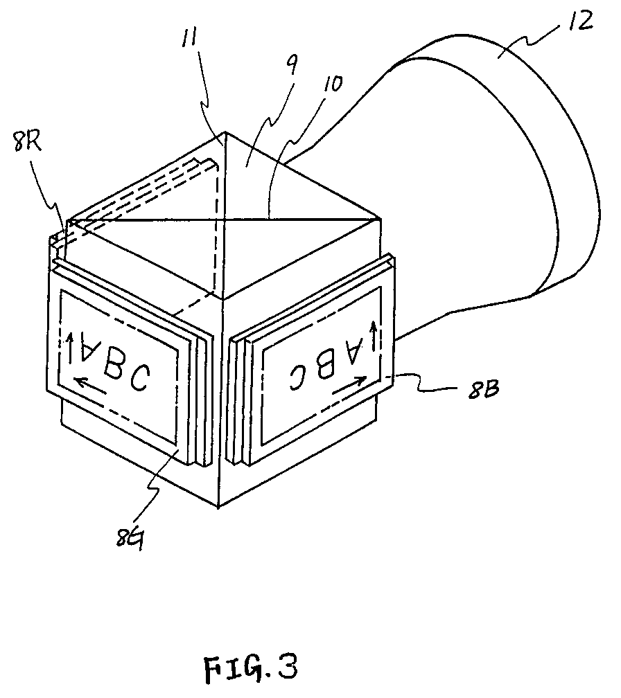
and a third liquid crystal light valve (8B, 8G, 8R) of an active matrix type, each
arranged to modulate a respective one of said liquid crystal light beams so as to
form modulated light beams containing images in the three primary colors, and each
including a light shielding layer on one side of a liquid crystal layer, dichroic
means (9) for synthesizing said images, said dichroic means reflecting the modulated
light beams from said second and third liquid crystal light valves and transmitting
the modulated light beam from said first liquid crystal light valve, wherein the images
included in the modulated light beams from the second and third liquid crystal light
valves are laterally inverted with respect to that from the first liquid crystal light
valve so as to compensate for the image inversion caused by reflection by said dichroic
means, and driving means arranged to drive said liquid crystal light valves by scanning
their matrix arrangements. Each of said liquid crystal light valves is arranged to
have its light shielding layer facing the light incident side. In order to compensate
for the lateral inversion of the images from the second and third liquid crystal light
valves with respect to that of the first liquid crystal light valve, said driving
means is arranged such that the scanning direction of said second and third liquid
crystal light valves is reversed with respect to that of said first liquid crystal
light valve.
|
|
