|
(11) | EP 0 621 056 A1 |

| (12) | EUROPEAN PATENT APPLICATION |
|
|
|
|
|||||||||||||||||||||||||||
| (54) | Respiratory protective device |
| (57) There is disclosed a respiratory protective device, and a related powered filtering
device. Known devices, suffer from a number of problems, such as liability to failure,
overworking and lack of fault indication. Accordingly, one aspect of the present invention
provides a respiratory protective device (5) providing a powered filtering device
(10) comprising a housing (15) having at least one inlet (20) and an outlet (25),
pump means (35) being provided between the at least one inlet and the outlet for pumping
air therebetween, a filter(s) being provided in association with the inlet(s) and/or
outlet, the outlet being connected to a first end (94) of a breathing hose (45), the
second end (96) of the breathing hose being connected to a facepiece (100), the powered
filtering device further comprising means (110) for controlling the pump means provided
at or near the outlet of the housing for controlling air flow between the inlet(s)
and the outlet(s) in response to a wearers breathing pattern. |
BACKGROUND
[0001] This invention relates to respiratory protective devices, and in particular to an improved powered filtering device for use in a respiratory protective device.
[0002] As far as is possible, the terminology herein adopted is in line with European Standard EN 132:1990 the object of which is to achieve a uniform interpretation of terms in this art so as to prevent ambiguous use of such terms.
[0003] Powered filtering devices or turbo filtering devices are known. In these devices air is delivered to a facepiece by means of a powered blower normally worn by the wearer by means of a body harness. The device may be connected to the facepiece by means of a breathing hose.
[0004] Powered filtering devices in some measure responsive to a wearers demand are also known. For example GB 2 032 284 B (RACAL) discloses breathing apparatus including detector means for detecting exhalation by the wearer connected to control means for at least reducing flow of air through filter means and flowing to the wearer during at least part of each exhale part of the breathing cycle of the wearer.
[0005] Such known devices suffer, however, from a number of problems/disadvantages. For example, in GB 2 032 284 B the detector means are positioned at or near an inlet to a hood or facemask, remote from the control means, and connected thereto by an electrical cable. The cable thus passes through a flexible breathing hose. The flexibility of the hose causes the cable to become weakened and liable to failure, in use.
[0006] It is, therefore, an object of one aspect of the present invention to obviate or mitigate the aforementioned problem/disadvantage.
[0007] Another problem with known powered filtering devices is that they tend to be wasteful in that they deliver air to a wearer when the wearer has no need of such air. This unnecessarily consumes filtration capacity and causes discomfort to the wearer.
[0008] Partially demand response devices, such as disclosed in GB 2 032 284 B (RACAL), go some way to mitigating this problem. However, these devices still waste valuable electrical energy by overworking the device.
[0009] It is, therefore, an object of another aspect of the present invention to obviate or mitigate the aforementioned problem.
[0010] A further disadvantage of many known powered filtering devices is that they provide no measurement of air flow. Thus, for example, a wearer may be provided with no indication of any fault occurring within the device such as a drop in the air flow rate below a minimum safe set level - for example, due to filter clogging.
[0011] It is, therefore, an object of another aspect of the present invention to obviate or mitigate the aforementioned disadvantage.
SUMMARY OF THE INVENTION
[0012] According to a first aspect of the present invention there is provided a respiratory protective device providing a powered filtering device comprising a housing having at least one inlet and an outlet, pump means being provided between the at least one inlet and the outlet for pumping air therebetween, a filter(s) being provided in association with the inlet(s) and/or outlet, the outlet being connected to a first end of a breathing hose, the second end of the breathing hose being connected to a facepiece, the powered filtering device further comprising means for controlling the pump means provided at or near the outlet of the housing for controlling air flow between the inlet(s) and the outlet in response to a wearers breathing pattern.
[0013] The facepiece, for example, may be a full face mask, half mask, quarter mask, mouthpiece assembly, helmet, hood, blouse or suit.
[0014] The control means preferably comprises a pressure sensor connected to a microcontroller, wherein, in use an electrical signal developed from the pressure sensor is periodically compared to a set reference level stored within the microcontroller and a corresponding error signal developed, the operation of the pump means being adjusted so as to seek to minimise the error signal.
[0015] The/each filter may be contained within a respective filter housing connectable to a respective inlet.
[0016] Alternatively, the/each filter may be contained within the housing of the powered filtering device.
[0017] According to a second aspect of the present invention there is provided a powered filtering device comprising a housing having at least one inlet and an outlet, pump means being provided between the at least one inlet and the outlet for pumping air therebetween, control means for controlling the pump means being provided at or near the outlet to the housing for controlling air flow between the inlet(s) and the outlet in response to a wearers breathing pattern.
[0018] According to a third aspect of the present invention there is provided a respiratory protective device providing a powered filtering device comprising a housing having at least one inlet and an outlet, pump means being provided between the at least one inlet and the outlet for pumping air therebetween, a filter(s) being provided in association with the inlet(s) and/or outlet, the outlet being connected to a first end of a breathing hose, the second end of the breathing hose being connected to a facepiece, the respiratory protective device further comprising means for controlling the pump means and thereby air flow between the inlet(s) and the outlet in response to a wearers past breathing pattern.
[0019] This respiratory protective device, therefore, operates by predicting the future breathing pattern based on the past breathing pattern.
[0020] The control means preferably comprises a pressure sensor connected to a microcontroller having means for storing data regarding a wearers past breathing pattern and means for predicting the wearers likely demand and controlling the pump means accordingly.
[0021] The pressure sensor is preferably located at or near the outlet of the powered filtering device. It should, however, be appreciated that the sensor may be suitably located within the breathing hose or within the facepiece.
[0022] According to a fourth aspect of the present invention there is provided a powered filtering device comprising a housing having at least one inlet and an outlet, pump means being provided between the at least one inlet and the outlet for pumping air therebetween, further comprising means for controlling the pump means and thereby air flow between the inlet(s) to the outlet in response to a wearers past breathing pattern.
[0023] The control means preferably comprises a pressure sensor located at the outlet to the housing connected to a microcontroller provided within the housing.
[0024] According to a fifth aspect of the present invention there is provided a respiratory protective device providing a powered filtering device comprising a housing having at least one inlet and an outlet, pump means being provided between the at least one inlet and the outlet for pumping air therebetween, a filter(s) being provided in association with the inlet(s) and/or outlet, the outlet being connected to a first end of a breathing hose, the second end of the breathing hose being connected to a facepiece, the respiratory protective device further comprising means for detecting if air flow through the respiratory protective device falls below a first set level, and means for controlling the pump means so as to seek to regain a preset air flow level above the first set level should the air flow fall below the first set level.
[0025] The detection means may further detect if air flow through the respiratory protective device falls below a second set level which second set level is below the first set level, the respiratory protective device further comprising means for alarming a wearer if the air flow falls below the second set level.
[0026] The detection means may comprise an air flow passage between the inlet(s) and the outlet having a thermistor located therein, the thermistor being connected to a microcontroller and to an audio and/or visual alarm, the microcontroller storing the first and second set levels, whereby in use a signal detected by the thermistor is compared to the set level(s) and the pump control means controls the pump means so as to seek to regain a preset air flow level above the first set level if the detected signal is less than the first set level or the alarm means activated if the detected signal is less than the second set level.
[0028] According to a sixth aspect of the present invention there is provided a powered filtering device comprising a housing having at least one inlet and an outlet, pump means being provided between the at least one inlet and the outlet for pumping air therebetween, the powered filtering device further comprising means for detecting if air flow through the device falls below a first set level, and means controlling the pump means so as to seek to regain a preset air flow level above the first set level should the air flow fall below the first set level.
[0029] The detection means may further detect if air flow through the respiratory protective device falls below a second set level which second set level is below the first set level, the respiratory protective device further comprising means for alarming a wearer if the air flow falls below the second set level.
BRIEF DESCRIPTION OF THE DRAWINGS
[0030] Embodiments of the invention will now be described, by way of example only, with reference to the accompanying drawings, which are:
- Fig 1
- a schematic view of a respiratory protective device according to one embodiment of the present invention;
- Fig 2
- a more detailed schematic view of the respiratory protective device of Fig 1;
- Fig 3(a)
- a partial cross-sectional side view of a secondary air flow passage provided in the respiratory protective device of Fig 1;
- Fig 3(b)
- a partial end view of the secondary air flow passage of Fig 3(a) along direction 'A';
- Fig 4
- a series of typical timing diagrams relating to the respiratory protection device of Fig 1 operating in a first mode by the so-called Integral or Integral Plus Bang methods; and
- Fig 5
- a series of typical timing diagrams relating to the respiratory protective device of Fig 1 operating in the first mode by the so-called 90° Phase Advance method.
DESCRIPTION OF EMBODIMENTS
[0031] Referring to the drawings, there is illustrated an embodiment of a respiratory protective device according to the present invention, generally designated 5, providing a powered filtering device 10, comprising a main housing 15 having (in this embodiment) two inlets 20 and an outlet 25. The housing 15 is made from a moulded plastic.
[0032] Between the inlets 20 and the outlet 25 there is provided a chamber 30. In the chamber 30 there is provided pump means in the form of an impeller (blower) 35. The impeller 35 is suitably mounted within the chamber 30 so as to be substantially coaxially mounted within the chamber 30 and rotatable therein. As can be seen best from Fig 2 the diameter of the impeller 35 is smaller than that of the chamber 30; thus an air flow passage 40 is defined between the outer circumference of the impeller 35, and the innermost cylindrical surface of the chamber 30.
[0034] Provided between the DC motor 35 and battery pack 50 is an electronic switch 51 and microcontroller 52. The purpose and functioning of the microcontroller 52 will be described in more detail hereinafter.
[0035] In this embodiment filter canisters (housings) 60 are connectable to the main housing 15 at each of the inlets 20. Each of the filter housings 60 may be attached to an inlet 20 by means of co-acting threaded portions 75,70 provided on an outer surface of the filter housing 60 at or near an outlet 84 thereof and an inner surface of the inlet 20.
[0036] Each filter canister 60 is suitably sized and shaped so as to retain a filter(s) (not shown) therein. Each filter canister 60 further has an inlet aperture 85. It can, therefore, be seen that an air path is formed via inlet apertures 85 through each filter housing 60 via the filter(s) (not shown) to outlet 84 and thence through inlet 20, impeller 35, and chamber 40 to outlet 25.
[0037] The main housing 15 and the battery pack 50 may each have means by which they can be retained on a body harness - which in this embodiment is in the form of a belt 90.
[0038] The outlet 25 is connected to a first end 94 of a flexible breathing (air supply) hose 95. The breathing hose 95 may be corrugated. A second end 96 of the breathing apparatus hose 95 is connected to an inlet of a facepiece - which in this embodiment is a full face mask 100 having a head harness 105.
[0039] At or near the outlet 25 there is provided means for controlling the impeller 35 in response to a wearers inhalation requirements comprising a pressure sensor 110 which is connected to the microcontroller 52 via a first signal conditioner 115. The signal conditioner 115 includes an amplifying function.
[0040] A mode selector switch (not shown) may be provided on the housing 15 to allow a wearer to switch the respiratory protective device between first or second mode of operation.
FIRST MODE OF OPERATION
[0041] In use in the first mode of operation, an electrical signal developed by the pressure sensor 110 is periodically (eg. every 0.04 seconds) compared to a set reference level, the value of which is preprogrammed into the microcontroller 52, and a corresponding error signal developed. The microcontroller 52 can then employ the error signal to adjust the operation of the DC motor 45 controlling the impeller 35 thereby attempting to minimise the error signal. The apparatus 5, therefore, provides a breath responsive air supply. This is evidenced by Figs 4 and 5 which show, for differing methods of operation of the microcontroller 52: (a) a typical breathing cycle of a wearer; (b) pressure at the outlet 25, sensed by the pressure sensor 110; and (c) power consumed by the DC motor 45 when under the control of the microcontroller 52.
[0042] As can be seen from Fig 4, on inhalation the pressure at the sensor 110 drops, eventually dropping below the set point level. The microcontroller 52 seeks to increase the pressure at the sensor 110 back to the set point level by increasing the power to the motor 45, and thereby the motor speed.
[0043] Once the set point has been regained the power to the motor 45 is decreased to its original level.
[0044] A number of different methods of operation of the microcontroller 52 have been envisaged. These will be described in more detail hereinbelow.
Basic Integral Method
[0045] Referring to Fig 4, a first method of operation which has been devised - the so-called basic Integral Controller - is to calculate the error signal between the blower outlet pressure and the setpoint once every set period, eg. every 0.04 seconds. The error signal is then added to or subtracted from a variable Motor Speed and the motor speed updated accordingly.
[0046] The calculation given below is, therefore, performed once every set period:-
All these variables may be 8 or 16 bit integers. When Motor Speed = 0, the motor is fully on. When Motor Speed = 255, the motor is fully off. Therefore, when the blower outlet pressure is below the setpoint the Motor Speed should be adjusted as given in the formula above.
[0047] It has been found employing this method that the microcontroller 52 responds breath by breath to the breathing pattern.
[0048] The calculation can be enhanced by adding a gain to the error term, as given in the formula below:-
Integral Plus Bang Method
[0049] A problem with the basic Integral method of operation of the microcontroller 52 is that the motor speed only ramps up to full speed during the latter section of inhalation. This means that during the latter part of inhalation the motor 35 is still accelerating and not supplying as much air as could be possible.
[0050] To overcome this shortfall, a number of other control algorithms for the microcontroller 52 may be considered. All these algorithms attempt to supply more air during the latter part of the inhalation.
[0051] Previously, when using the blower with no microcontroller 52, it has been observed with a reasonable level of breathing, the pressure inside the mask 100 still went negative. This implies that there is no reason just to ramp up the motor speed during the start of the latter part of inhalation, but instead the motor unit should be turned fully on.
[0052] This is the reasoning behind the 'Integral Plus Bang' method of operation of the microcontroller 52. During rest and exhalation, the basic Integral controller described above would regulate the motor speed to maintain a constant pressure at the outlet 25.
[0053] To detect the start of inhalation, the blower outlet 25 pressure was compared to the setpoint. If the outlet pressure fell below a threshold level, the microcontroller 52 would turn the motor 45 fully on as described below:-
If (Setpoint - Blower Outlet Pressure) < Threshold then
Else
turn motor full on
This gives more of a boost to the impeller 35 at the start of the latter part of inhalation. With this method, there is of course the drawback of increased power consumption.
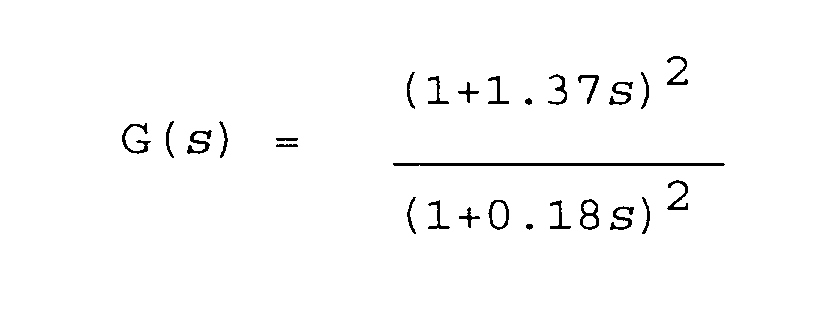
90° Phase Advance Method
[0054] Referring to Fig 5, a further method - which may be called the "90° Phase Advance Controller" - uses the fact that the wearers breathing pattern, and therefore the error signal is periodic with a frequency range of typically 0.3 to 6 rad/sec. By leading the phase of the error signal, then the speed of the motor 45 can be ramped up in anticipation of the start of a breath. A phase lead controller has been calculated for a 90° phase lead over this frequency range and centred on 2 rad/sec. This gave the following transfer function (G) of time (s):
Using a sample frequency of 25Hz, the phase lead controller can be converted using a bilinear conversion to the following digital filter:-
where, k = a constant
The above filter includes a gain compensation to reduce the gain at high frequency.
[0055] The Phase Advance Controller can be coded using a fixed point arithmetic to give accuracy to the coefficients of the equation. Full IEEE floating point algorithms could alternatively be used.
[0056] Implementation problems have been found in the 90° phase lead controller. A simpler 45° phase lead controller can therefore be designed. This gave the following transfer function:
Again as in the basic Integral controller, the motor 45 power would be ramped up during inhalation, but not rapidly enough to satisfy the demand.
SECOND MODE OF OPERATION
[0058] Referring again to Fig 2, the device 5 further comprises means for detecting if air flow through the device 5 falls below a first set level, and means for controlling the impeller 35 so as to seek to regain a preset air flow level above the first set level should the air flow fall below the first set level. The detection means may further detect if air flow through the respiratory protective device falls below a second set level which second set level is below the first set level, the respiratory protective device further comprising means for alarming a wearer if the air flow falls below the second set level. Air fow reduction could be due to, for example, either filter clogging during use or replacement of a filter(s) with a filter(s) of greater resistance to air flow.
[0059] The detection means comprises a secondary air flow passage 116 near the outlet 25, which passage 116 communicates at either end with a primary air flow passage 117 to the outlet 25. The secondary passage 116 has a flow sensor in the form of a thermistor 120 located therein. The thermistor 120 is connected to the microcontroller 52, a second signal conditioner 125 and an audio/visual alarm 130. The microcontroller 52 is preprogrammed with first and second set levels and with a preset air flow level.
[0060] In use in the second mode of operation, the apparatus 5 does not provide a breath responsive air supply. Rather a signal detected by the thermistor 120 is compared to both of the set levels. If the detection signal is less than the first set level then the microcontroller 52 acts to increase the speed of the impeller 35 so as to seek to increase the air flow to the preset air flow level.
[0061] During usage the filter(s) may become clogged or blocked. This may prevent the air flow being increased to the preset air flow level. In this event the detected signal may fall below the second set level. In such case the alarm 130 will be activated thereby warning the wearer of low air flow.
[0062] The thermistor 120 is (in this embodiment) a small bead thermistor, such as that produced by Fenwal® Electronics Inc under their code number 111 202 CAK RO1. Alternatively, a so-called Betacurve small precision matched NTC, R-T curve matched thermistor could be used.
[0063] The secondary air flow passage 116 may be formed in a number of different ways. Referring to Figs 3(a) and (b) there is illustrated one way of forming the secondary passage 116 on an inner side of a wall 135 of the primary air flow passage 117 employing a wall 140. The wall 140 is formed from integral semi-frustoconical and semi-cylindrical portions 145, 150 and provides an inlet 155 and an outlet 160. The thermistor 120 is suitably retained within the secondary passage 116.
1. A respective protective device providing a powered filtering device comprising a housing
having at least one inlet and an outlet, pump means being provided between the at
least one inlet and the outlet for pumping air therebetween, a filter(s) being provided
in association with the inlet(s) and/or outlet, the outlet being connected to a first
end of a breathing hose, the second end of the breathing hose being connected to a
facepiece, the powered filtering device further comprising means for controlling the
pump provided at or near the outlet of the housing for controlling air flow between
the inlet(s) and the outlet in response to a wearers breathing pattern.
2. A respiratory protective device as claimed in claim 1, wherein the facepiece is selected
from one of a full mask, half mask, quarter mask, mouthpiece assembly, helmet, hood,
blouse or suit.
3. A respiratory protective device as claimed in any preceding claim, wherein the control
means comprises a pressure sensor connected to a microcontroller, wherein, in use
an electrical signal developed from the pressure sensor is periodically compared to
a set reference level stored within the microcontroller and a corresponding error
signal developed, the operation of the pump means being adjusted so as to seek to
minimise the error signal.
4. A respiratory protective device as claimed in any of claims 1 to 3, wherein the/each
filter is contained within a respective filter housing connectable to a respective
inlet.
5. A respiratory protective device as claimed in any of claims 1 to 3 , wherein the/each
filter is contained within the housing of the powered filtering device.
6. A respiratory protective device as claimed in any preceding claim, wherein the control
means controls the pump means in response to a wearers past breathing pattern.
7. A respiratory protective device as claimed in any preceding claim, wherein the respiratory
protective device further comprises means for detecting if air flow through the respiratory
protective device falls below a set level, and means for alarming a wearer if the
air flow falls below the set level.
8. A powered filtering device comprising a housing having at least one inlet and an outlet,
pump means being provided between the at least one inlet and the outlet for pumping
air therebetween, control means for controlling the pump means being provided at or
near the outlet to the housing for controlling air flow between the inlet(s) and the
outlet in response to a wearers breathing pattern.
9. A respiratory protective device providing a powered filtering device comprising a
housing having at least one inlet and an outlet, pump means being provided between
the at least one inlet and the outlet for pumping air therebetween, a filter(s) being
provided in association with the inlet(s) and/or outlet, the outlet being connected
to a first end of a breathing hose, the second end of the breathing hose being connected
to a facepiece, the respiratory protective device further comprising means for controlling
the pump means and thereby air flow between the inlet(s) and the outlet in response
to a wearers past breathing pattern.
10. A respiratory protective device as claimed in claim 9, wherein the control means comprises
a pressure sensor connected to a microcontroller having means for storing data regarding
a wearers past breathing pattern and means for predicting the wearers likely demand
and controlling the pump means accordingly.
11. A respiratory protective device as claimed in either of claims 9 or 10, wherein the
control means are provided at or near the outlet of the housing.
12. A respiratory protective device as claimed in any of claims 9 to 11, wherein the facepiece
is selected from one of a full mask, half mask, quarter mask, mouthpiece assembly,
helmet, hood, blouse or suit.
13. A respiratory protective device as claimed in claim 10 or claim 11 or 12 when dependent
upon claim 10, wherein an electrical signal developed from the pressure sensor is
periodically compared to a set reference level stored within the microcontroller and
a corresponding error signal developed, the operation of the pump means being adjusted
so as to minimise the error signal.
14. A respiratory protective device as claimed in any of claims 9 to 13, wherein the means
for controlling the pump means controls the pump means by the transfer function (G)
of time (s):
15. A powered filtering device comprising a housing having at least one inlet and an outlet,
pump means being provided between the at least one inlet and the outlet for pumping
air therebetween, further comprising means for controlling the pump means and thereby
air flow between the inlet(s) and the outlet in response to a wearers past breathing
pattern.
16. A respiratory protective device providing a powered filtering device comprising a
housing having at least one inlet and an outlet, pump means being provided between
the at least one inlet and the outlet for pumping air therebetween, a filter(s) being
provided in association with the inlet(s) and/or outlet, the outlet being connected
to a first end of a breathing hose, the second end of the breathing hose being connected
to a facepiece, the respiratory protective device further comprising means for detecting
if air flow through the respiratory protective device falls below a first set level,
and means controlling the pump means so as to seek to regain a preset air flow level
above the first set level should the air flow fall below the first set level.
17. A respiratory protective device as claimed in claim 16, wherein the detection means
further detects if air flow through the respiratory protective device falls below
a second set level which second set level is below the first set level, the respiratory
protective device further comprising means for alarming a wearer if the air flow falls
below the second set level.
18. A respiratory protective device as claimed in claim 17, wherein the detection means
comprises an air flow passage between the inlet(s) and the outlet having a thermistor
located therein, the thermistor being connected to a microcontroller and to an audio
and/or visual alarm, the microcontroller storing the first and second set levels,
whereby in use a signal detected by the thermistor is compared to the stored set level(s)
and the pump control means controls the pump means so as to seek to regain a preset
air flow level above the first set level if the detected signal is less than the first
set level or the alarm means is activated if the detected signal is less than the
second set level.
19. A respiratory protective device as claimed in any of claims 16 to 18, wherein the
detection means is located at or near the outlet.
20. A respiratory protective device as claimed in any of claims 16 to 19, wherein the
facepiece is selected from one of a full mask, half mask, quarter mask, mouthpiece
assembly, helmet, hood, blouse or suit.
21. A powered filtering device comprising a housing having at least one inlet and an outlet,
pump means being provided between the at least one inlet and the outlet for pumping
air therebetween, the powered filtering device further comprising means for detecting
if air flow through the device falls below a first set level, and means for controlling
the pump means so as to seek to regain a preset air flow level above the first set
level should the air flow fall below the first set level.