|
(11) | EP 0 553 153 B1 |

| (12) | EUROPEAN PATENT SPECIFICATION |
|
|
| (54) |
METHOD OF OPERATING MULTI-CHANNEL ARRAY DROPLET DEPOSITION APPARATUS BETRIEBSVERFAHREN FÜR EIN VIELKANALIGES GERÄT ZUM NIEDERSCHLAG VON TRÖPFCHEN PROCEDE DE FONCTIONNEMENT D'UN APPAREIL DE DEPOT DE GOUTTELETTES PAR RESEAU MULTICANAL |
|
|
|||||||||||||||||||||||||||||||
| Note: Within nine months from the publication of the mention of the grant of the European patent, any person may give notice to the European Patent Office of opposition to the European patent granted. Notice of opposition shall be filed in a written reasoned statement. It shall not be deemed to have been filed until the opposition fee has been paid. (Art. 99(1) European Patent Convention). |
[0001] This invention relates to multi-channel array droplet deposition apparatus and, more particularly, to a method of operating such apparatus of the kind comprising an array of parallel channels, respective nozzles communicating with said channels for ejection of droplets of liquid from the channels, droplet liquid supply means connected with the channels and electrically actuable means located in relation to said channels to impart energy pulses to respective selected channels for effecting droplet ejection from the nozzles of the channels selected. A particular case of droplet deposition apparatus of the kind set forth is the, so-called, drop-on-demand ink jet printhead. The need exists to print ink dots in response to electronic print data at a high resolution, less than is readily resolved by the eye at a convenient reading distance. Many types of ink jet array have been proposed including United States Patent No. 4,296,421 which operates on the thermal bubble jet principle and United States Patent 4,584,590 which discloses one form of piezo-electric shear mode activated array. A further type of shear mode actuated array in which piezo-electric shear mode actuated channel dividing walls are employed is disclosed in United States Patents 4,879,568 and 4,887,100 assigned to the applicants.
[0002] In the piezo-electric shared wall actuator array disclosed in US 4,887,100 it is preferred that the wall actuators are compliant, firstly because this leads to a higher linear density of channels and therefore assists to produce a high print resolution. A further reason is that the transduction of energy from the actuating voltage to pressure in the ink channels and subsequently to the ejection of ink from the nozzle to form drops is most efficient when the walls are compliant. In this type of wall actuator it may accordingly be chosen in order to satisfy this condition that the value of:
is in the range 0.2 <K<2. The operating state requiring maximum operating voltage occurs when all the odd (or even) numbered channels are actuated. The minimum value of this voltage occurs when K = 0.5. It was also apparent that crosstalk between channels increases as the compliance increases. It is important that an ink droplet should be ejected only from those channels that are selected for printing and that pressure developed through crosstalk is maintained safely below the level that might cause a spurious drop to be ejected. In US 4,887,100 (Col. 5, L40-50 and Col. 15, L15-23), it was indicated that there would generally be a limiting compliance where crosstalk would make operation impractical. However, a method was described therein by reference to Figure 9 whereby crosstalk could be eliminated mechanically and operation could then take place without regard to the effect of compliance on crosstalk.
[0003] It was also recognised that crosstalk due to wall compliance could, in principle, be compensated by choosing an appropriate array of voltage values and a method of generating such voltage values is disclosed in US Patent No. 5,028,812.
[0004] The presence of crosstalk due to wall compliance in ink jet printheads which are constructed with inactive walls between adjacent ink channels has not been reported in the literature. Such printheads include the thermal bubble jet and piezo-electric roof mode constructions. The absence of reports of crosstalk in these cases could be attributable to constructions in which the walls between adjacent channels are substantially rigid. In that case the channels are more widely separated than is necessary. After adopting the results of the present invention higher density array printheads substantially free of crosstalk can be constructed.
[0005] Compliant crosstalk, however, is disclosed in United States Patent 4,381,295. This reference describes moreover a method of compensating for what is referred to as both positive and negative crosstalk, by introducing a network of compensating passive resistors. This proposal however is not applicable to the type of array disclosed in United States Patent 4,887,100, since this array incorporates capacitors (representing the piezo-electric actuators), which are in parallel with the actuating signal lines. In United States Patent No. 4,381,295, the actuators are in series with the signal lines. Nor is it relevant to arrays such as United States Patent No. 4,296,421 where the actuating elements are resistive elements.
[0006] It is an object of the present invention to provide a method of operating droplet deposition apparatus of the kind set forth which achieves substantially improved reduction of crosstalk. A further object is to achieve by an exclusively electrical method the said substantial reduction of crosstalk.
[0007] The present invention consists in the method of operating a multi-channel array pulsed droplet deposition apparatus comprising an array of parallel channels, channel walls each separating one channel of the array from an adjacent channel in the array, the channel walls having a wall compliance, respective nozzles communicating with said channels for ejection of droplets of liquid from the channels, droplet liquid supply means connected with the channels for the supply to the channels of droplet liquid having a liquid compliance and electrically actuable means located in relation to said channels for imparting energy pulses to droplet liquid in the channels so that droplets are ejected from the nozzles of selected ones of the channels, characterised by comprising the steps of applying through said electrically actuable means energy pulses of a first amplitude to the droplet liquid in selected ones of the channels of the array and applying through said electrically actuable means energy pulses of a second amplitude to the liquid in at least some others of the channels in the array in the vicinity of said selected channels said first and second amplitudes being dependent upon a ratio of said wall compliance and said liquid compliance, to produce a pressure distribution in the channels of the array which effects droplet ejection from only said selected channels and is substantially free from pressure crosstalk between said selected channels or between said selected channels and other channels of the array.
[0008] The invention also consists in the method of operating a multi-channel array pulsed droplet deposition apparatus comprising an array of parallel channels, channel walls each separating one channel of the array from an adjacent channel in the array, the channel walls having a wall compliance, respective nozzles communicating with said channels for ejection of droplets of liquid from the channels, droplet liquid supply means connected with the channels for the supply to the channels of droplet liquid having a liquid compliance and electrically actuable means located in relation to said channels for imparting energy pulses to droplet liquid in the channels so that droplets are ejected from the nozzles at selected ones of the channels characterised by comprising the steps of applying through said electrically actuable means energy pulses of a first amplitude to the droplet liquid in selected ones of the channels of the array and applying through said electrically actuable means energy pulses of a second amplitude to the liquid in at least some others of the channels in the array in the vicinity of said selected channels, said first and second amplitudes being dependent upon a ratio of said wall compliance and said liquid compliance, to develop a distribution of potential energy stored in the channels to which said pulses are applied which effects droplet ejection only from said selected channels at substantially uniform momentum between said selected channels.
[0009] Advantageously, the step of applying energy pulses through said electrically actuable means comprises applying unipolar voltages for each of said channels.
[0010] Suitably, said unipolar voltages are formed by adding a constant voltage to each of the channel voltages.
[0011] In one form of the method of the invention in which channel walls of the droplet deposition apparatus are compliant and each are provided with said electrically actuable means so that actuation of opposed side walls by said electrically actuable means effects droplet expulsion from a channel therebetween, the channels being divided into two groups of which the channels of one group alternate with those of the other group, a scheme of voltage actuation to reduce crosstalk is employed that generates array pressures at least in a region of the array including actuated channels, as follows,
| Type of Channel | Actuated Neighbours | Applied Pressure |
| Actuated Group | ||
| Actuated | - | P |
| Non-Actuated | - | 0 |
| Non-Actuated Group | 2 | -P |
| 1 | -P/2 | |
| 0 | 0 |
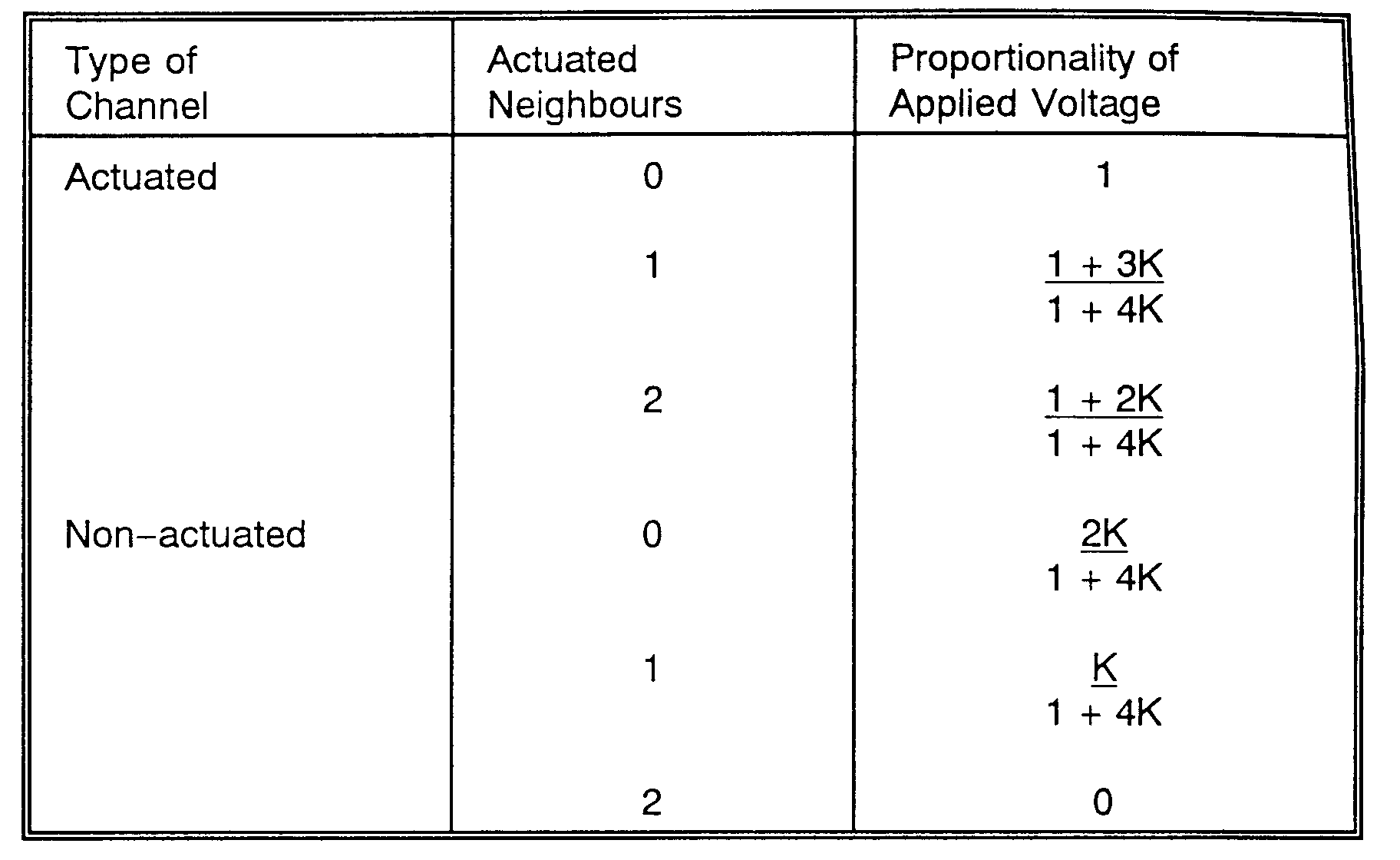
[0012] Preferably said scheme of voltage actuation is as follows:
| Type of Channel | Actuated Neighbour | Proportionality of Applied Voltage |
| Actuated Group | ||
| Actuated | - | 1 + 2K |
| Non-Actuated | - | 0 |
| Non-Actuated Group | 2 | -2K |
| 1 | -K | |
| 0 | 0 |
[0013] In another form of the invention in which the channel array comprises open topped channels formed in a base from which compliant inactive channel dividing side walls are upstanding the open topped channels being closed by an active wall means actuable by said electrically actuable means, the method is characterised by applying actuating voltages using said electrically actuable means.
[0014] The invention also consists in the method of operating a multi-channel array droplet deposition apparatus comprising an array of parallel channels uniformly spaced by channel separating side walls, said side walls having a wall compliance, respective nozzles communicating with said channels for ejection of droplets of liquid from the channels, droplet liquid supply means connected with the channels for the supply to the channels of droplet liquid having a liquid compliance and electrically actuable means located in relation to said channels for imparting energy pulses to droplet liquid in the channels to effect droplet ejection from the channels, characterised by comprising the steps of selecting a group of successive ones of the channels of the array and applying to the channels of said group through said electrically actuable means energy pulses of a first amplitude to effect in a first half cycle of operation droplet ejection from alternate ones of the channels of the selected group and in a second half cycle of operation droplet ejection from remaining ones of the channels of the group; and applying to channels at opposite sides of said selected group of channels energy pulses of a second amplitude, said first and second amplitudes being so dependent on a ratio of said wall compliance and liquid compliance as to compensate for pressure cross-talk between channels of the selected group or between said selected group of channels and other channels of the array.
[0015] The invention will now be described by way of example with reference to the accompanying drawing which is a transverse cross sectional view of a droplet deposition apparatus, suitably, a drop-on-demand ink jet printer of the kind described in United States Patent No. 4,887,100.
[0016] The multi-channel array droplet deposition apparatus, a section of which is illustrated in the drawing, comprises an array of eleven channels numbered 1 to 11 of which, for example, channels 3, 7 and 9 are actuated by shear mode displacement of opposite side walls of those channels. The arrangement is typically disclosed in U.S. Patent 4,887,100. The channels of the array comprise two groups each of alternate channels, the odd numbered channels forming one and the even numbered channels the other such group. At each printing operation selected channels of one group are actuated and at the next printing operation selected channels of the other group are actuated. It will be apparent, accordingly, that each channel dividing side wall forms part of the actuating means of the channels on opposite sides thereof.
[0017] If the channel dividing side walls, which are the channel actuators, are rigid, that is to say, if they can be displaced each in response to an actuation voltage applied to electrodes on opposite, channel facing side walls thereof and have zero compliance in response to pressure, then the pattern of actuation and the channel pressures take the form
| Channel number | 1 | 2 | 3 | 4 | 5 | 6 | 7 | 8 | 9 | 10 | 11 |
| Channels actuated | * | * | * | ||||||||
| Channel pressures | 0 | P | 0 | P | -P | P | 0 |
and those not adjacent to any actuated channel a zero pressure.
[0018] This pressure pattern satisfies the condition of being free of crosstalk between actuated channels, since there is no overspill of pressure actuation from an actuated channel to another channel in the same (odd) group of channels. This pattern also satisfies the requirement when the walls have zero compliance that the channels, which are selected for actuation (i.e. the odd numbered channels 3, 7 and 9), each have equal stored potential energy and that the droplet momentum delivered into the respective nozzles of the selected channels by the action of the acoustic waves caused by actuation of the selected channels are substantially equal.
[0019] In an array with compliance ratio K the same pressure pattern satisfies the condition that the array simulates an array having zero compliance and is consequently "crosstalk free". Although the potential energy is now stored partially in the ink and partially in the walls, each channel has equal potential energy and the action of the acoustic waves again delivers the droplet momentum into the nozzles. One pattern of actuation voltages that satisfies the condition of estalishing the "crosstalk free" pressure pattern is a set of voltages in proportion to
| Channel number | 1 | 2 | 3 | 4 | 5 | 6 | 7 | 8 | 9 | 10 | 11 |
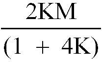
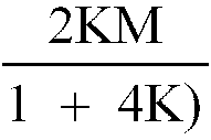
| Channel voltages | 0 | -K | (1+2K) | -K | 0 | -K | (1+2K) | -2K | (1+2K) | -K | 0 |
[0020] In this solution channel drive transistors 21 -31 in the drawing are obliged to handle both positive and negative voltages. It is more economical to use transistors of only one polarity to reduce the number of manufacturing steps when the transistor is an LSI integrated drive chip. If a constant voltage is added to all the channel voltages applied to the shared actuator array, it has no net effect on actuation. For example voltage 2K may be added to each channel voltage obtaining a set of voltages in proportion to
Channel voltage 2K K (1+4K) K 2K K (1+4K) 0 (1+4K) K 2K
This set of voltages also generates the previous pressure pattern that is free of crosstalk.
[0021] When the relationship between the actuation voltage V and the ink fluid velocity in the nozzle is analysed, the operating state requiring maximum operating voltage occurs when a series of adjacent odd (or even) numbered channels are actuated. The minimum value of this voltage occurs when the actuator, ink channel section and the nozzle size are chosen (that is to say are "matched") for optimum energy transfer.
[0022] In particular the matching condition can be expressed in terms of the compliance ratio K.
where (We) is the Weber Number or non dimensional velocity of ink flow through the nozzle, and where
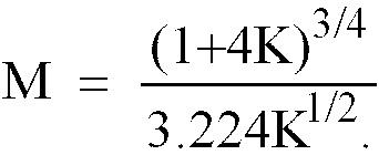
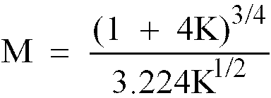
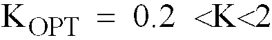
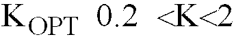
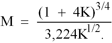
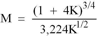
From this formula it is deducible that there exists a best compliance ratio KOPT where the actuation voltage is a minimum. This occurs, when a group of adjacent odd (or even) channels are actuated, at the value
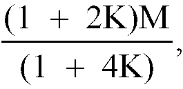
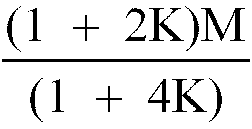
and M = 1.
In the region close to KOPT, the relationship for M can also be written in terms of (K/KOPT) in the form
in which again M = 1 when
. Calculation shows that the above expressions for M are not highly sensitive to K. Calculated values are
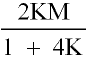
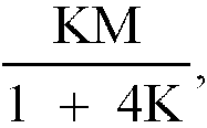
The set of voltages that generates the pressure pattern free of cross talk can therefore be normalised into a form in proportion to
[0023] Thus it is seen that the channel voltages are scaled by a constant of proportionality which includes factors M and
so that minimum voltage M may be applied to the actuated channels.
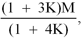
[0024] A set of voltages in proportion to the above derived values, it is observed, first generates pressures that are normalised when K is in a range close to KOPT = 1/2 if the printhead is an array of shared wall actuators.
[0025] The actuation rules, when selected odd channels in the array are actuated is that
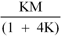
1. The actuated channels in the odd group have a voltage M applied.
2. The non-actuated channels in the odd group have voltage
applied.
3. The even channels adjacent two actuated channels have voltage zero applied.
4. The even channels adjacent to one actuated channel have voltage
applied. (1
5. The remaining even channels adjacent to no actuated channels have voltage
applied.
[0026] However, in a region of the array remote from actuated channels, the applied voltage to both odd and even channels can fall towards zero with a small error.
[0027] In document EP-A-0 422 870 there is disclosed a method of operating the multi-channel array droplet deposition apparatus by applying sequences of pulses to selected channels of the array at or near the longitudinal acoustic resonant frequency of the channels. The number of pulses in each sequence determines the number of droplets ejected from the nozzles and deposited for printing.
[0028] In one preferred method of operation, when a group of adjacent channels is selected for operation, pressure is applied to the odd numbered (say) channels in the group as a result of actuation of the channels during one half of the resonance cycle and is then applied to the even numbered channels of the group during the following half of the resonant cycle, so operating adjacent channels in alternate half phases of the resonant cycle.
[0029] Consider, for example, a series of eleven channels numbered 1 to 11 of which five channels numbered 4 to 8 are subjected to resonant operation. If the walls between the channels have zero compliance, then the pattern of actuation and the pressures to effect actuation in the channels described take the form
| Channel number | 1 | 2 | 3 | 4 | 5 | 6 | 7 | 8 | 9 | 10 | 11 |
| Odd number of channels actuated for drop ejection in one cycle | * | * | * | * | * | ||||||
| Pressure in first half cycle | 0 | 0 | - |
+P | -P | +P | -P | +P | - |
0 | 0 |
| Pressure in second half cycle | 0 | 0 | + |
-P | +P | -P | +P | -P | + |
0 | 0 |
is below the threshold. Although the resonant pressures in the channels selected for drop ejection are denoted as +P and -P it will be evident that if the mean pressure is somewhat different from zero to promote ink replenishment, the basic principles of operation are not essentially modified.
[0030] In an array in which the channel walls have a compliance ratio K (which is greater than K=0, suitably 0.2 <K<2) then voltages which compensate for the wall compliance need to be applied. Such voltages generate the above pressure distribution. Also preferably the voltages are unipolar to simplify the drive transistors. Using the principles already described, a voltage array which compensates for the wall compliance takes the form for the sequence of five actuated channels as follows:
[0031] In the above table of voltages, M represents the scaling factor on voltage level required to eject drops when all the channels in a group of adjacent channels are selected for operation. Accordingly, the five channels 4 to 8 which are selected have voltages 0 and M in time in alternative phases and also alternate spatially to generate pressures +P and -P. Channels 3 and 9 have only one neighbouring actuated channel, so that they are subjected to voltages
and
so generating alternating pressures -
and
.
However, channels 1, 2 and 3 and likewise 9, 10 and 11 have voltages moving in unison, so that there is no actuating wall displacement thereof except for the values sufficient to compensate for crosstalk in these channels and thus no pressure is generated.
[0032] It will be seen that the voltages in the channels which are not actuated nevertheless are subjected to oscillatory voltages. Since, however, neighbouring channels have the same polarity of voltage at any time, these signals do not generate pressure.
[0033] In the case of an even numbered group of actuated channels, it is found that the voltages applied in the non-actuated channels are again subjected to alternating voltages. In this case, however, correct compensation is only obtained when the alternating voltages on either side of the group are of opposite phase. The pressures for an even numbered group of actuated channels takes the form:
| Channel number | 1 | 2 | 3 | 4 | 5 | 6 | 7 | 8 | 9 | 10 | 11 | 12 |
| Even number of channels actuated for drop ejection in one cycle | * | * | * | * | * | * | ||||||
| Pressure in first half cycle | 0 | 0 | - |
+P | -P | +P | -P | +P | -P | + |
0 | 0 |
| Pressure in second half cycle | 0 | 0 | + |
-P | +P | -P | +P | -P | +P | - |
0 | 0 |
[0034] Again it is the non-printing channels that are subjected to compensated voltages, but for the even sequence of printed channels the voltages, which are applied in unison and, therefore, generate no pressures, are in opposite phase on either side to provide the correct pressure compensation.
[0035] The accompanying analysis shows that similar correction applies to piezo-electric roof mode actuation. However, in this case actuation is not limited to odd and even numbered channels in alternate cycles, but all channels may be actuated at the same time. Such an array is described in United States Patents 4,584,590 and 4,825,227.
[0036] In this instance also the optimum actuation voltage does not depend on the inter channel compliance ratio K consequently the normalisation rules are different. For example, if channels 3, 6, 7 and 8 are actuated
| Channel number | 1 | 2 | 3 | 4 | 5 | 6 | 7 | 8 | 9 | 10 | 11 |
| Channel actuated | * | * | * | * | |||||||
| Channel pressure | 0 | 0 | P | 0 | 0 | P | P | P | 0 | 0 | 0 |
| Channel voltage | 0 | -K | (1+2K) | -K | -K | (1+K) | 1 | (1+K) | -K | 0 | 0 |
[0037] Since negative applied voltages are not desirable the set of voltages above may be written, as K varies, by adding any suitable voltage corrections to each channel, such as 2K.
Channel voltage 2K, K, (1+4K), K, K, (1+3K), (1+2K), (1+3K), K, 2K, 2K
Normally K will be small so that the added voltage 2K will not cause drop ejection. The values can be normalised to set the voltage applied to a single isolated channel (such as channel 3) to unity.
Accordingly for an array capable of actuating any channel, where the compliance ratio defining crosstalk is K
[0038] The same general rules apply to other types of array printheads, such as bubble jet, allowing for the fact that the pressure and voltage of actuation are in this case no longer linear.
[0039] Accordingly, it will be seen that a scheme of actuation exists in which inter channel compliance in the array does not result in inter channel crosstalk.
[0040] There follows a note on the mathematics from which the desired pressure pattern for a shared wall array is developed.
SHARED WALL INK JET PRINTHEAD (as described in U.S. Patent No. 4,887,100)
[0041] The array is modelled as a number of identical two-dimensional channels of width b containing ink. The walls separating the channels are compliant, and a pressure difference across the walls will cause a lateral deflection. Wall inertia can be neglected as the resonant frequency of wall vibration is much higher than the frequencies associated with drop ejection. Since the wall compliance arises primarily from the built-in conditions at the top and bottom of the walls, also ignored is any stiffness associated with longitudinal flexure and wall compliance is represented by a simple transverse compliance k.
[0042] The channel walls are of a piezo-electric material, and applying an electric field across the walls has the effect of altering their equilibrium position. The displacement of the equilibrium position of the wall is proportional to the applied voltage difference, in which the activity depends on the properties of the material and on the wall geometry.
[0043] Under the conditions set forth there can now be obtained the following system of equations:
These can be cast in matrix form as follows:
where
is the ratio between the compliance of the wall and the effective compliance of the ink in the channel, V is the vector of actuation voltages, P is the vector of channel pressures, and A is the second-difference matrix:
Here there has been chosen the top-left hand corner entry of A to correspond to a rigid wall at the end of the array. Other end conditions are possible, and only change the details of the analysis.
[0044] The matrix equation enables the pressure field generated by a given applied voltage pattern to be computed, and has a number of interesting features. The first is that a voltage pattern which is proportional to any eigenvector of A will generate a pressure pattern corresponding to the same eigenvector. The second feature is that the matrix A is singular. This is an indication of the fact that it is not possible to change the average pressure in a shared-wall array by shear mode actuation.
Symbols
[0046]
- A
- second difference matrix
- b
- channel width
- co
- speed of sound in the ink alone
- I
- identity matrix
- k
- transverse wall compliance
- Po
- channel pressure in response to actuation
- Poi-1,Poi,Poi+1
- pressure in i-1, 1 and i+1 channels
- V
- actuation voltage
- Vi-1,Vi,Vi+1
- voltage applied to electrodes in i-1, i, and i+1 channels
- α
- activity of a wall, pressure per voltage difference applied
- K
- compliance ratio
- ρo
- ink density.
- a
- vector of the logic state of the actuated lines.
CANCELLATION OF CROSSTALK
[0047] Cancellation of crosstalk in a shared wall actuator can be effected by solving equation (2) to determine the drive voltage pattern needed to generate the required channel pressures. The figure below shows an example firing pattern and the corresponding required pressure pattern.
Because the matrix equation is singular there is no unique solution - any uniform voltage can be added to the applied pattern without affecting the pressures generated. This has the consequence that the need for negative drive voltages in a compensation scheme can be eliminated, which is of considerable benefit in simplifying the electronic design.
[0048] The above pressure pattern can be written
where a is the vector of the logic state of actuated lines. Substituting this into the matrix equation, we obtain:
If we "cancel" A from both sides, we get:
which looks like this:
[0049] This solution can be substituted into the matrix equation and checked that the right answer is obtained. Now, to remove the negative voltages 2K is added to each coefficient.
[0050] The compensation scheme with no negative voltages is described as follows. A voltage of (1+4K)Vo is applied to the lines which are fired, where Vo is the voltage that would generate the necessary actuation pressure in the absence of actuator compliance. Voltage 2KVo is applied to lines which are not adjacent to the actuated lines, the difference (1+2K)Vo representing the increased voltage necessary to overcome pressure loss due to compliance effects.
1. The method of operating a multi-channel array pulsed droplet deposition apparatus
comprising an array of parallel channels, channel walls each separating one channel
of the array from an adjacent channel in the array, the channel walls having a wall
compliance, respective nozzles communicating with said channels for ejection of droplets
of liquid from the channels, droplet liquid supply means connected with the channels
for the supply to the channels of droplet liquid having a liquid compliance and electrically
actuable means located in relation to said channels for imparting energy pulses to
droplet liquid in the channels so that droplets are ejected from the nozzles of selected
ones of the channels, characterised by comprising the steps of applying through said
electrically actuable means energy pulses of a first amplitude to the droplet liquid
in selected ones of the channels of the array and applying through said electrically
actuable means energy pulses of a second amplitude to the liquid in at least some
others of the channels in the array in the vicinity of said selected channels said
first and second amplitudes being dependent upon a ratio of said wall compliance and
said liquid compliance, to produce a pressure distribution in the channels of the
array which effects droplet ejection from only said selected channels and is substantially
free from pressure crosstalk between said selected channels or between said selected
channels and other channels of the array.
2. The method of operating a multi-channel array pulsed droplet deposition apparatus
comprising an array of parallel channels, channel walls each separating one channel
of the array from an adjacent channel in the array, the channel walls having a wall
compliance, respective nozzles communicating with said channels for ejection of droplets
of liquid from the channels, droplet liquid supply means connected with the channels
for the supply to the channels of droplet liquid having a liquid compliance and electrically
actuable means located in relation to said channels for imparting energy pulses to
droplet liquid in the channels so that droplets are ejected from the nozzles at selected
ones of the channels characterised by comprising the steps of applying through said
electrically actuable means energy pulses of a first amplitude to the droplet liquid
in selected ones of the channels of the array and applying through said electrically
actuable means energy pulses of a second amplitude to the liquid in at least some
others of the channels in the array in the vicinity of said selected channels, said
first and second amplitudes being dependent upon a ratio of said wall compliance and
said liquid compliance, to develop a distribution of potential energy stored in the
channels to which said pulses are applied which effects droplet ejection only from
said selected channels at substantially uniform momentum between said selected channels.
3. The method claimed in Claim 1 or Claim 2, wherein the step of applying energy pulses
through said electrically actuable means comprises applying unipolar voltages for
each of said channels.
4. The method claimed in Claim 3, characterised by forming said unipolar voltages by
adding a constant voltage to each of the channel voltages.
5. The method claimed in any preceding claim and in which channel walls of the droplet
deposition apparatus are compliant and each are provided with said electrically actuable
means so that actuation of opposed side walls by said electrically actuable means
effects droplet expulsion from a channel therebetween, the channels being divided
in two groups of which the channels of one group alternate with those of the other
group, characterised by employing a scheme of voltage actuation to reduce crosstalk
that generates array pressures at least in a region of the array including actuated
channels, as follows,
where P represents pressure applied to an actuated channel.
| Type of Channel | Actuated Neighbours | Applied Pressure |
| Actuated Group | ||
| Actuated | - | P |
| Non-Actuated | 0 | |
| Non-Actuated Group | 2 | -P |
| 1 | -P/2 | |
| 1 | 0 |
6. The method claimed in Claim 4, characterised by employing a scheme of voltage actuation,
as follows:
where K equals said ratio of the compliance of the channel walls to the compliance
of the droplet deposition liquid.
| Type of Channel | Actuated Neighbour | Proportionality of Applied Voltage |
| Actuated Group | ||
| Actuated | - | 1 + 2K |
| Non-Actuated | - | 0 |
| Non-Actuated Group | 2 | -2K |
| 1 | -K | |
| 0 | 0 |
7. The method claimed in claim 6, characterised by adding a voltage of magnitude proportional
to +2K to each of the voltages applied to said selected channels and said channels
in the vicinity of said selected channels to provide said unipolar voltages.
8. The method claimed in Claim 6, characterised by further scaling the voltages applied
to said selected channels and said channels in the vicinity of said selected channels
by a constant of proportionality.
9. The method claimed in Claim 8, characterised in that said constant of proportionality
includes 1/(1+4K).
10. The method claimed in Claim 7, characterised by further scaling the voltages applied
to said selected channels and said channels in the vicinity of said selected channels
by a constant of proportionality.
11. The method claimed in Claim 10, characterised in that said constant of porportionality
includes 1/(1+4K).
12. The method claimed in any one of Claims 6 to 11, characterised by further scaling
the voltages applied to said selected channels and said channels in the vicinity of
said selected channels by a constant of proportionality which includes M, where
13. The method claimed in any one of Claims 6 to 11, characterised by further scaling
the voltages applied to said selected channels and said channels in the vicinity of
said selected channels by a constant of proportionality which includes M, where

and KOPT an optimum value of K which occurs when the voltages applied to said selected channels to effect droplet ejection therefrom are a minimum.
and KOPT an optimum value of K which occurs when the voltages applied to said selected channels to effect droplet ejection therefrom are a minimum.
14. The method claimed in Claim 13, characterised in that KOPT is chosen to equal 0.5 when said selected channels comprise an entire group of alternate
channels of the array.
15. The method claimed in any one of Claims 1 to 4, and in which the channel array comprises
open topped channels formed in a base from which compliant inactive channel dividing
side walls are upstanding, the open topped channels being closed by an active wall
means actuable by said electrically actuable means, characterised by applying actuating
voltages using said electrically actuable means .
16. The method claimed in Claim 15, characterised by rendering unipolar said actuating
voltages by adding to each of said actuating voltages a voltage proportional to 2K
where K is said compliance ratio.
17. The method claimed in Claim 16, characterised by further scaling the actuating voltages
by a constant of proportionality.
18. The method claimed in Claim 17, characterised by employing a scheme of voltage actuation,
as follows:-
19. The method of operating a multi-channel array droplet deposition apparatus comprising
an array of parallel channels uniformly spaced by channel separating side walls, said
side walls having a wall compliance, respective nozzles communicating with said channels
for ejection of droplets of liquid from the channels, droplet liquid supply means
connected with the channels for the supply to the channels of droplet liquid having
a liquid compliance and electrically actuable means located in relation to said channels
for imparting energy pulses to droplet liquid in the channels to effect droplet ejection
from the channels, characterised by comprising the steps of selecting a group of successive
ones of the channels of the array and applying to the channels of said group through
said electrically actuable means energy pulses of a first amplitude to effect in a
first half cycle of operation droplet ejection from alternate ones of the channels
of the selected group and in a second half cycle of operation droplet ejection from
remaining ones of the channels of the group; and applying to channels at opposite
sides of said selected group of channels energy pulses of a second amplitude, said
first and second amplitudes being so dependent on a ratio of said wall compliance
and saidliquid compliance as to compensate for pressure cross-talk between channels
of the selected group or between said selected group of channels and other channels
of the array.
20. The method claimed in Claim 19, wherein the step of imparting energy pulses to liquid
in the channels comprises applying channel voltages for each of said channels.
21. The method claimed in Claim 20, wherein each channel voltage has a first voltage level
in said first half cycle of operation and a second voltage level in said second half
cycle of operation.
22. The method claimed in Claim 21, in which said selected group of channels comprises
an odd number of channels, wherein said first voltage level for odd numbered channels
of the selected group is proportional to M, and for even numbered channels of the
selected group is zero, wherein said first voltage level for respective channels on
opposite sides of and adjacent said selected channel group is proportional to

and for respective channels on opposite sides of said selected channel group one, two or more channels removed from said channel group is proportional to
and wherein said second voltage level for even numbered channels of the selected group is proportional to M, and for odd numbered channels of said selected group is zero, and wherein said second voltage level for respective channels on opposite sides of and adjacent said selected channel group, is proportional to

and for respective channels on opposite sides of said selected channel group one, two or more channels removed from said channel group is proportional to

where M is a scaling factor whose value is
and K is said compliance ratio.
and for respective channels on opposite sides of said selected channel group one, two or more channels removed from said channel group is proportional to
and wherein said second voltage level for even numbered channels of the selected group is proportional to M, and for odd numbered channels of said selected group is zero, and wherein said second voltage level for respective channels on opposite sides of and adjacent said selected channel group, is proportional to
and for respective channels on opposite sides of said selected channel group one, two or more channels removed from said channel group is proportional to
where M is a scaling factor whose value is
and K is said compliance ratio.
23. The method claimed in Claim 21, in which said selected group of channels comprises
an odd number of channels, wherein said first voltage level for odd numbered channels
of the selected group is proportional to M, and for even numbered channels of the
selected group is zero, wherein said first voltage level for respective channels on
opposite sides of and adjacent said selected channel group is proportional to

and for respective channels on opposite sides of said selected channel group one, two or more channels removed from said channel group is proportional to

and wherein said second voltage level for even numbered channels of the selected group is proportional to M, and for odd numbered channels of said selected group is zero, and wherein said second voltage level for respective channels on opposite sides of and adjacent said selected channel group, is proportional to

and for respective channels on opposite sides of said selected channel group one, two or more channels removed from said channel group like voltages proportional to
where M is a scaling factor whose value is

and where K is said compliance ratio and KOPT is the optimum value of K and is given by
.
and for respective channels on opposite sides of said selected channel group one, two or more channels removed from said channel group is proportional to
and wherein said second voltage level for even numbered channels of the selected group is proportional to M, and for odd numbered channels of said selected group is zero, and wherein said second voltage level for respective channels on opposite sides of and adjacent said selected channel group, is proportional to
and for respective channels on opposite sides of said selected channel group one, two or more channels removed from said channel group like voltages proportional to
where M is a scaling factor whose value is
and where K is said compliance ratio and KOPT is the optimum value of K and is given by
.
24. The method of Claim 21, in which said selected group of channels comprises an even
number of channels, wherein said first voltage level for even numbered channels of
the selected group is proportional to M, and for odd numbered channels of the selected
group is zero, wherein said first voltage level for the channel adjacent said channel
group on the side of the first channel of said group is proportional to

and for the channel adjacent said channel group on the side of the last channel thereof is proportional to

for each of the channels spaced respectively by one, two or more channels from the first channel of said channel group is proportional to

and for each of said channels spaced by one, two or more channels from the last channel of said channel group is proportional to

and wherein said second voltage level for odd numbered channels of the selected group is proportional to M and for even numbered channels of said selected channel group is zero, and wherein said second voltage level for the channel adjacent said channel group on the side of the first channel thereof is proportional to

for the channel adjacent said channel group on the side of the last channel thereof is proportional to

for each of the channels spaced respectively by one, two or more channels from said last channel of said group is proportional to

and for each of the channels spaced respectively by one, two or more channels from said first channel of said channel group, is proportional to
where M is a scaling factor whose value is

and K is said compliance ratio.
and for the channel adjacent said channel group on the side of the last channel thereof is proportional to
for each of the channels spaced respectively by one, two or more channels from the first channel of said channel group is proportional to
and for each of said channels spaced by one, two or more channels from the last channel of said channel group is proportional to
and wherein said second voltage level for odd numbered channels of the selected group is proportional to M and for even numbered channels of said selected channel group is zero, and wherein said second voltage level for the channel adjacent said channel group on the side of the first channel thereof is proportional to
for the channel adjacent said channel group on the side of the last channel thereof is proportional to
for each of the channels spaced respectively by one, two or more channels from said last channel of said group is proportional to
and for each of the channels spaced respectively by one, two or more channels from said first channel of said channel group, is proportional to
where M is a scaling factor whose value is
and K is said compliance ratio.
25. The method of Claim 21, in which said selected group of channels comprises an even
number of channels, wherein said first voltage level for even numbered channels of
the selected group is proportional to M, and for odd numbered channels of the selected
group is zero, wherein said first voltage level for the channel adjacent said channel
group on the side of the first channel of said group is proportional to

for the channel adjacent said channel group on the side of the last channel thereof is proportional to
for each of the channels spaced respectively by one, two or more channels from the first channel of said channel group is proportional to
and for each of said channels spaced by one, two or more channels from the last channel of said channel group is proportional to

and wherein said second voltage level for odd numbered channels of the selected group is proportional to M and for even numbered channels of said selected channel group is zero and wherein said second level for the channel adjacent said channel group on the side of the first channel thereof is proportional to

for the channel adjacent said channel group on the side of the last channel thereof is proportional to
for each of the channels spaced respectively by one, two or more channels from said last channel of said group is proportional to

and for each of the channels spaced respectively by one, two or more channels from said first channel of said channel group is proportional to

where M is a scaling factor whose value is

and where K is said compliance ratio and KOPT is the optimum value of K and is given by
.
for the channel adjacent said channel group on the side of the last channel thereof is proportional to
for each of the channels spaced respectively by one, two or more channels from the first channel of said channel group is proportional to
and for each of said channels spaced by one, two or more channels from the last channel of said channel group is proportional to
and wherein said second voltage level for odd numbered channels of the selected group is proportional to M and for even numbered channels of said selected channel group is zero and wherein said second level for the channel adjacent said channel group on the side of the first channel thereof is proportional to
for the channel adjacent said channel group on the side of the last channel thereof is proportional to
for each of the channels spaced respectively by one, two or more channels from said last channel of said group is proportional to
and for each of the channels spaced respectively by one, two or more channels from said first channel of said channel group is proportional to
where M is a scaling factor whose value is
and where K is said compliance ratio and KOPT is the optimum value of K and is given by
.
1. Verfahren zum Betreiben eines Vielkanalfeld-Gerätes zum gepulsten Niederschlag von
Tröpfchen mit einem Feld paralleler Kanäle, mit Kanalwänden, die jeweils einen Kanal
des Feldes von einem benachbarten Kanal in dem Feld trennen, wobei die Kanalwände
eine Wand-Nachgiebigkeit aufweisen, mit jeweiligen Düsen, die mit den Kanälen zur
Abgabe bzw. zum Ausspritzen von Flüssigkeitströpfchen aus den Kanälen in Verbindung
stehen, mit einer Vorratseinrichtung für Tröpfchenflüssigkeit, die mit den Kanälen
verbunden ist, um die Kanäle mit Tröpfchenflüssigkeit zu versorgen, die eine Flüssigkeits-Nachgiebigkeit
aufweist, und mit einer elektrisch betätigbaren Einrichtung, die sich in Beziehung
zu den Kanälen befindet, um Energiepulse an die Tröpfchenflüssigkeit in den Kanälen
anzulegen, so daß Tröpfchen von den Düsen aus gewählten Kanälen ausgespritzt werden,
gekennzeichnet durch die Schritte, wonach durch die elektrisch betätigbare Einrichtung Energiepulse
einer ersten Amplitude an die Tröpfchenflüssigkeit in gewählten Kanälen des Feldes
angelegt werden und durch die elektrisch betätigbare Einrichtung Energiepulse einer
zweiten Amplitude an die Flüssigkeit in wenigstens einigen anderen der Kanäle in dem
Feld in der Nähe der gewählten Kanäle angelegt werden, wobei die erste und zweite
Amplitude von einem Verhältnis der Wand-Nachgiebigkeit und der Flüssigkeits-Nachgiebigkeit
abhängt, um eine Druckverteilung in den Kanälen des Feldes zu erzeugen, die das Tröpfchenausspritzen
aus nur den gewählten Kanälen bewirkt und im wesentlichen frei von einem Druck-Übersprechen
zwischen den gewählten Kanälen oder zwischen den gewählten Kanälen und anderen Kanälen
des Feldes ist.
2. Verfahren zum Betreiben eines Vielkanalfeld-Gerätes zum gepulsten Niederschlag von
Tröpfchen mit einem Feld paralleler Kanäle, mit Kanalwänden, die jeweils einen Kanal
des Feldes von einem benachbarten Kanal in dem Feld trennen, wobei die Kanalwände
eine Wand-Nachgiebigkeit aufweisen, mit jeweiligen Düsen, die mit den Kanälen zur
Abgabe bzw. zum Ausspritzen von Flüssigkeitströpfchen aus den Kanälen in Verbindung
stehen, mit einer Vorratseinrichtung für Tröpfchenflüssigkeit, die mit den Kanälen
verbunden ist, um die Kanäle mit Tröpfchenflüssigkeit zu versorgen, die eine Flüssigkeits-Nachgiebigkeit
aufweist, und mit einer elektrisch betätigbaren Einrichtung, die sich in bezug zu
den Kanälen befindet, um Energiepulse an die Tröpfchenflüssigkeit in den Kanälen anzulegen,
so daß Tröpfchen von den Düsen bei gewählten Kanälen ausgespritzt werden, gekennzeichnet durch die Schritte, wonach durch die elektrisch betätigbare Einrichtung Energiepulse
einer ersten Amplitude an die Tröpfchenflüssigkeit in gewählten Kanälen des Feldes
angelegt werden und durch die elektrisch betätigbare Einrichtung Energiepulse einer
zweiten Amplitude an die Flüssigkeit in wenigstens einigen anderen der Kanäle in dem
Feld in der Nähe der gewählten Kanäle angelegt werden, wobei die erste und zweite
Amplitude von einem Verhältnis der Wand-Nachgiebigkeit und der Flüssigkeits-Nachgiebigkeit
abhängt, um eine Verteilung der potentiellen Energie zu entwickeln, die in den Kanälen
gespeichert ist, an die die Pulse angelegt werden, und die ein Tröpfchenausspritzen
nur von den gewählten Kanälen bei im wesentlichen gleichförmiger Bewegungsenergie
unter den gewählten Kanälen bewirkt.
3. Verfahren, das in Anspruch 1 oder Anspruch 2 beansprucht ist, bei welchem der Schritt
des Anlegens der Energiepulse durch die elektrisch betätigbare Einrichtung das Anlegen
einpoliger Spannungen für jeden der Kanäle umfaßt.
4. Verfahren, das in Anspruch 3 beansprucht ist, dadurch gekennzeichnet, daß die einpoligen Spannungen ausgebildet werden, indem eine konstante Spannung
zu jedem der Kanalspannungen addiert wird.
5. Verfahren, das in irgendeinem vorhergehenden Anspruch beansprucht ist und bei welchem
die Kanalwände des Geräts zum Tröpfchenniederschlag nachgiebig sind und jede mit der
elektrisch betätigbaren Einrichtung versehen ist, so daß die Betätigung gegenüberliegender
Seitenwände durch die elektrisch betätigbare Einrichtung Tröpfchenausstoß aus einem
Kanal dazwischen bewirkt, wobei die Kanäle in zwei Gruppen aufgeteilt sind, von denen
die Kanäle der einen Gruppe mit denen der anderen Gruppe alternieren, dadurch gekennzeichnet, daß ein Spannungsbetätigungsschema verwendet wird, um das Übersprechen zu verringern,
das Felddrücke wenigstens in einem Bereich des Feldes erzeugt, der betätigte Kanäle
beinhaltet, und zwar wie folgt:
wobei P den Druck darstellt, der an einen betätigten Kanal angelegt wird.
| Typ des Kanals | betätigter Nachbar | angelegter Druck |
| betätigte Gruppe | ||
| betätigt | - | P |
| nicht-betätigt | 0 | |
| nicht-betätigte Gruppe | 2 | -P |
| 1 | -P/2 | |
| 0 | 0 |
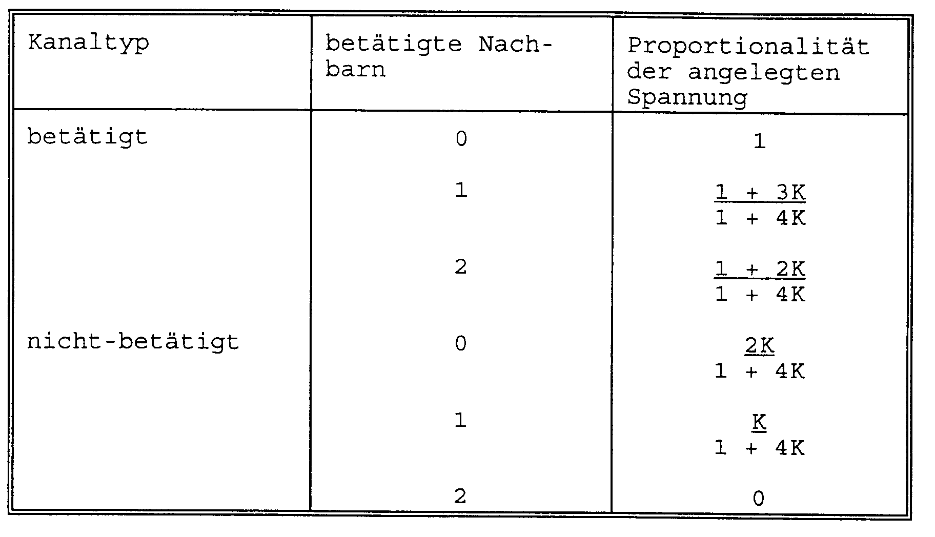
6. Verfahren, das in Anspruch 4 beansprucht ist, dadurch gekennzeichnet, daß ein Spannungsbetätigungsschema wie folgt verwendet wird:
wobei K gleich dem Verhältnis der Nachgiebigkeit der Kanalwände zu der Nachgiebigkeit
der Tröpfchen-Niederschlagsflüssigkeit ist.
| Typ des Kanals | betätigter Nachbar | Proportionalität der angelegten Spannung |
| betätigte Gruppe | ||
| betätigt | - | 1 + 2K |
| nicht-betätigt | - | 0 |
| nicht-betätigte Gruppe | 2 | -2K |
| 1 | -K | |
| 0 | 0 |
7. Verfahren, das in Anspruch 6 beansprucht ist, dadurch gekennzeichnet, daß eine Spannung einer Stärke addiert wird, die proportional zu +2K zu jeder der
Spannungen ist, die an die gewählten Kanäle und die Kanäle in der unmittelbaren Umgebung
der gewählten Kanäle angelegt werden, um einpolige Spannungen bereitzustellen.
8. Verfahren, das in Anspruch 6 beansprucht ist, dadurch gekennzeichnet, daß weiterhin die Spannungen, die an die gewählten Kanäle und die Kanäle in der
unmittelbaren Umgebung der gewählten Kanäle angelegt werden, durch eine Proportionalitätskonstante
skaliert werden.
9. Verfahren, das in Anspruch 8 beansprucht ist, dadurch gekennzeichnet, daß die Proportionalitätskonstante 1/(1+4K) beinhaltet.
10. Verfahren, das in Anspruch 7 beansprucht ist, dadurch gekennzeichnet, daß weiter die Spannungen, die an den gewählten Kanälen und den Kanälen in der unmittelbaren
Nachbarschaft der gewählten Kanäle angelegt werden, durch eine Proportionalitätskonstante
skaliert werden.
11. Verfahren, das in Anspruch 10 beansprucht ist, dadurch gekennzeichnet, daß die Proportionalitätskonstante 1/(1+4K) beinhaltet.
12. Verfahren, das in irgendeinem der Ansprüche 6 bis 11 beansprucht ist, dadurch gekennzeichnet, daß weiter die Spannungen, die an den gewählten Kanälen und an den Kanälen in der
unmittelbaren Umgebung der gewählten Kanäle angelegt werden, durch eine Proportionalitätskonstante
skaliert werden, die M beinhaltet, wobei
13. Verfahren, das in irgendeinem der Ansprüche 6 bis 11 beansprucht ist, dadurch gekennzeichnet, daß weiter die Spannungen, die an die gewählten Kanäle und die Kanäle in der unmittelbaren
Nachbarschaft der gewählten Kanäle angelegt werden, durch eine Proportionalitätskonstante
skaliert werden, die M beinhaltet, wobei

und KOPT ein optimaler Wert von K ist, der auftritt, wenn die Spannungen, die an die gewählten Kanäle angelegt werden, um eine Tröpfchenausspritzung daraus zu bewirken, minimal sind.
und KOPT ein optimaler Wert von K ist, der auftritt, wenn die Spannungen, die an die gewählten Kanäle angelegt werden, um eine Tröpfchenausspritzung daraus zu bewirken, minimal sind.
14. Verfahren, das im Anspruch 13 beansprucht ist, dadurch gekennzeichnet, daß KOPT so gewählt wird, daß es gleich 0,5 ist, wenn die gewählten Kanäle eine ganze Gruppe
von alternierenden Kanälen des Feldes aufweisen.
15. Verfahren, das in irgendeinem der Ansprüche 1 bis 4 beansprucht ist und bei welchem
das Kanalfeld oben mit einem offenen Ende versehene Kanäle aufweist, die in einem
Grundteil ausgebildet sind, von dem nachgiebige inaktive Seitenwände, die Kanäle trennen,
nach oben wegstehen, wobei die oben mit einem offenen Ende versehenen Kanäle durch
eine aktive Wandeinrichtung abgeschlossen werden, die durch die elektrisch betätigbare
Einrichtung betätigbar ist, dadurch gekennzeichnet, daß Betätigungsspannungen angelegt werden, die die elektrisch betätigbare Einrichtung
verwenden.
16. Verfahren, das in Anspruch 15 beansprucht ist, dadurch gekennzeichnet, daß die Betätigungsspannungen einpolig gemacht werden, indem zu jedem der Betätigungsspannungen
eine Spannung addiert wird, die proportional zu 2K ist, wobei K das Nachgiebigkeitsverhältnis
ist.
17. Verfahren, das in Anspruch 16 beansprucht ist, dadurch gekennzeichnet, daß die Betätigungsspannungen weiter durch eine Proportionalitätskonstante skaliert
werden.
18. Verfahren, das in Anspruch 17 beansprucht ist, dadurch gekennzeichnet, daß ein Schema der Spannungsbetätigung wie folgt verwendet wird:
19. Verfahren zum Betreiben eines Vielkanalfeld-Gerätes zum Niederschlagen von Tropfen
mit einem Feld paralleler Kanäle, die gleichförmig durch kanaltrennende Seitenwände
beabstandet sind, wobei die Seitenwände eine Wand-Nachgiebigkeit aufweisen, mit jeweiligen
Düsen, die mit den Kanälen zum Ausspritzen von Flüssigkeitstropfen aus den Kanälen
verbunden sind, mit einer Vorratseinrichtung für Tröpfchenflüssigkeit, die mit den
Kanälen für die Versorgung der Kanäle mit Tröpfchenflüssigkeit verbunden sind, die
eine Flüssigkeits-Nachgiebigkeit aufweist, und mit einer elektrisch betätigbaren Einrichtung,
die sich in Beziehung zu den Kanälen befindet, um Energiepulse an die Tröpfchenflüssigkeit
in den Kanälen anzulegen, um eine Tropfenabgabe bzw. ein Ausspritzen von Tropfen aus
den Kanälen zu bewirken, dadurch gekennzeichnet, daß es die Schritte aufweist, wonach eine Gruppe aufeinanderfolgender Kanäle des
Feldes gewählt wird und an die Kanäle der Gruppe durch die elektrisch betätigbare
Einrichtung Energiepulse einer ersten Amplitude angelegt werden, um in einem ersten
halben Betriebszyklus eine Tropfenabgabe aus alternierenden Kanälen der gewählten
Gruppe und in einem zweiten halben Betriebszyklus Tropfenabgabe aus den verbleibenden
Kanälen der Gruppe zu bewirken; und wonach an die Kanäle bei gegenüberliegenden Seiten
der gewählten Gruppe von Kanälen Energiepulse einer zweiten Amplitude angelegt werden,
wobei die ersten und zweiten Amplituden so von einem Verhältnis der Wand-Nachgiebigkeit
und der Flüssigkeitsnachgiebigkeit abhängen, um ein Druckübersprechen zwischen den
Kanälen der gewählten Gruppe oder zwischen der gewählten Gruppe von Kanälen und anderen
Kanälen des Feldes auszugleichen.
20. Verfahren, das in Anspruch 19 beansprucht ist, bei welchem der Schritt des Anlegens
von Energiepulsen an die Flüssigkeit in den Kanälen das Anlegen von Kanalspannungen
für jeden der Kanäle aufweist.
21. Verfahren, das in Anspruch 20 beansprucht ist, bei welchem jede Kanalspannung einen
ersten Spannungspegel in dem ersten halben Betriebszyklus und einen zweiten Spannungspegel
in dem zweiten halben Betriebszyklus aufweist.
22. Verfahren, das in Anspruch 21 beansprucht ist, bei welchem die gewählte Gruppe von
Kanälen eine ungerade Zahl von Kanälen aufweist, bei welchem der erste Spannungspegel
für ungeradzahlige Kanäle der gewählten Gruppe proportional zu M ist und für geradzahlige
Kanäle der gewählten Gruppe Null ist, bei welchem der erste Spannungspegel für jeweilige
Kanäle auf gegenüberliegenden Seiten von und benachbart der gewählten Kanalgruppe
proportional zu

ist und für jeweilige Kanäle auf gegenüberliegenden Seiten der gewählten Kanalgruppe einen, zwei oder mehr Kanäle von der Kanalgruppe entfernt proportional zu
ist und bei welchem der zweite Spannungspegel für geradzahlige Kanäle der gewählten Gruppe proportional zu M ist und für ungeradzahlige Kanäle der gewählten Gruppe Null ist und bei welchem der zweite Spannungspegel für jeweilige Kanäle auf gegenüberliegenden Seiten von und benachbart der gewählten Kanalgruppe proportional zu

und für jeweilige Kanäle auf gegenüberliegenden Seiten der gewählten Kanalgruppe einen, zwei oder mehr Kanäle entfernt von der Kanalgruppe proportional zu

ist, wobei M ein Skalierungsfaktor ist, dessen Wert
und K das Nachgiebigkeitsverhältnis ist.
ist und für jeweilige Kanäle auf gegenüberliegenden Seiten der gewählten Kanalgruppe einen, zwei oder mehr Kanäle von der Kanalgruppe entfernt proportional zu
ist und bei welchem der zweite Spannungspegel für geradzahlige Kanäle der gewählten Gruppe proportional zu M ist und für ungeradzahlige Kanäle der gewählten Gruppe Null ist und bei welchem der zweite Spannungspegel für jeweilige Kanäle auf gegenüberliegenden Seiten von und benachbart der gewählten Kanalgruppe proportional zu
und für jeweilige Kanäle auf gegenüberliegenden Seiten der gewählten Kanalgruppe einen, zwei oder mehr Kanäle entfernt von der Kanalgruppe proportional zu
ist, wobei M ein Skalierungsfaktor ist, dessen Wert
und K das Nachgiebigkeitsverhältnis ist.
23. Verfahren, das in Anspruch 21 beansprucht ist, bei welchem die gewählte Gruppe von
Kanälen eine ungerade Anzahl von Kanälen aufweist, bei welchem der erste Spannungspegel
für ungeradzahlige Kanäle der gewählten Gruppe proportional zu M ist und für geradzahlige
Kanäle der gewählten Gruppe Null ist, bei welchen der erste Spannungspegel für jeweilige
Kanäle auf gegenüberliegenden Seiten von und benachbart der gewählten Kanalgruppe
proportional zu
ist und für jeweilige Kanäle auf gegenüberliegenden Seiten der gewählten Kanalgruppe einen, zwei oder mehr Kanäle entfernt von der Kanalgruppe proportional zu

ist und bei welchem der zweite Spannungspegel für geradzahlige Kanäle der gewählten Gruppe proportional zu M ist und für ungeradzahlige Kanäle der gewählten Gruppe Null ist, und bei welchem der zweite Spannungspegel für jeweilige Kanäle auf gegenüberliegenden Seiten von und benachbart der gewählten Kanalgruppe proportional zu

ist und für jeweilige Kanäle auf gegenüberliegenden Seiten der gewählten Kanalgruppe einen, zwei oder mehr Kanäle entfernt von der Kanalgruppe ähnlich zu Spannungen proportional zu

ist, wobei M ein Skalierungsfaktor ist, dessen Wert

ist und wobei K das Nachgiebigkeitsverhältnis und KOPT der optimale Wert von K ist und durch
gegeben ist.
ist und für jeweilige Kanäle auf gegenüberliegenden Seiten der gewählten Kanalgruppe einen, zwei oder mehr Kanäle entfernt von der Kanalgruppe proportional zu
ist und bei welchem der zweite Spannungspegel für geradzahlige Kanäle der gewählten Gruppe proportional zu M ist und für ungeradzahlige Kanäle der gewählten Gruppe Null ist, und bei welchem der zweite Spannungspegel für jeweilige Kanäle auf gegenüberliegenden Seiten von und benachbart der gewählten Kanalgruppe proportional zu
ist und für jeweilige Kanäle auf gegenüberliegenden Seiten der gewählten Kanalgruppe einen, zwei oder mehr Kanäle entfernt von der Kanalgruppe ähnlich zu Spannungen proportional zu
ist, wobei M ein Skalierungsfaktor ist, dessen Wert
ist und wobei K das Nachgiebigkeitsverhältnis und KOPT der optimale Wert von K ist und durch
gegeben ist.
24. Verfahren des Anspruches 21, bei welchem die gewählte Gruppe von Kanälen eine ungerade
Anzahl von Kanälen aufweist, wobei der erste Spannungspegel für geradzahlige Kanäle
der gewählten Gruppe proportional zu M ist und für ungeradzahlige Kanäle der gewählten
Gruppe Null ist, wobei der erste Spannungspegel für den Kanal, der der Kanalgruppe
auf der Seite des ersten Kanals der Gruppe benachbart ist, proportional zu

ist und für den Kanal, der der Kanalgruppe auf der Seite des letzten Kanals davon benachbart ist, proportional zu

ist, für jeden der Kanäle, der jeweilig durch einen, zwei oder mehr Kanäle von dem ersten Kanal der Kanalgruppe beabstandet ist, proportional zu

ist und für jeden der Kanäle, der durch einen, zwei oder mehr Kanäle von dem letzten Kanal der Kanalgruppe beabstandet ist, proportional zu

ist und bei welchem der zweite Spannungspegel für ungeradzahlige Kanäle der gewählten Gruppe proportional zu M ist und für geradzahlige Kanäle der gewählten Kanalgruppe Null ist und bei welchem der zweite Spannungspegel für den Kanal, der der Kanalgruppe auf der zweiten Seite des ersten Kanals davon benachbart ist, proportional zu

ist, für den Kanal, der der Kanalgruppe auf der Seite des letzten Kanals davon benachbart ist, proportional zu

ist, für jeden der Kanäle, der jeweils durch einen, zwei oder mehr Kanäle von dem letzten Kanal der Gruppe beabstandet ist, proportional zu

ist und für jeden der Kanäle, der jeweils durch einen, zwei oder mehr Kanäle von dem ersten Kanal der Kanalgruppe beabstandet ist, proportional zu

ist, wobei M ein Skalierungsfaktor ist, dessen Wert

beträgt und K das Nachgiebigkeitsverhältnis ist.
ist und für den Kanal, der der Kanalgruppe auf der Seite des letzten Kanals davon benachbart ist, proportional zu
ist, für jeden der Kanäle, der jeweilig durch einen, zwei oder mehr Kanäle von dem ersten Kanal der Kanalgruppe beabstandet ist, proportional zu
ist und für jeden der Kanäle, der durch einen, zwei oder mehr Kanäle von dem letzten Kanal der Kanalgruppe beabstandet ist, proportional zu
ist und bei welchem der zweite Spannungspegel für ungeradzahlige Kanäle der gewählten Gruppe proportional zu M ist und für geradzahlige Kanäle der gewählten Kanalgruppe Null ist und bei welchem der zweite Spannungspegel für den Kanal, der der Kanalgruppe auf der zweiten Seite des ersten Kanals davon benachbart ist, proportional zu
ist, für den Kanal, der der Kanalgruppe auf der Seite des letzten Kanals davon benachbart ist, proportional zu
ist, für jeden der Kanäle, der jeweils durch einen, zwei oder mehr Kanäle von dem letzten Kanal der Gruppe beabstandet ist, proportional zu
ist und für jeden der Kanäle, der jeweils durch einen, zwei oder mehr Kanäle von dem ersten Kanal der Kanalgruppe beabstandet ist, proportional zu
ist, wobei M ein Skalierungsfaktor ist, dessen Wert
beträgt und K das Nachgiebigkeitsverhältnis ist.
25. Verfahren des Anspruches 21, bei welchem die gewählte Gruppe von Kanälen eine gerade
Anzahl von Kanälen aufweist, bei welcher der erste Spannungspegel für geradzahlige
Kanäle der gewählten Gruppe proportional zu M ist und für ungeradzahlige Kanäle der
gewählten Gruppe Null ist, bei welchem der erste Spannungspegel für den Kanal, der
der Kanalgruppe auf der Seite des ersten Kanals der Gruppe benachbart ist, proportional
zu

ist, für den Kanal, der der Kanalgruppe auf der Seite des letzten Kanales davon benachbart ist, proportional zu

ist, für jeden der Kanäle, der jeweils durch einen, zwei oder mehr Kanäle von dem ersten Kanal der Kanalgruppe beabstandet ist, proportional zu

ist und für jeden der Kanäle, der durch einen, zwei oder mehr Kanäle von dem letzten Kanal der Kanalgruppe beabstandet ist, proportional zu

ist und bei welchem der zweite Spannungspegel für ungeradzahlige Kanäle der gewählten Gruppe proportional zu M ist und für geradzahlige Kanäle der gewählten Gruppe Null ist und bei welchem der zweite Pegel für den Kanal, der der Kanalgruppe auf der Seite des ersten Kanals davon benachbart ist, proportional zu

ist, für den Kanal, der der Kanalgruppe auf der Seite des letzten Kanals davon der Kanalgruppe benachbart ist, proportional zu
ist, für jeden der Kanäle, der jeweils durch einen, zwei oder mehr Kanäle von dem letzten Kanal der Gruppe beabstandet ist, proportional zu

ist und für jeden der Kanäle, der jeweils durch einen, zwei oder mehr Kanäle von dem ersten Kanal der Kanalgruppe beabstandet ist, proportional zu

ist, wobei M ein Skalierungsfaktor ist, dessen Wert
und wobei K ein Nachgiebigkeitsverhältnis und KOPT der optimale Wert von K ist und durch
gegeben ist.
ist, für den Kanal, der der Kanalgruppe auf der Seite des letzten Kanales davon benachbart ist, proportional zu
ist, für jeden der Kanäle, der jeweils durch einen, zwei oder mehr Kanäle von dem ersten Kanal der Kanalgruppe beabstandet ist, proportional zu
ist und für jeden der Kanäle, der durch einen, zwei oder mehr Kanäle von dem letzten Kanal der Kanalgruppe beabstandet ist, proportional zu
ist und bei welchem der zweite Spannungspegel für ungeradzahlige Kanäle der gewählten Gruppe proportional zu M ist und für geradzahlige Kanäle der gewählten Gruppe Null ist und bei welchem der zweite Pegel für den Kanal, der der Kanalgruppe auf der Seite des ersten Kanals davon benachbart ist, proportional zu
ist, für den Kanal, der der Kanalgruppe auf der Seite des letzten Kanals davon der Kanalgruppe benachbart ist, proportional zu
ist, für jeden der Kanäle, der jeweils durch einen, zwei oder mehr Kanäle von dem letzten Kanal der Gruppe beabstandet ist, proportional zu
ist und für jeden der Kanäle, der jeweils durch einen, zwei oder mehr Kanäle von dem ersten Kanal der Kanalgruppe beabstandet ist, proportional zu
ist, wobei M ein Skalierungsfaktor ist, dessen Wert
und wobei K ein Nachgiebigkeitsverhältnis und KOPT der optimale Wert von K ist und durch
gegeben ist.
1. Procédé de fonctionnement d'un appareil de dépôt de gouttelettes pulsées à réseau
à canaux multiples comprenant une série de canaux parallèles, des parois de canal
séparant chacune un canal de la série d'un canal adjacent de la série, les parois
de canal possédant une flexibilité ou déformabilité élastique de paroi, des buses
respectives en communication avec lesdits canaux pour l'éjection de gouttelettes de
liquide à partir des canaux, des moyens de fourniture de liquide de gouttelettes connectés
aux canaux pour amener aux canaux un liquide de gouttelettes ayant une déformabilité
élastique de liquide, et des moyens électriquement actionnables placés par rapport
auxdits canaux de manière à appliquer des impulsions d'énergie au liquide de gouttelettes
contenu dans les canaux de sorte que des gouttelettes sont éjectées par les buses
de certains canaux choisis, caractérisé en ce qu'il comprend les étapes d'application,
par l'intermédiaire des dits moyens électriquement actionnables,d'impulsions d'énergie
d'une première amplitude au liquide de gouttelettes dans certains canaux choisis de
la série, et d'application par l'intermédiaire desdits moyens électriquement actionnables
d'impulsions d'énergie d'une deuxième amplitude au liquide dans au moins certains
autres des canaux de la série au voisinage desdits canaux choisis, lesdites première
et deuxième amplitudes étant fonction d'un rapport de ladite déformabilité de paroi
et de ladite déformabilité de liquide, pour produire une distribution de pression
dans les canaux de la série qui engendre une éjection de gouttelettes à partir seulement
des dits canaux choisis et qui est sensiblement exempte d'interférence de pression
entre lesdits canaux choisis ou entre lesdits canaux choisis et d'autres canaux de
la série.
2. Procédé de fonctionnement d'un appareil de dépôt de gouttelettes pulsées à réseau
à canaux multiples comprenant une série de canaux parallèles, des parois de canal
séparant chacune un canal de la série d'un canal adjacent dans la série, les parois
de canal ayant une déformabilité élastique de paroi, des buses respectives en communication
avec lesdits canaux pour l'éjection de gouttelettes de liquide à partir des canaux,
des moyens de fourniture de liquide de gouttelettes connectés aux canaux pour amener
aux canaux un liquide de formation de gouttelettes ayant une déformabilité élastique
de liquide, et des moyens électriquement actionnables placés par rapport auxdits canaux
de manière à appliquer des impulsions d'énergie au liquide de gouttelettes contenu
dans les canaux de sorte que des gouttelettes sont éjectées par les buses de certains
canaux choisis, caractérisé en ce qu'il comprend les étapes d'application, par l'intermédiaire
desdits moyens électriquement actionnables, d'impulsions d'énergie d'une première
amplitude au liquide de gouttelettes dans certains canaux choisis de la série, et
d'application, par l'intermédiaire desdits moyens électriquement actionnables, d'impulsions
d'énergie d'une deuxième amplitude au liquide dans au moins certains autres des canaux
de la série au voisinage des dits canaux choisis, lesdites première et deuxième amplitudes
étant fonction d'un rapport de ladite déformabilité de paroi et de ladite déformabilité
de liquide, pour produire une distribution d'énergie potentielle, stockée dans les
canaux auxquels lesdites impulsions sont appliquées, qui engendre une éjection de
gouttelettes à partir seulement desdits canaux choisis et avec une énergie sensiblement
uniforme parmi lesdits canaux choisis.
3. Procédé suivant la revendication 1 ou la revendication 2 , dans lequel l'étape d'application
d'impulsions d'énergie par l'intermédiaire desdits moyens électriquement actionnables
comprend l'application de tensions unipolaires pour chacun desdits canaux.
4. Procédé suivant la revendication 3, caractérisé en ce qu'on forme lesdites tensions
unipolaires par addition d'une tension constante à chacune des tensions de canal.
5. Procédé suivant une quelconque des revendications précédentes et dans lequel les parois
de canal de l'appareil de dépôt de gouttelettes sont élastiquement déformables et
sont pourvues chacune desdits moyens électriquement actionnables, de sorte que l'activation
de parois latérales opposées par lesdits moyens électriquement actionnables engendre
une expulsion de gouttelette à partir d'un canal défini entre ces parois, les canaux
étant divisés en deux groupes de sorte que les canaux d'un premier groupe alternent
avec ceux de l'autre groupe, caractérisé en ce qu'on utilise une combinaison de commande
de tension,pour réduire les interférences, qui engendre des pressions de réseau au
moins dans une région de la série de canaux incluant des canaux actionnés, comme suit,
où P représente la pression appliquée à un canal actionné.
| Type de Canal | Voisins Actionnés | Pression Appliquée |
| Groupe Actionné | ||
| Actionné | - | P |
| Non Actionné | 0 | |
| Groupe Non Actionné | 2 | -P |
| 1 | -P/2 | |
| 0 | 0 |
6. Procédé suivant la revendication 4, caractérisé en ce qu'on emploie une combinaison
de commande de tension, comme suit :
où K est égal audit rapport de la déformabilité des parois de canal à la déformabilité
du liquide de dépôt de gouttelettes.
| Type de Canal | Voisins Actionnés | Proportionnalité de Tension Appliquée |
| Groupe Actionné | ||
| Actionné | - | 1 + 2K |
| Non Actionné | - | 0 |
| Groupe non Actionné | 2 | -2K |
| 1 | -K | |
| 0 | 0 |
7. Procédé suivant la revendication 6, caractérisé par l'addition d'une tension de grandeur
proportionnelle à +2K à chacune des tensions appliquées aux dits canaux choisis et
auxdits canaux au voisinage des dits canaux choisis, pour obtenir lesdites tensions
unipolaires.
8. Procédé suivant la revendication 6, caractérisé en outre par une transformation d'échelle
des tensions appliquées auxdits canaux choisis et auxdits canaux au voisinage desdits
canaux choisis, par une constante de proportionnalité.
9. Procédé suivant la revendication 8, caractérisé en ce que ladite constante de proportionnalité
comprend 1/(1+4K).
10. Procédé suivant la revendication 7, caractérisé en outre par une transformation d'échelle
des tensions appliquées auxdits canaux choisis et auxdits canaux au voisinage desdits
canaux choisis, par une constante de proportionnalité.
11. Procédé suivant la revendication 10, caractérisé en ce que ladite constante de proportionnalité
comprend 1/(1+4K).
12. Procédé suivant une quelconque des revendications 6 à 11, caractérisé en outre par
une transformation d'échelle des tensions appliquées auxdits canaux choisis et auxdits
canaux au voisinage des dits canaux choisis, par une constante de proportionnalité
qui comprend M, avec

13. Procédé suivant une quelconque des revendications 6 à 11, caractérisé en outre par
une transformation d'échelle des tensions appliquées auxdits canaux choisis et auxdits
canaux au voisinage desdits canaux choisis, par une constante de proportionnalité
qui comprend M, avec

et KOPT étant une valeur optimale de K qui apparaît lorsque les tensions appliquées auxdits canaux choisis pour effectuer une éjection de gouttelettes à partir de ces canaux sont minimales.
et KOPT étant une valeur optimale de K qui apparaît lorsque les tensions appliquées auxdits canaux choisis pour effectuer une éjection de gouttelettes à partir de ces canaux sont minimales.
14. Procédé suivant la revendication 13, caractérisé en ce que KOPT est choisi égal à 0,5 lorsque les dits canaux choisis comprennent un groupe entier
de canaux alternés de la série.
15. Procédé suivant une quelconque des revendications 1 à 4, et dans lequel la série de
canaux comprend des canaux ouverts à la partie supérieure, formés dans une base à
partir de laquelle des parois latérales de séparation de canaux inactives déformables
s'étendent vers le haut, les canaux à partie supérieure ouverte étant fermés par des
moyens de paroi active actionnables par lesdits moyens électriquement actionnables,
caractérisé par l'application de tensions d'activation à l'aide desdits moyens électriquement
actionnables.
16. Procédé suivant la revendication 15, caractérisé en ce que lesdites tensions d'activation
sont rendues unipolaires par addition à chacune desdites tensions d'activation d'une
tension proportionnelle à 2K, K étant ledit rapport de déformabilité.
17. Procédé suivant la revendication 16, caractérisé en outre par une transformation d'échelle
des tensions d'activation, par une constante de proportionnalité.
18. Procédé suivant la revendication 17, caractérisé par l'utilisation d'une combinaison
de commande de tension, comme suit :
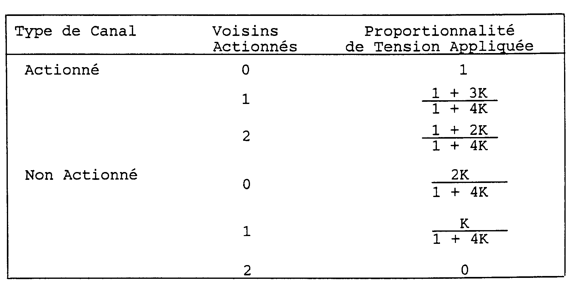
19. Procédé de fonctionnement d'un appareil de dépôt de gouttelettes à réseau à canaux
multiples comprenant une série de canaux parallèles uniformément espacés par des parois
latérales de séparation de canaux, lesdites parois latérales ayant une déformabilité
élastique de paroi, des buses respectives en communication avec lesdits canaux pour
l'éjection de gouttelettes de liquide à partir des canaux, des moyens de fourniture
de liquide de formation de gouttelettes connectés aux canaux pour amener aux canaux
un liquide de formation de gouttelettes ayant une déformabilité élastique de liquide,
et des moyens électriquement actionnables placés par rapport auxdits canaux de manière
à appliquer des impulsions d'énergie au liquide de formation de gouttelettes contenu
dans les canaux afin d'effectuer une éjection de gouttelettes à partir des canaux,
caractérisé en ce qu'il comprend les étapes de sélection d'un groupe de canaux successifs
parmi les canaux de la série et d'application aux canaux dudit groupe, par l'intermédiaire
desdits moyens électriquement actionnables, des impulsions d'énergie d'une première
amplitude pour effectuer, dans un premier demi-cycle de fonctionnement, une éjection
de gouttelettes à partir de canaux alternés parmi les canaux du groupe choisi et,
dans un deuxième demi-cycle de fonctionnement, une éjection de gouttelettes à partir
des autres des canaux du groupe ; et d'application aux canaux, situés de part et d'autre
dudit groupe choisi de canaux, d'impulsions d'énergie d'une deuxième amplitude, lesdites
première et deuxième amplitudes étant fonction d'un rapport de ladite déformabilité
de paroi et de ladite déformabilité de liquide de façon à compenser l'interférence
de pression entre les canaux du groupe choisi, ou entre ledit groupe choisi de canaux
et les autres canaux de la série.
20. Procédé suivant la revendication 19, dans lequel l'étape d'application d'impulsions
d'énergie au liquide dans les canaux comprend l'application de tensions de canal pour
chacun desdits canaux.
21. Procédé suivant la revendication 20, dans lequel chaque tension de canal a un premier
niveau de tension dans ledit premier demi-cycle de fonctionnement et un deuxième niveau
de tension dans ledit deuxième demi-cycle de fonctionnement.
22. Procédé suivant la revendication 21, dans lequel ledit groupe choisi de canaux comprend
un nombre impair de canaux, dans lequel ledit premier niveau de tension pour les canaux
de rang impair du groupe choisi est proportionnel à M et il est de zéro pour les canaux
de rang pair du groupe choisi, dans lequel ledit premier niveau de tension pour les
canaux respectifs situés de part et d'autre dudit groupe de canaux choisi et adjacents
à ce groupe est proportionnel à

et il est proportionnel à

pour les canaux respectifs situés de part et d'autre dudit groupe de canaux choisi et à une distance d'un canal, deux canaux ou plus dudit groupe de canaux, et dans lequel le dit deuxième niveau de tension pour les canaux de rang pair du groupe choisi est proportionnel à M et il est de zéro pour les canaux de rang impair dudit groupe choisi, et dans lequel ledit niveau de tension pour les canaux respectifs situés de part et d'autre dudit groupe de canaux choisi et adjacents à ce groupe est proportionnel à

et il est proportionnel à

pour les canaux respectifs situés de part et d'autre dudit groupe de canaux choisi et à une distance d'un canal, deux canaux et plus dudit groupe de canaux, M étant un facteur de transformation d'échelle dont la valeur est

et K est ledit rapport des déformabilités.
et il est proportionnel à
pour les canaux respectifs situés de part et d'autre dudit groupe de canaux choisi et à une distance d'un canal, deux canaux ou plus dudit groupe de canaux, et dans lequel le dit deuxième niveau de tension pour les canaux de rang pair du groupe choisi est proportionnel à M et il est de zéro pour les canaux de rang impair dudit groupe choisi, et dans lequel ledit niveau de tension pour les canaux respectifs situés de part et d'autre dudit groupe de canaux choisi et adjacents à ce groupe est proportionnel à
et il est proportionnel à
pour les canaux respectifs situés de part et d'autre dudit groupe de canaux choisi et à une distance d'un canal, deux canaux et plus dudit groupe de canaux, M étant un facteur de transformation d'échelle dont la valeur est
et K est ledit rapport des déformabilités.
23. Procédé suivant la revendication 21, dans lequel ledit groupe choisi de canaux comprend
un nombre impair de canaux, dans lequel ledit premier niveau de tension pour les canaux
de rang impair du groupe choisi est proportionnel à M et il est de zéro pour les canaux
de rang pair du groupe choisi,dans lequel ledit premier niveau de tension pour les
canaux respectifs situés de part et d'autre dudit groupe de canaux choisi et adjacents
à ce groupe est proportionnel à
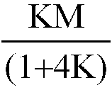
et il est proportionnel à
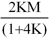
pour les canaux respectifs situés de part et d'autre dudit groupe de canaux choisi et à une distance d'un canal, de deux canaux ou plus dudit groupe de canaux, et dans lequel ledit deuxième niveau de tension pour les canaux respectifs de part et d'autre dudit groupe de canaux choisi et adjacents à ce groupe est proportionnel à

et il est proportionnel à
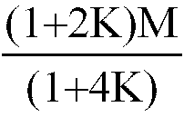
pour les canaux respectifs situés de part et d'autre dudit groupe de canaux choisi et à une distance d'un canal, de deux canaux et plus dudit groupe de canaux, M étant un facteur de transformation d'échelle dont la valeur est

et où K est ledit rapport des déformabilités et KOPT est la valeur optimale de K et est donnée par
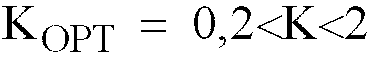
.
et il est proportionnel à
pour les canaux respectifs situés de part et d'autre dudit groupe de canaux choisi et à une distance d'un canal, de deux canaux ou plus dudit groupe de canaux, et dans lequel ledit deuxième niveau de tension pour les canaux respectifs de part et d'autre dudit groupe de canaux choisi et adjacents à ce groupe est proportionnel à
et il est proportionnel à
pour les canaux respectifs situés de part et d'autre dudit groupe de canaux choisi et à une distance d'un canal, de deux canaux et plus dudit groupe de canaux, M étant un facteur de transformation d'échelle dont la valeur est
et où K est ledit rapport des déformabilités et KOPT est la valeur optimale de K et est donnée par
.
24. Procédé suivant la revendication 21, dans lequel ledit groupe choisi de canaux comprend
un nombre pair de canaux, dans lequel ledit premier niveau de tension pour les canaux
de rang pair du groupe choisi est proportionnel à M et il est de zéro pour les canaux
de rang impair du groupe choisi, dans lequel ledit premier niveau de tension pour
le canal adjacent audit groupe de canaux sur le côté du premier canal dudit groupe
est proportionnel à
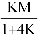
et il est proportionnel à

pour le canal adjacent audit groupe de canaux sur le côté de son dernier canal, il est proportionnel à
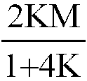
pour chacun des canaux espacés respectivement d'un canal, de deux canaux ou plus par rapport au premier canal dudit groupe de canaux et il est proportionnel à

pour chacun desdits canaux espacés d'un canal, de deux canaux ou plus par rapport au dernier canal dudit groupe de canaux, et dans lequel ledit deuxième niveau de tension pour les canaux de rang impair du groupe choisi est proportionnel à M et il est de zéro pour les canaux de rang pair dudit groupe de canaux choisi, et dans lequel ledit deuxième niveau de tension pour le canal adjacent audit groupe de canaux sur le côté de son premier canal est proportionnel à
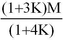
il est proportionnel à

pour le canal adjacent audit groupe de canaux sur le côté de son dernier canal, il est proportionnel à

pour chacun des canaux espacés respectivement par un canal, deux canaux ou plus dudit dernier canal dudit groupe, et il est proportionnel à

pour chacun des canaux espacés respectivement par un canal, deux canaux ou plus du dit premier canal dudit groupe de canaux, M étant un facteur de transformation d'échelle dont la valeur est
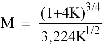
et K est ledit rapport des déformabilités.
et il est proportionnel à
pour le canal adjacent audit groupe de canaux sur le côté de son dernier canal, il est proportionnel à
pour chacun des canaux espacés respectivement d'un canal, de deux canaux ou plus par rapport au premier canal dudit groupe de canaux et il est proportionnel à
pour chacun desdits canaux espacés d'un canal, de deux canaux ou plus par rapport au dernier canal dudit groupe de canaux, et dans lequel ledit deuxième niveau de tension pour les canaux de rang impair du groupe choisi est proportionnel à M et il est de zéro pour les canaux de rang pair dudit groupe de canaux choisi, et dans lequel ledit deuxième niveau de tension pour le canal adjacent audit groupe de canaux sur le côté de son premier canal est proportionnel à
il est proportionnel à
pour le canal adjacent audit groupe de canaux sur le côté de son dernier canal, il est proportionnel à
pour chacun des canaux espacés respectivement par un canal, deux canaux ou plus dudit dernier canal dudit groupe, et il est proportionnel à
pour chacun des canaux espacés respectivement par un canal, deux canaux ou plus du dit premier canal dudit groupe de canaux, M étant un facteur de transformation d'échelle dont la valeur est
et K est ledit rapport des déformabilités.
25. Procédé suivant la revendication 21, dans lequel ledit groupe choisi de canaux comprend
un nombre pair de canaux, dans lequel ledit premier niveau de tension pour les canaux
de rang pair du groupe choisi est proportionnel à M et il est de zéro pour les canaux
de rang impair du groupe choisi, dans lequel ledit premier niveau de tension pour
le canal adjacent audit groupe de canaux sur le côté du premier canal du dit groupe
est proportionnel à
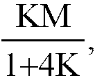
il est proportionnel à

pour le canal adjacent audit groupe de canaux sur le côté de son dernier canal, il est proportionnel à

pour chacun des canaux espacés respectivement par un canal, deux canaux ou plus du premier canal dudit groupe de canaux et il est proportionnel à

pour chacun desdits canaux espacés par un canal, deux canaux ou plus du dernier canal dudit groupe de canaux, et dans lequel ledit deuxième niveau de tension pour les canaux de rang impair du groupe choisi est proportionnel à M et il est de zéro pour les canaux de rang pair dudit groupe de canaux choisi, et dans lequel ledit deuxième niveau de tension pour le canal adjacent audit groupe de canaux sur le côté de son premier canal est proportionnel à
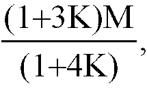
il est proportionnel à

pour le canal adjacent audit groupe de canaux sur le côté de son dernier canal, il est proportionnel à

pour chacun des canaux espacés respectivement par un canal, deux canaux ou plus dudit dernier canal dudit groupe et il est proportionnel à

pour chacun des canaux espacés respectivement par un canal, deux canaux ou plus dudit premier canal dudit groupe de canaux, M étant un facteur de transformation d'échelle dont la valeur est

et où K est ledit rapport de déformabilité et KOPT est la valeur optimale de K et est donnée par

.
il est proportionnel à
pour le canal adjacent audit groupe de canaux sur le côté de son dernier canal, il est proportionnel à
pour chacun des canaux espacés respectivement par un canal, deux canaux ou plus du premier canal dudit groupe de canaux et il est proportionnel à
pour chacun desdits canaux espacés par un canal, deux canaux ou plus du dernier canal dudit groupe de canaux, et dans lequel ledit deuxième niveau de tension pour les canaux de rang impair du groupe choisi est proportionnel à M et il est de zéro pour les canaux de rang pair dudit groupe de canaux choisi, et dans lequel ledit deuxième niveau de tension pour le canal adjacent audit groupe de canaux sur le côté de son premier canal est proportionnel à
il est proportionnel à
pour le canal adjacent audit groupe de canaux sur le côté de son dernier canal, il est proportionnel à
pour chacun des canaux espacés respectivement par un canal, deux canaux ou plus dudit dernier canal dudit groupe et il est proportionnel à
pour chacun des canaux espacés respectivement par un canal, deux canaux ou plus dudit premier canal dudit groupe de canaux, M étant un facteur de transformation d'échelle dont la valeur est
et où K est ledit rapport de déformabilité et KOPT est la valeur optimale de K et est donnée par
.